Adc Campus Rs Remote Users Manual HiGain H2TU R 402 List 4E Unit User
Remote to the manual ea06ae36-4314-419e-8821-5d78b4ec5658
2015-02-05
: Adc Adc-Campus-Rs-Remote-Users-Manual-504900 adc-campus-rs-remote-users-manual-504900 adc pdf
Open the PDF directly: View PDF ![]() .
.
Page Count: 46
- Overview
- Front Panel
- Installation
- Viewing System Screens
- Monitoring System Activity and Performance
- Loopback Operation
- Appendix A - Specifications
- Appendix B - Functional Operation
- Appendix C - Compatibility
- Appendix D - Product Support
- Appendix E - Abbreviations
- Certification and Warranty
HiGain
HiGain
USER MANUAL
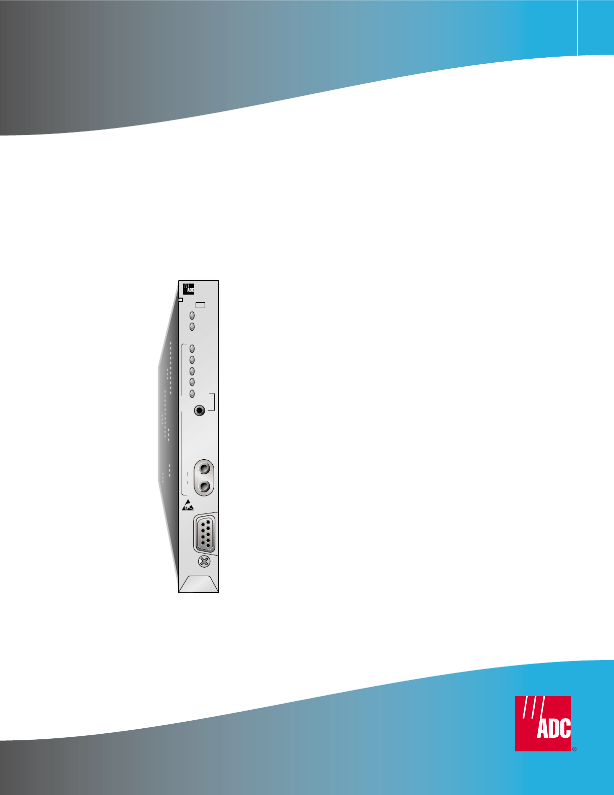
H2TU-R-402 List 4E Remote Unit
Part Number: 150-2450-45
CLEI: VARH1UUC
ALM
L
ESF
SF
LOOP
B8ZS
AMI
LBK
D
S
1
IN
BRG
OUT
RS-232
DCE
H
D
S
L
2
H
2
T
U
*
R
4
0
2
HiGain
4E

152-402-145-02, Issue 2
ii June 16, 2000 H2TU-R-402
Revision History of This Manual
Copyright
January 18, 2002
© 2002 ADC DSL Systems, Inc. All rights reserved.
Trademark Information
ADC is a registered trademark of ADC Telecommunications, Inc. HiGain is a registered trademark of ADC DSL Systems, Inc.
No right, license, or interest to such trademarks is granted hereunder, and you agree that no such right, license, or interest
shall be asserted by you with respect to such trademark. Other product names mentioned in this practice are used for
identification purposes only and may be trademarks or registered trademarks of their respective companies.
Disclaimer of Liability
Information contained in this document is company private to ADC DSL Systems, Inc., and shall not be modified, used, copied,
reproduced or disclosed in whole or in part without the written consent of ADC.
Contents herein are current as of the date of publication. ADC reserves the right to change the contents without prior notice.
In no event shall ADC be liable for any damages resulting from loss of data, loss of use, or loss of profits, and ADC further
disclaims any and all liability for indirect, incidental, special, consequential or other similar damages. This disclaimer of
liability applies to all products, publications and services during and after the warranty period.
Revision Release Date Revisions Made
01 June 16, 2000 Initial release
02 January 18, 2002 ADC branding

152-402-145-02, Issue 2 Using This Manual
H2TU-R-402 June 16, 2000 iii
USING THIS MANUAL
The following conventions are used in this manual:
•Monospace type indicates screen text.
•Keys you press are indicated by small icons such as or . Key combinations to be pressed
simultaneously are indicated with a plus sign as follows: + .
•Items you select are in bold.
•Three types of messages, identified by icons, appear in text.
For a list of abbreviations used in this document, refer to “Appendix E - Abbreviations” on page 37.
INSPECTING SHIPMENT
Upon receipt of the equipment:
•Unpack each container and inspect the contents for signs of damage. If the equipment has been damaged in
transit, immediately report the extent of damage to the transportation company and to ADC DSL Systems,
Inc. Order replacement equipment, if necessary.
•Check the packing list to ensure complete and accurate shipment of each listed item. If the shipment is short
or irregular, contact ADC DSL Systems, Inc. as described in “Appendix D - Product Support” on page 36. If
you must store the equipment for a prolonged period, store the equipment in its original container.
Notes contain information about special circumstances.
Cautions indicate the possibility of personal injury or equipment damage.
The Electrostatic Discharge (ESD) symbol indicates that a device or assembly is susceptible to
damage from electrostatic discharge.
YENTER
CTRL ESC

Table of Contents 152-402-145-02, Issue 2
iv June 16, 2000 H2TU-R-402
TABLE OF CONTENTS
Overview ____________________________________________________________________________ 1
Features.............................................................................................................................................. 1
Compatibility..................................................................................................................................... 2
Applications....................................................................................................................................... 2
Front Panel __________________________________________________________________________ 3
Installation___________________________________________________________________________ 5
Verification........................................................................................................................................ 6
Verification without an Upstream Device .......................................................................... 6
Verification with an Upstream Device................................................................................ 6
Viewing System Screens________________________________________________________________ 7
Connecting to a Maintenance Terminal ............................................................................................7
Logon Screen..................................................................................................................................... 7
Monitoring System Activity and Performance ____________________________________________ 10
Using the Monitor Screen to View System Activity....................................................................... 10
Using the Performance Screens to View Performance Data........................................................... 12
Performance History at the DS1 Interface ........................................................................ 12
Performance History at the HDSL2 Interface................................................................... 17
Using the Performance Screens to View Alarm Data ..................................................................... 19
Alarm History at the DS1 Interface .................................................................................. 19
Alarm History at the HDSL2 Interface............................................................................. 21
Using the Event Log to Track System Events................................................................................. 22
Loopback Operation__________________________________________________________________ 24
Generic Loopback Commands.......................................................................................... 24
Special Loopback Commands........................................................................................... 26
Loopback Test Procedures .............................................................................................................. 26
GNLB Test Procedures ..................................................................................................... 26
A2LB Test Procedures...................................................................................................... 28
A3LB and A4LB Test Procedures .................................................................................... 30
Appendix A - Specifications____________________________________________________________ 31
Loop Attenuation............................................................................................................................. 32
H2TU-R-402 List 4E Card Connector ............................................................................................ 32
Craft Port ......................................................................................................................................... 33
Appendix B - Functional Operation _____________________________________________________ 34
Timing ............................................................................................................................................. 34
Appendix C - Compatibility____________________________________________________________ 35
Appendix D - Product Support _________________________________________________________ 36
Appendix E - Abbreviations____________________________________________________________ 37
Certification and Warranty _____________________________________________ Inside Back Cover

152-402-145-02, Issue 2 List of Tables
H2TU-R-402 June 16, 2000 v
LIST OF TABLES
1. Front-Panel Description.................................................................................................................................4
2. Logon Screen Menus....................................................................................................................................8
3. Navigational Keys for the HiGain HDSL2 Maintenance Terminal Screens.................................................9
4. Monitor Screen Descriptions.......................................................................................................................11
5. Error Acronyms Used on the DS1 Performance History Screens...............................................................16
6. Error Acronyms Used on the HDSL2 Performance History Screens..........................................................19
7. H2TU-R DS1 Alarm Descriptions ..............................................................................................................20
8. H2TU-R HDSL2 Alarm Descriptions.........................................................................................................22
9. Event Log Messages....................................................................................................................................23
10. Summary of HiGain HDSL2 Loopback Codes and Activation Methods ...................................................25
11. Addressable Repeater Loopback Commands (A2LB) ................................................................................28
12. Addressable Repeater Loopback Commands (A3LB and A4LB)...............................................................30
13. HDSL2 Cable Attenuation Chart.................................................................................................................32

List of Figures 152-402-145-02, Issue 2
vi June 16, 2000 H2TU-R-402
LIST OF FIGURES
1. H2TU-R-402 List 4E Front Panel................................................................................................................. 3
2. Installing the H2TU-R-402 List 4E .............................................................................................................. 5
3. Logon Screen ................................................................................................................................................ 8
4. Monitor Screen - Active Loopback with Alarms........................................................................................ 10
5. H2TU-R DS1 31-day Performance History................................................................................................ 12
6. H2TU-C DS1 31-day Performance History................................................................................................ 13
7. H2TU-R DS1 48-hour Performance History.............................................................................................. 13
8. H2TU-C DS1 48-hour Performance History.............................................................................................. 14
9. H2TU-R DS1 25-hour Performance History.............................................................................................. 14
10. H2TU-C DS1 25-hour Performance History.............................................................................................. 15
11. H2TU-R DS1 Current Statistics.................................................................................................................. 15
12. H2TU-R HDSL2 31-day Performance History .......................................................................................... 17
13. H2TU-R HDSL2 48-hour Performance History......................................................................................... 17
14. H2TU-R HDSL2 25-hour Performance History......................................................................................... 18
15. H2TU-R HDSL2 Current Statistics ............................................................................................................ 18
16. H2TU-R DS1 Alarm History Screen .......................................................................................................... 19
17. H2TU-C DS1 Alarm History Screen .......................................................................................................... 20
18. H2TU-R HDSL2 Alarm History Screen..................................................................................................... 21
19. H2TU-C HDSL2 Alarm History Screen..................................................................................................... 21
20. System Event Log....................................................................................................................................... 22
21. Loopback Summary.................................................................................................................................... 24
22. Loopback Modes......................................................................................................................................... 27
23. H2TU-R-402 List 4E Card-Edge Connector .............................................................................................. 32
24. RS-232 Craft Port Pinouts .......................................................................................................................... 33
25. H2TU-R-402 List 4E Block Diagram......................................................................................................... 34

152-402-145-02, Issue 2 Overview
H2TU-R-402 June 16, 2000 1
OVERVIEW
The HiGain® HDSL2 product family from ADC® is the industry’s first practical implementation of High-bit-rate
Digital Subscriber Line 2 (HDSL2). ADC products are fully compliant with the HDSL2 standard. Providing
full-rate T1 access using just a single copper pair, HDSL2 is a cost-effective solution that offers an open
architecture. The open architecture inherent in HDSL2 guarantees interoperability, allowing simple and economic
accommodation of network growth. HiGain HDSL2 uses the industry’s first HDSL2 chipset (ANSI T1/E1.4
compliant) developed by ADC.
HiGain HDSL2 products provide 1.552 Mbps transmission on one unconditioned copper pair over the full Carrier
Service Area (CSA) range. The CSA includes loops up to 12,000 feet of 24 American Wire Gauge (AWG) wire
or 9,000 feet of 26 AWG wire, including bridged taps.
FEATURES
The H2TU-R-402 List 4E remote unit is the customer side of a T1 transmission system.
•HDSL2 transmission features
–Lightning and power cross-protection on HDSL2 interfaces
–Full-duplex HDSL2 transmission on one pair at 1.552 Mbps
–Ultra-low wander (Stratum 1 compliant)
•Front-panel features
–HDSL and DS1 status LEDs
–Dual loopback control button
–DS1 access bridging jacks
–RS-232 craft port for connection to a maintenance terminal
•HiGain HDSL2 maintenance screens for inventory, provisioning, and troubleshooting
–High-performance, non-volatile performance monitoring
–Non-volatile alarm histories
–Performance Report Messaging (PRM) support for Supplemental PRM (SPRM) and Network PRM
(NPRM)
•System configuration options
–Selectable DS1 pre-equalizer
–Bipolar Violation Transparency (BPVT)
–Bit Error Rate (BER) alarm
–Remote provisioning
–Selectable loopback activation codes
•Digital Data Service (DDS) latching loopback
•Payload (PL) and HiGain (HG) loopback source identification
•Line or local power with sealing current option
•Metallic loopback self tests

Overview 152-402-145-02, Issue 2
2 June 16, 2000 H2TU-R-402
COMPATIBILITY
The H2TU-R-402 is designed to mount in any 400 or 200 mechanics shelf. For a list of compatible shelves see
“Appendix C - Compatibility” on page 35.
APPLICATIONS
HiGain HDSL2 systems provide a cost-effective, easy-to-deploy method for delivering T1 High Capacity Digital
Service (HCDS) over a single copper pair. HiGain HDSL2 systems support a multitude of network connections
and system models.
•The service is deployed over one unconditioned, non-loaded copper pair.
•Conventional, inline T1 repeaters are no longer required.
•Cable pair conditioning, pair separation, and bridged tap removal are not required.
In general, HiGain HDSL2 systems:
•Operate effectively in the same cable binder group with other HDSL2 lines, HDSL, T1, ADSL, SDSL, POTS,
DDS, and other transmission schemes.
•Can be used with customers requiring DS1 service on a temporary or permanent basis.
•Provide a means of quickly deploying service in advance of fiber-optic transmission systems.
DS1 is used throughout this document to refer to either the remote unit’s DS1 interface or the
line unit’s DSX-1 interface.
152-402-145-02, Issue 2 Front Panel
H2TU-R-402 June 16, 2000 3
FRONT PANEL
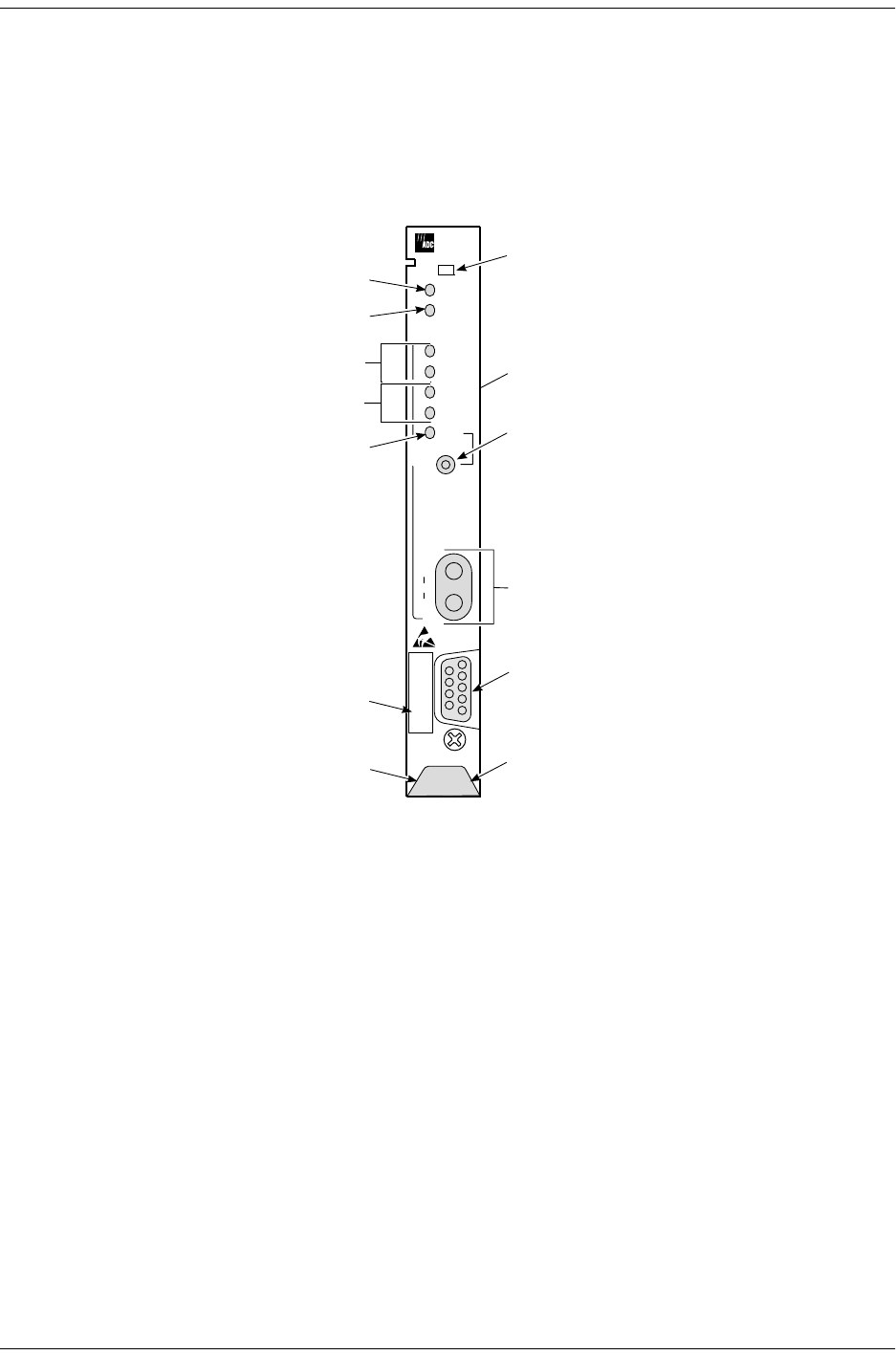
Figure 1 shows the H2TU-R-402 List 4E front panel. Table 1 on page 4 describes the front-panel components. For
pinout diagrams of the H2TU-R card-edge connector and craft port, refer to “Appendix A - Specifications” on
page 31.
Figure 1. H2TU-R-402 List 4E Front Panel
ALM
L
ESF
SF
LOOP
B8ZS
AMI
LBK
H
D
S
L
2
H
2
T
U
*
R
4
0
2
D
S
1
IN
BRG
OUT
RS-232
DCE
HiGain
Alarm LED
Loopback LED
CLEI/ECI bar code label
Loop LED
DS1 framing LEDs
DS1 line code LEDs
Craft port (RS-232)
Loopback pushbutton
Extraction handle
DS1 bridging (BRG) jacks
Configuration number label
(inside handle)
4E
List number
Sealing current (SCURR) switch
(at rear of circuit board)

Front Panel 152-402-145-02, Issue 2
4 June 16, 2000 H2TU-R-402
Table 1. Front-Panel Description
Front-panel Feature Function
List number Identifies the list number of the H2TU-R-402.
Alarm (ALM) LED Shows alarm states for remote and local Loss of Signal (LOS).
Steady red Indicates a Loss of Signal (LOS) condition at the T1 input of the H2TU-R-402.
Blinking Indicates an LOS condition at the T1 input of the H2TU-C line unit.
Loop LED Displays HDSL2 Loop condition.
Steady green Indicates HDSL2 loop is in sync.
Blinking once
per second Indicates the HDSL2 loop is trying to acquire sync.
Blinking 4 times
per second Indicates a margin alarm condition on the HDSL2 loop.
Blinking 10 times
per second Indicates a Cyclic Redundancy Check (CRC) error on the HDSL2 loop.
OFF Indicates no activity on the HDSL2 loop.
DS1 Framing LEDs (ESF and SF) Indicates framing patterns. If DS1 signals are not detected, the ESF and SF LEDs will not light.
ESF LED = Steady green Indicates Extended Super Frame (ESF). The LED blinks once per second when a frame error
occurs.
SF LED = Steady green Indicates Super Frame (SF). The LED blinks once per second when a frame error occurs.
OFF Indicates unframed or no signal.
DS1 Line Code LEDs (B8ZS and
AMI) Indicates DS1 code options. If DS1 signals are not detected, the ESF, SF, B8ZS, and AMI LEDs
will not light.
B8ZS LED =Steady green Indicates that the DS1 line code option is set to Bipolar with 8-Zero Substitution (B8ZS). The LED
blinks once per second when a string of excessive zeros is detected.
AMI LED = Steady green Indicates that the user DS1 line code option is set to Alternate Mark Inversion (AMI). This LED
blinks once per second when a Bipolar Violation (BPV) is detected.
Loopback (LPBK) LED Shows loopback states to and from the network and to and from the Customer Interface (CI).
Steady yellow Indicates Network Remote (NREM) loopback, SmartJack (SMJK) loopback, or Transmit Loss of
Signal (TLOS) loopback.
Blinking once
per second Indicates Customer Local Loopback (CLOC) loopback state.
Blinking 4 times per second Indicates the H2TU-R is in an Armed state.
Loopback pushbutton Activates or deactivates a dual loopback (NREM and CLOC) at the H2TU-R when the button is
depressed for more than five (5) seconds.
Sealing current (SCURR) switch Enables sealing current option when H2TU-R is locally powered.
DS1 bridging (BRG) jacks Provides non-intrusive bridging jack access to (OUT) and from (IN) the HDSL2 span at the DS1
interface. Allows the DS1 payload to be monitored.
Craft port (RS-232) Provides bidirectional communication between the unit and an external terminal to allow
configuration and performance monitoring through the maintenance terminal screens.
CLEI and ECI bar code label Provides the human-readable Common Language Equipment Identifier (CLEI) code number and
the Equipment Catalog Item (ECI) bar code number.
Configuration number The configuration number identifies the version of the product. New configuration numbers
usually accompany changes in the last two characters of the CLEI code.
The configuration number is found on a small label attached to the PC board. It can also be found
as the last two numbers (following the x) of the 13-character part number label affixed to the PC
board. For example: 150-1234-01-x01.
Extraction handle Used to remove the H2TU-R-402 from its card slot.
152-402-145-02, Issue 2 Installation
H2TU-R-402 June 16, 2000 5
INSTALLATION
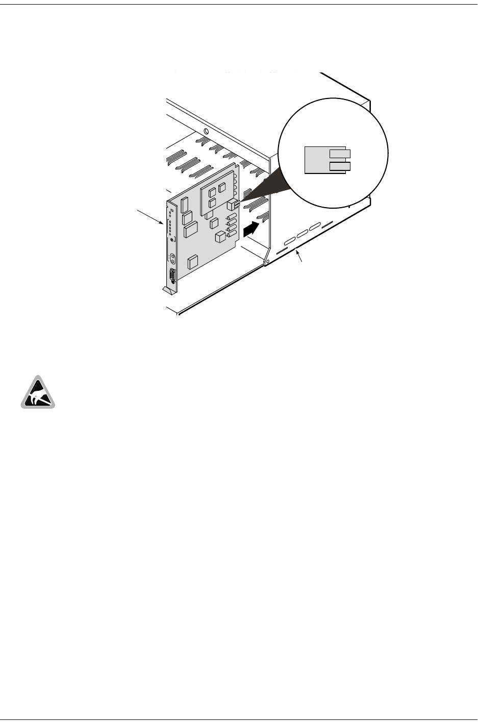
Figure 2. Installing the H2TU-R-402 List 4E
1Check the setting of the SCURR switch. The default setting is disabled (up position). If the H2TU-R is locally
powered, and your application requires sealing current, place the SCURR switch in the down position.
2Align the H2TU-R with the enclosure slot guides and slide the unit in. Push the unit back until it touches the
backplane card-edge connector.
3Place your thumbs on the front panel and push the H2TU-R into the card-edge connector.
Wear an antistatic wrist strap when installing the H2TU-R. Avoid touching components on the
circuit board.
H2TU-R-402
Remote enclosure
SOLITAIRE
ALM
L
LOOP
ESF
SF
B8ZS
AMI
LBK
H
D
S
L
2
D
S
1
IN
BRG
OUT
RS-232
DCE
SCURR
SCURR SWITCH

Installation 152-402-145-02, Issue 2
6 June 16, 2000 H2TU-R-402
VERIFICATION
Verification without an Upstream Device
Verify that the H2TU-R powers up. The following should occur:
•The front-panel ALM LED is a steady red.
•The LOOP LED is flashing green.
•If receiving a DS1 signal, one of the DS1 framing LEDs (ESF or SF) and one of the DS1 line code LEDs
(B8ZS or AMI) is a steady green.
Verification with an Upstream Device
1Verify that the H2TU-R powers up.
•The front-panel ALM LED is a steady red.
•The LOOP LED is flashing green.
•If receiving a DS1 signal, one of the DS1 framing LEDs (ESF or SF) and one of the DS1 line code LEDs
(B8ZS or AMI) is a steady green.
2Verify that the H2TU-R attempts to communicate with an upstream device (LOOP LED is flashing green).
One of the following occurs:
•If an upstream device is successfully identified and the HDSL2 loop synchronizes, the LOOP LED lights
a steady green.
•If upstream devices are not successfully identified, the H2TU-R continues to attempt communication
(LOOP LED flashes green) until an upstream device is detected.

152-402-145-02, Issue 2 Viewing System Screens
H2TU-R-402 June 16, 2000 7
VIEWING SYSTEM SCREENS
The H2TU-R-402 supports both local and remote logon through a maintenance terminal (ASCII terminal or PC
running terminal emulation software) connected to its front-panel craft port.
From the maintenance terminal you can access menus and screens that are replications of those viewed at the H2TU-C. You
can view system settings and inventory, initiate loopbacks, and monitor performance. If the Remote Provisioning option is
enabled at the H2TU-C, you can configure the circuit.
CONNECTING TO A MAINTENANCE TERMINAL
To connect to a maintenance terminal:
1Connect a standard 9-pin serial cable to the RS-232 craft port (Figure 1 on page 3) on the H2TU-R-402 front
panel.
2Connect the other end of the cable to the serial port on the maintenance terminal.
3Start a terminal emulation program such as ProComm (emulating a VT100 terminal).
4Configure the maintenance terminal to the following communication settings:
•9600 baud
•No parity
•8 data bits
•1 stop bit
•Hardware flow control to OFF
5If necessary, press + to refresh the HiGain HDSL2 logon screen.
LOGON SCREEN
The maintenance terminal screens allow you to monitor, provision, and troubleshoot the HiGain HDSL2 system.
To select a menu from the HiGain HDSL2 logon screen (Figure 3 on page 8), do one of the following:
•Press the first letter of the menu.
•Use the arrow keys to select the menu, and then press .
Table 2 on page 8 describes the Logon screen menus. Table 3 on page 9 summarizes the navigational keys. They
are also listed in the onscreen Help menu.
Initial provisioning of the HiGain HDSL2 system is performed at the H2TU-C line unit. For more
information about the HiGain HDSL2 screens, provisioning, and troubleshooting, download the
appropriate H2TU-C line unit user manual from the ADC website at www.adc.com. To order a
hard copy, please contact your sales representative.
CTRL R
← → ENTER
Viewing System Screens 152-402-145-02, Issue 2
8 June 16, 2000 H2TU-R-402
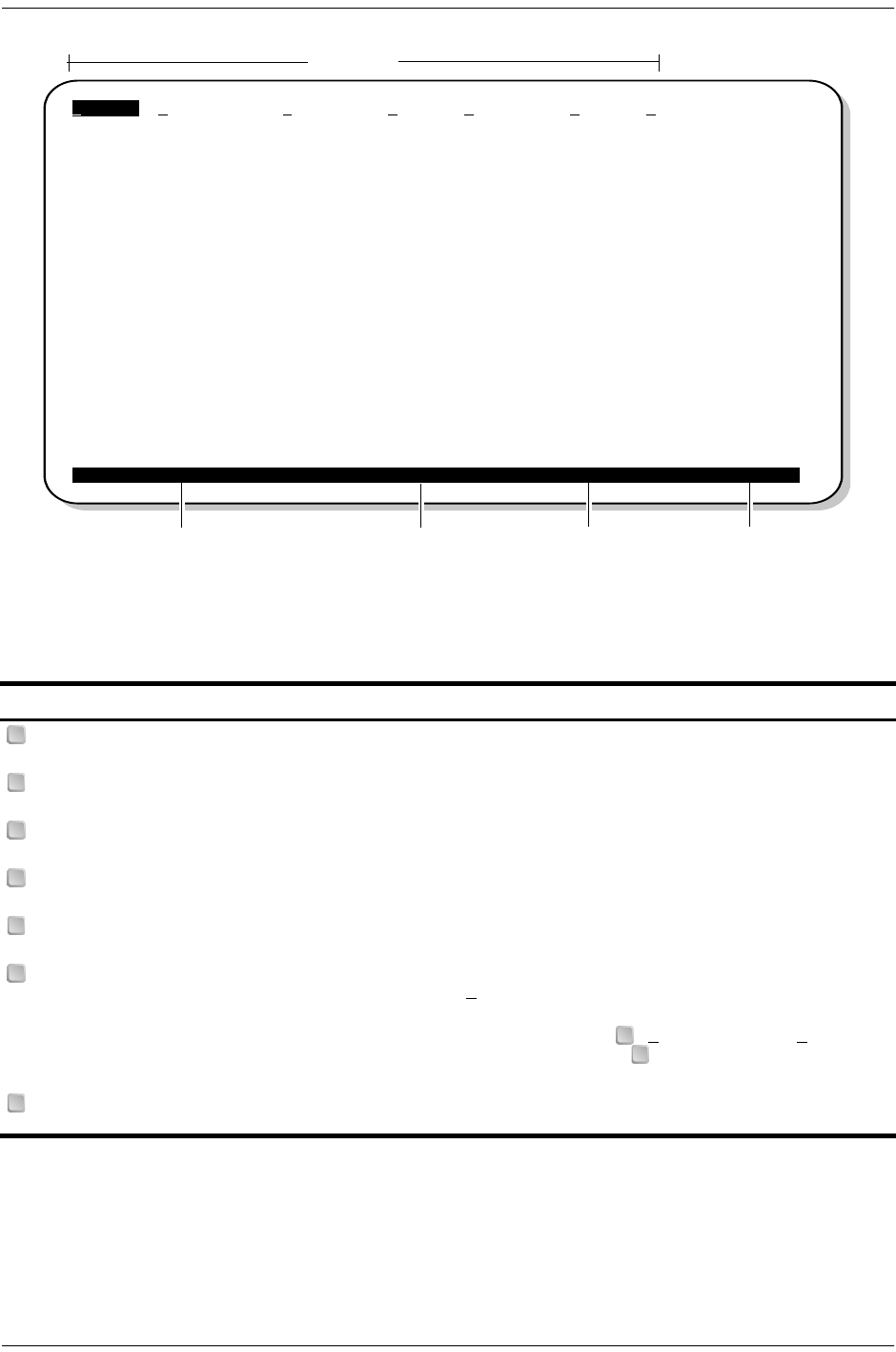
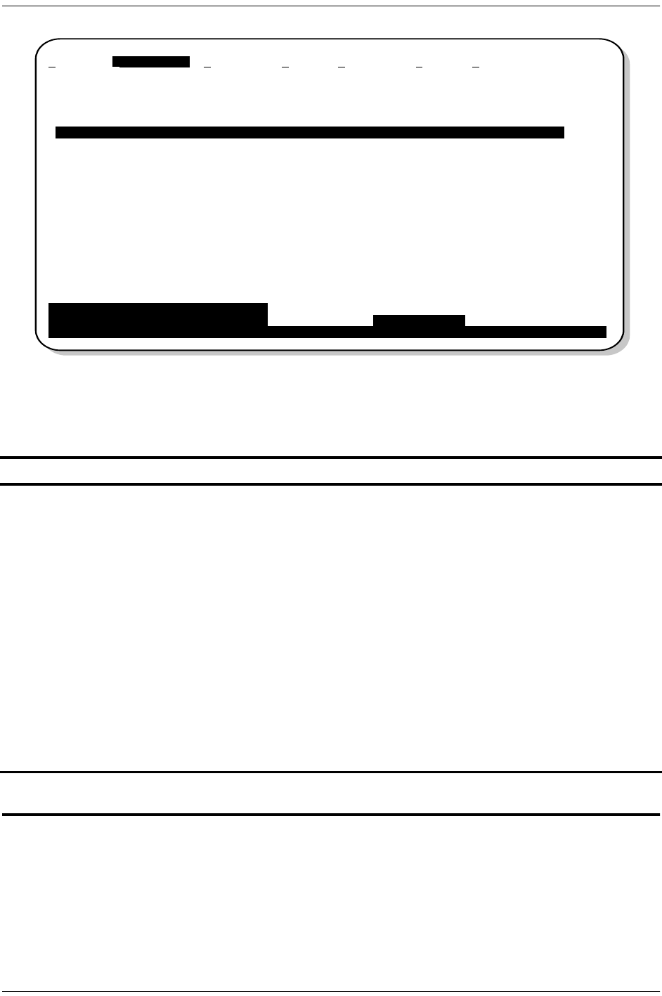
Figure 3. Logon Screen
Table 2. Logon Screen Menus
Press this key: To access this menu: Menu Functions
Monitor Monitors loopbacks and alarms, and provides a graphical representation
of circuit activity, including ES, UAS, SES, and line code.
Performance Provides performance and alarm histories for current, 25-hour, 48-hour,
or 31-day periods for either the DS1 or HDSL2 interface.
Event Log Identifies the 100 most recent system events and reports the date and
time of occurrence.
Config Provides standard configuration options, ADC options, date and time
setting, and a reset option (factory settings).
Inventory Provides product information about the various devices that are in the
system and lists circuit and device identifications.
Rlogon / Rlogout Remote logon can be performed from the H2TU-R or H2TU-C. The screen
displays “Rlogout” when the H2TU-R or H2TU-C is remotely logged on to
the other unit at the end of the circuit.
To logoff the remote unit, press . “Rlogout” changes to “Rlogon”. The
unit is now locally logged on until is pressed again to re-initiate the
remote logon.
Help Provides a glossary of terms used in the HiGain HDSL2 maintenance
screens, a list of navigational keys, and ADC contact information.
Circuit ID Number Date and Time Logon Device System Status
Menu bar
Monitor Performance Event Log Config Inventory Rlogon Help
+--------------------------------------------+
||
| PairGain Technologies Inc. |
| HiGain Solitaire HDSL2 |
||
| Voice: 800.638.0031 |
| Fax : 714.832.9924 |
| Web : www.pairgain.com |
+--------------------------------------------+
ID: xxxx--xxxx--xxxx--xxxx 04/15/00 12:30:01 H2TU-R System: OK
M
P
E
C
I
R
RR
H

152-402-145-02, Issue 2 Viewing System Screens
H2TU-R-402 June 16, 2000 9
Table 3. Navigational Keys for the HiGain HDSL2 Maintenance Terminal Screens
Key (a)
(a) Legacy management units require use of control keys instead of arrow keys.
Function
Cycle through selections.
Activate the current setting or choice, or display a menu.
or (VT100) Return to the parent menu.
or + Select the submenu or item above the current one, or return to the previous menu.
or + Select the submenu or item below the current one.
or + Select the menu or item to the right of the current one.
or + Select the menu or item to the left of the current one, or return to the previous menu.
+ Refresh the screen.
SPACEBAR
ENTER
ESC F11
↑CTRL E
↓CTRL X
→CTRL D
←CTRL S
CTRL R
Monitoring System Activity and Performance 152-402-145-02, Issue 2
10 June 16, 2000 H2TU-R-402
MONITORING SYSTEM ACTIVITY AND
PERFORMANCE
The HiGain HDSL2 system provides the following maintenance screens for monitoring system activity and
assessing performance.
•The Monitor screens provide a graphical representation of circuit activity and allow initiation of loopbacks.
•The Performance screens provide current, 25-hour, 48-hour, and 31-day performance histories and a
continuous alarm history.
•The Event Log provides a description of the 100 most recent events.
•The Sectionalized Event Log screen displays events for all four legs of the H2TU-R DS1 interface.
USING THE MONITOR SCREEN TO VIEW SYSTEM ACTIVITY
1Press to view the system diagram.
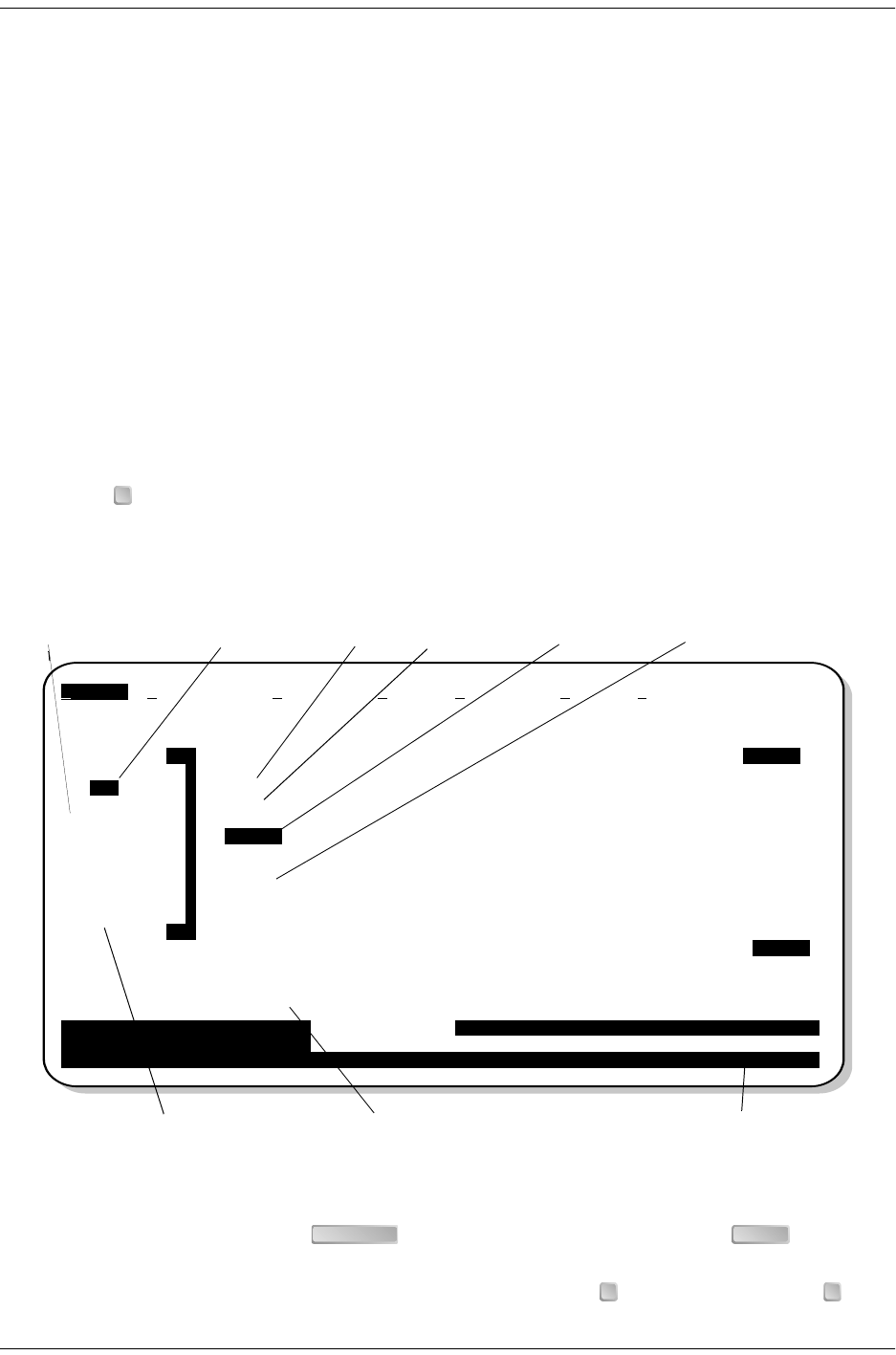
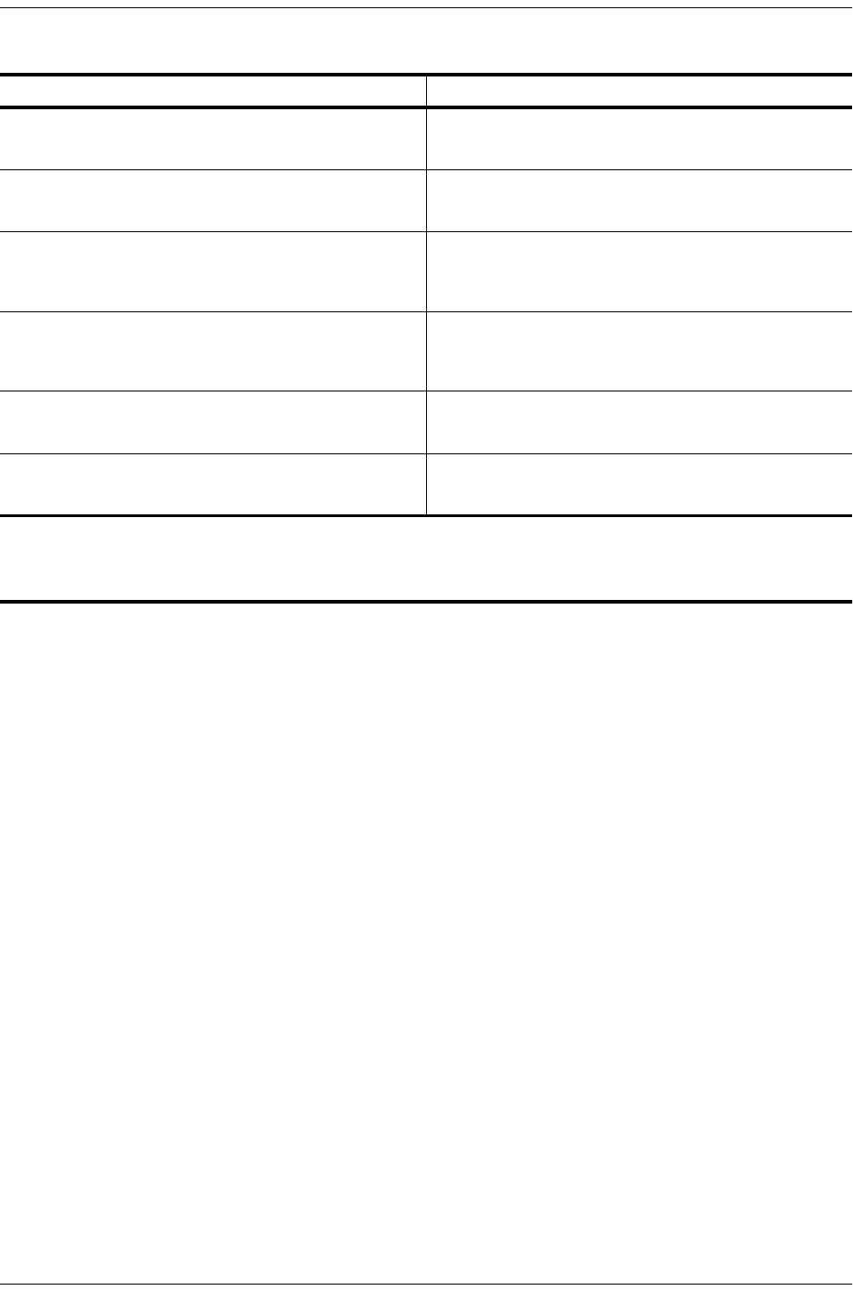
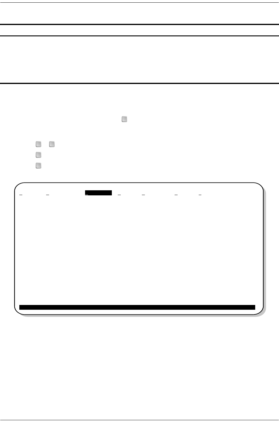
Figure 4 shows an armed circuit with an active loopback and alarms. Terms used on the system diagram are
defined in the onscreen Help menu glossary. Abnormal situations are highlighted on the diagram. See Table 4
on page 11 for screen field descriptions.
Figure 4. Monitor Screen - Active Loopback with Alarms
2To initiate a loopback, press the to cycle though the loopback choices. Press to make your
choice.
3When prompted with the message: Are you sure (Y/N)?, press to initiate the loopback or to
cancel. For more information about loopbacks and troubleshooting, see “Loopback Operation” on page 24.
M
Armed mode Margin Loop attenuation Alarm type HDSL2 Errors
Line code and framing Active loopback System status
DS1 Errors
Monitor Performance Event Log Config Inventory Rlogon Help
ESF +---+ +---+
B8ZS |H2C| |H2R|
------->|-+ |||-AIS ->
|||||
ARM |||M =19 M =18 | |
|||LA=25 LA =25 | |
ES =3 | ||||ES=1
SES=3 | ||=MAL ==========================================| | SES=1
UAS=0 | || | | UAS=0
|||ES =41 ES =1 | | PRM=0
|||SES=41 SES=1 | |
ESF | ||UAS=38 UAS=0 | |
B8ZS | ||||
<-------<-+ |||
|LPF| | |<-RLOS -
+---+ +---+
----------------------------------LOOPBACKS------------------------------------
Active Loopback: NLOC-PL
Press <Space> to select LB New Loopback: NLOC - Loopback H2TU-C towards Network
and <Enter> to activate (LPDN,NLOC,CREM,NREM,CLOC)
ID: xxxx--xxxx--xxxx--xxxx 04/15/00 12:30:01 H2TU-R System: Alarm
SPACEBAR ENTER
Y N

152-402-145-02, Issue 2 Monitoring System Activity and Performance
H2TU-R-402 June 16, 2000 11
4To initiate a loopdown of all active loopbacks, press the to select LPDN, then press or
. When prompted with the message: Are you sure (Y/N)?, press to initiate the loopdown or to
cancel.
Table 4. Monitor Screen Descriptions
Field Description
Active Loopback An active loopback is indicated on the lower third of the Monitor screen. Available loopbacks are
indicated by gray text. See Table 10 on page 25 for a summary of the HiGain HDSL2 loopback
codes and activation methods.
Alarm type Indicates type of alarm.
Armed mode Indicates system is in an armed state for an intelligent repeater loopback command.
Code type Type of DS1 line coding used (B8ZS or AMI).
DS1 ES Count Errored Seconds—The sum of the Errored Seconds-Line (ES-L) and Errored Seconds-Path (ES-P)
counts detected on the DS1 input over a 24-hour period. Errors included are: DS1 Frame errors,
BPV, and ESF CRC errors.
DS1 SES Count Severely Errored Seconds—The sum of the DS1 Severely Errored Seconds-Line (SES-L) and
Severely Errored Seconds-Path (SES-P) counts over the last 24 hours.
DS1 UAS Count Unavailable Errored Seconds—The number of seconds during which the DS1 input signal was
absent over a 24-hour period.
Frame type Type of DS1 framing used on the input stream (SF, ESF or UNFR).
HDSL2 ES Count Errored Seconds—The number of 1-second intervals that contained at least one CRC or LOSW
error. This value is a running total of the last 24 Hours.
HDSL2 SES Count Severely Errored Seconds—The number of 1-second intervals that contain at least 50 CRC errors
or one or more LOSW defects. (An LOSW defect occurs when at least three consecutive HDSL
frames contain one or more frame bit errors.) This value is a running total of the last 24 hours.
HDSL2 UAS Count Unavailable Errored Seconds—The number of seconds the HDSL2 loop is unavailable. This occurs
after 10 contiguous HDSL SES and is retired after 10 contiguous non-SES seconds. This value is
a running total of the last 24 hours.
ID Circuit identification (ID) number.
LA Loop Attenuation—indicates the attenuation of the Overlapped Pulse Amplitude Modulation
Transmission with Interlocking Spectra (OPTIS) pulse from the distant end. The value is related to
the 196 kHz loss of the cable pair. The loop attenuation is a more direct indication of the loop
attenuation to the OPTIS signal than is the 196 kHz loss. The normal HiGain HDSL2 LA operation
range is from 0 to 40 dB.
LPF Line Power Feed—indicates the HDSL2 line power is on.
MMargin—the signal-to-noise ratio at all HDSL2 ports, relative to a 10-7 Bit Error Rate.
MAL Margin Alarm—Indicates the margin on HDSL2 loop has dropped below the threshold (0 to 15dB)
as set by the operator.
PL (or HG) PL displays when the loopback was initiated by a command embedded in the DS1 data path
payload (PL). HG displays when the loopback was initiated from a HiGain (HG) front panel or by a
HiGain maintenance terminal loopback command.
PRM The sum of the Performance Report Messaging-Near End (PRM-NE) and Performance Report
Messaging-Far End (PRM-FE) counts.
System Status The presence or absence of alarms (BER, MARG, LOS, AIS, AIS-CI, RAI, RAI-CI, LA) is indicated
on the lower right corner of all screens.
SPACEBAR ENTER
N Y N

Monitoring System Activity and Performance 152-402-145-02, Issue 2
12 June 16, 2000 H2TU-R-402
USING THE PERFORMANCE SCREENS TO VIEW PERFORMANCE DATA
To access the Performance history screens:
1Press to select the Performance screen.
2Press the to select either interface (H2TU-C DS1, H2TU-R DS1, H2TU-C HDSL2, or H2TU-R
HDSL2), then press .
3Press the to select the type of statistics (Current, Alarm History, 25 Hour History, 48 Hour
History, or 31 Day History), then press .
Performance History at the DS1 Interface
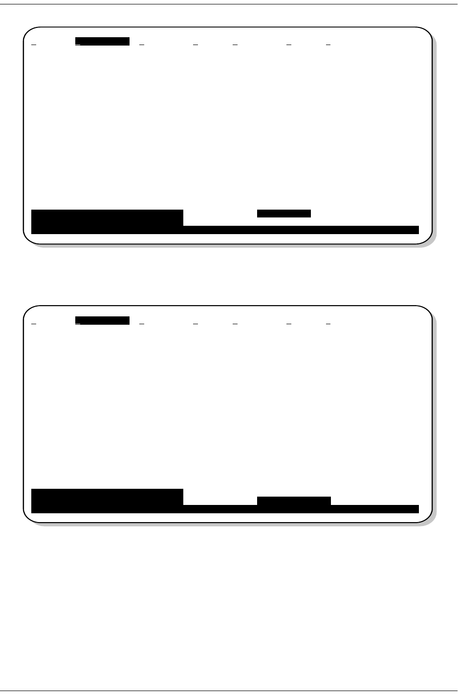
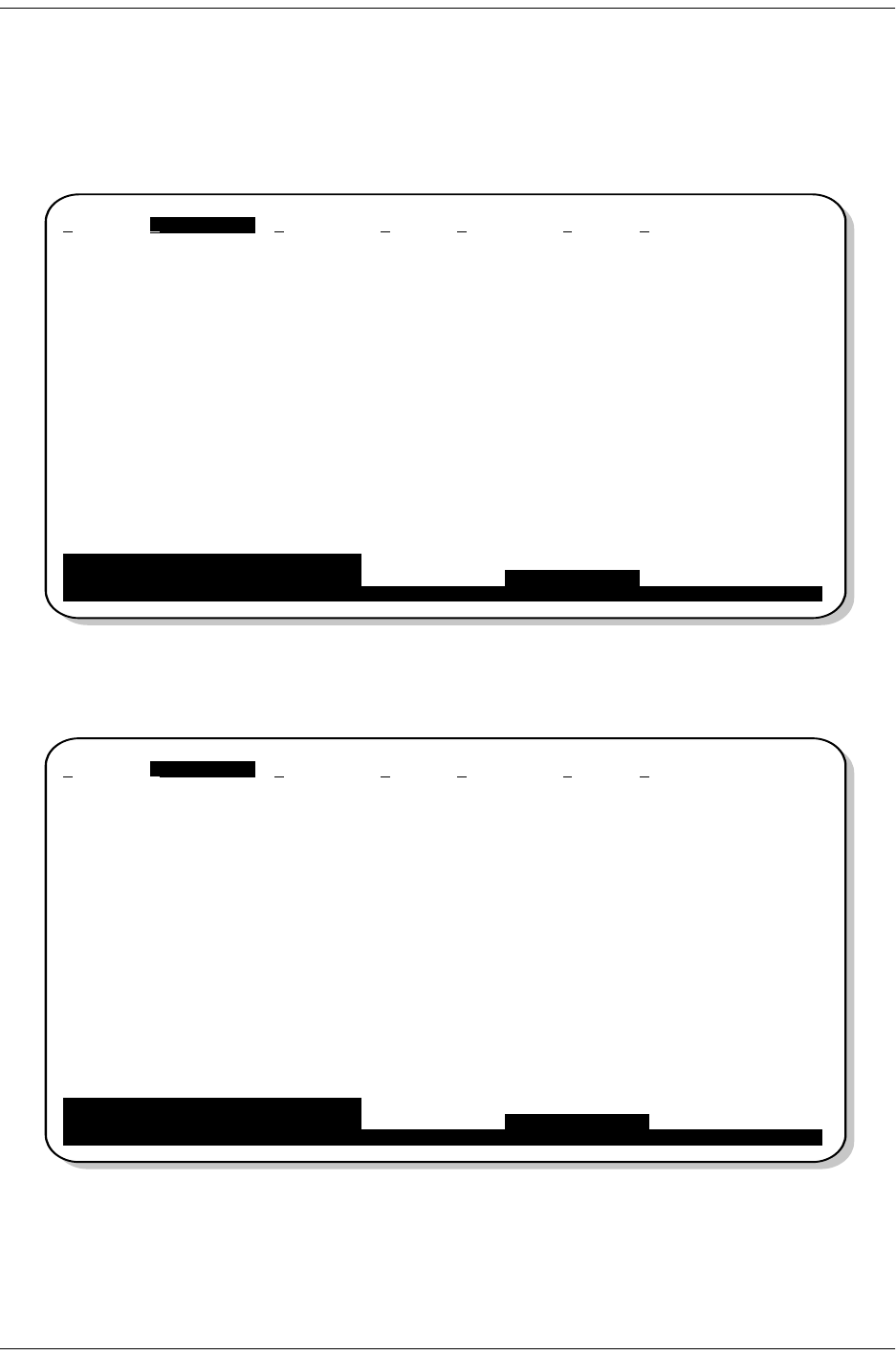
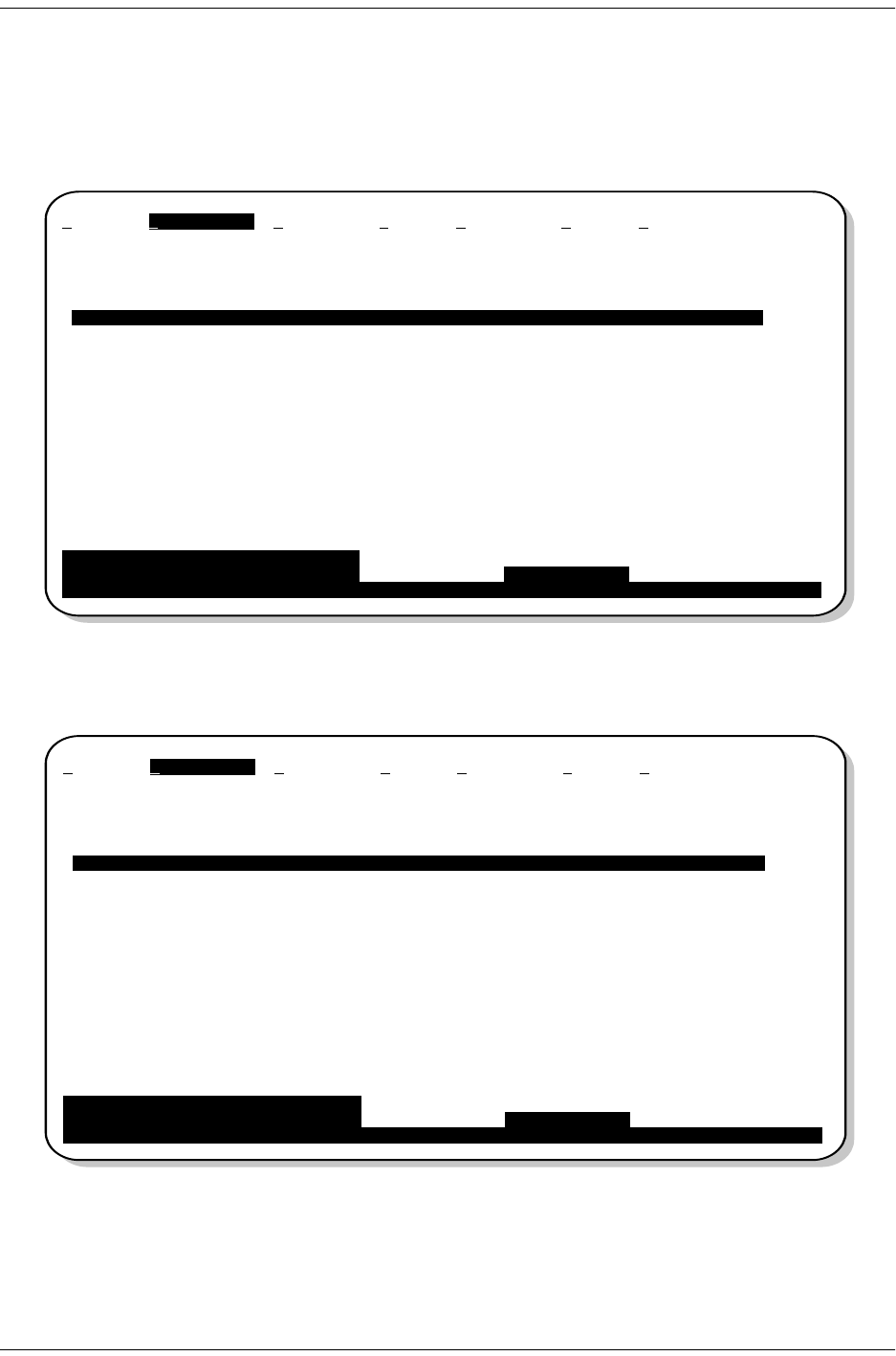
Figure 5 is an example of a 31-Day History screen for the H2TU-R DS1 interface. The DS1 interface provides
31-day, 48-hour, 25-hour, and current statistics screens for the H2TU-R and the H2TU-C. Table 5 on page 16
describes the kinds of errors reported for these screens.
Figure 5. H2TU-R DS1 31-day Performance History
Performance screens for the H2TU-C are shown only when they are different from the H2TU-R
screens.
P
SPACEBAR
ENTER
SPACEBAR
ENTER
Monitor Performance Event Log Config Inventory Rlogon Help
H2TU-R DS-1 31 Day History (Page 1 of 3)
------------------------------------------------------------------------------
Date ES-L SES-L UAS-L CV-L PDVS-L ES-P SES-P UAS-P PRM-NE PRM-FE
04/03 ----------
04/04 ----------
04/05 ----------
04/06 ----------
04/07 ----------
04/08 ----------
04/09 ----------
04/10 ----------
04/11 ----------
04/12 ----------
04/13 ----------
04/141410101210100000
04/15 0002000000
Press: (N)ext Page, (P)revious Page, C(l)ear History
------------------------------------------------------------------------------
Press <Space> to cycle through Interface : H2TU-R DS-1
choices and <Enter> to view Statistics : 31 Day History
ID: xxxx--xxxx--xxxx--xxxx 04/15/00 12:30:01 H2TU-R System: OK
___
152-402-145-02, Issue 2 Monitoring System Activity and Performance
H2TU-R-402 June 16, 2000 13
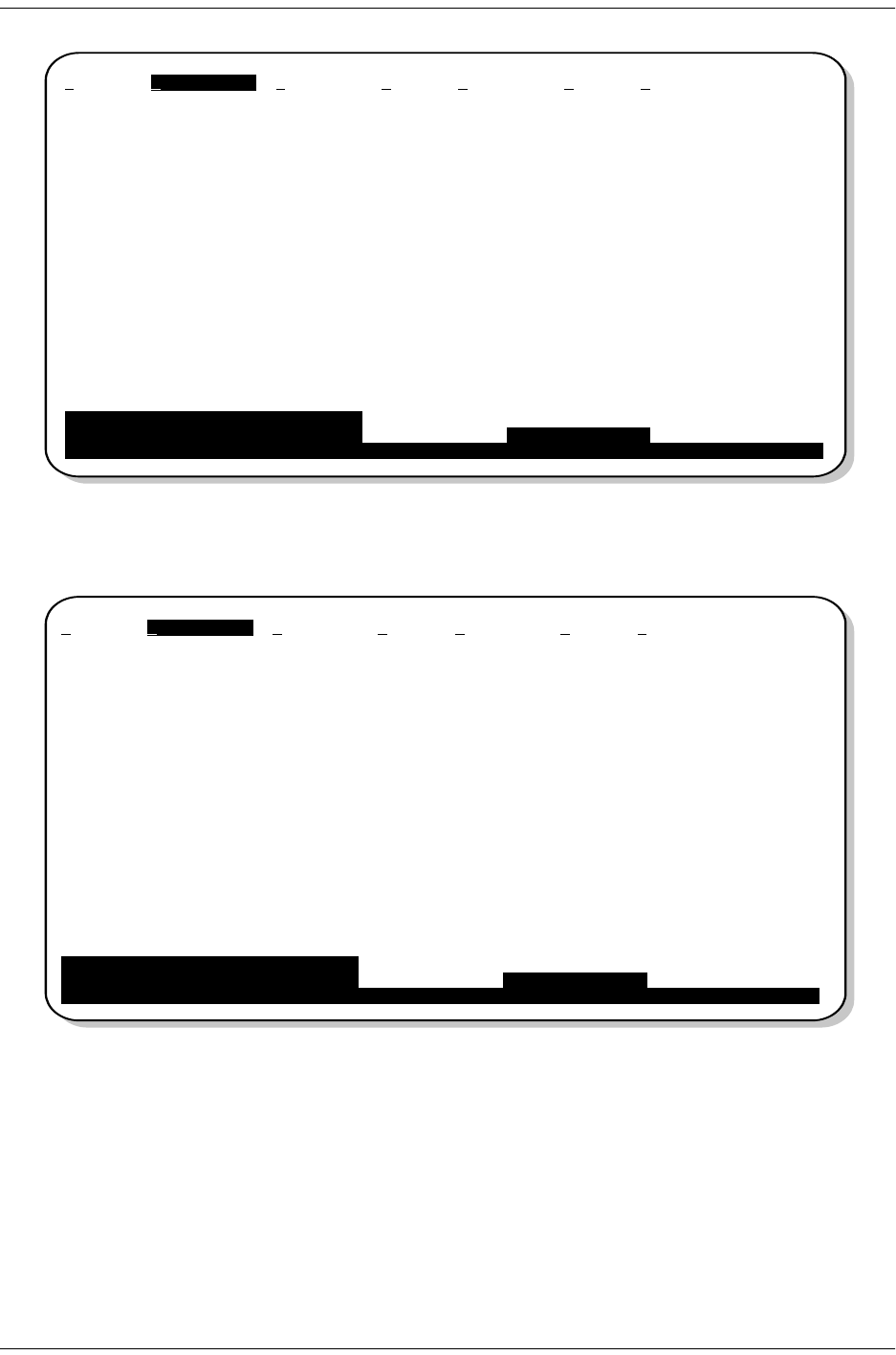
Figure 6. H2TU-C DS1 31-day Performance History
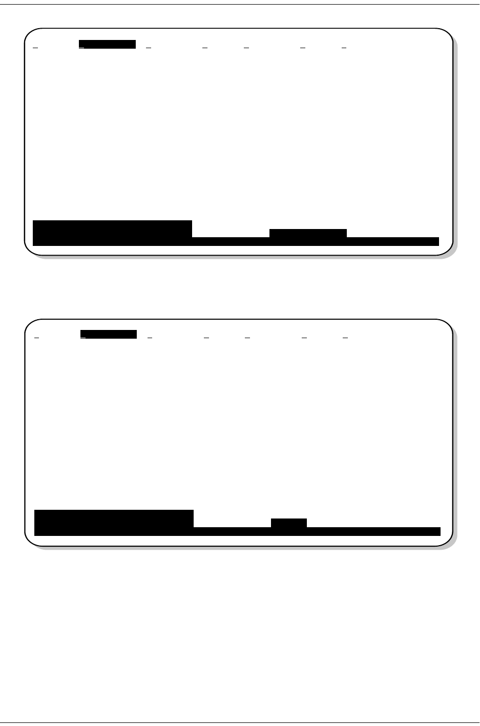
Figure 7. H2TU-R DS1 48-hour Performance History
Monitor Performance Event Log Config Inventory Rlogon Help
H2TU-C DS-1 31 Day History (Page 1 of 3)
------------------------------------------------------------------------------
Date ES-L SES-L UAS-L CV-L PDVS-L ES-P SES-P UAS-P
04/03 --------
04/04 --------
04/05 --------
04/06 --------
04/07 --------
04/08 --------
04/09 --------
04/10 --------
04/11 --------
04/12 --------
04/13 --------
04/14 141010121010 0 0
04/15 00020000
Press: (N)ext Page, (P)revious Page, C(l)ear History
------------------------------------------------------------------------------
Press <Space> to cycle through Interface : H2TU-C DS-1
choices and <Enter> to view Statistics : 31 Day History
ID: xxxx--xxxx--xxxx--xxxx 04/15/00 12:30:01 H2TU-R System: OK
___
Monitor Performance Event Log Config Inventory Rlogon Help
H2TU-R DS-1 48 Hour History (Page 1 of 4)
------------------------------------------------------------------------------
Time ES-L SES-L UAS-L CV-L PDVS-L ES-P SES-P UAS-P PRM-NE PRM-FE
23:00 ----------
1:00 ----------
2:00 ----------
3:00 ----------
4:00 ----------
5:00 ----------
6:00 ----------
7:00 ----------
8:00 ----------
9:00 ----------
10:00 ----------
11:001410101210100000
12:00 0002000000
Press: (N)ext Page, (P)revious Page, C(l)ear History
------------------------------------------------------------------------------
Press <Space> to cycle through Interface : H2TU-R DS-1
choices and <Enter> to view Statistics : 48 Hour History
ID: xxxx--xxxx--xxxx--xxxx 04/15/00 12:30:01 H2TU-R System: OK
___
Monitoring System Activity and Performance 152-402-145-02, Issue 2
14 June 16, 2000 H2TU-R-402
Figure 8. H2TU-C DS1 48-hour Performance History
Figure 9. H2TU-R DS1 25-hour Performance History
Monitor Performance Event Log Config Inventory Rlogon Help
H2TU-C DS-1 48 Hour History (Page 1 of 4)
------------------------------------------------------------------------------
Time ES-L SES-L UAS-L CV-L PDVS-L ES-P SES-P UAS-P
23:00 --------
1:00 --------
2:00 --------
3:00 --------
4:00 --------
5:00 --------
6:00 --------
7:00 --------
8:00 --------
9:00 --------
10:00 --------
11:00 141010121010 0 0
12:00 00020000
Press: (N)ext Page, (P)revious Page, C(l)ear History
------------------------------------------------------------------------------
Press <Space> to cycle through Interface : H2TU-C DS-1
choices and <Enter> to view Statistics : 48 Hour History
ID: xxxx--xxxx--xxxx--xxxx 04/15/00 12:30:01 H2TU-R System: OK
___
Monitor Performance Event Log Config Inventory Rlogon Help
H2TU-R DS-1 25 Hour History (Page 1 of 9)
------------------------------------------------------------------------------
Time ES-L SES-L UAS-L CV-L PDVS-L ES-P SES-P UAS-P PRM-NE PRM-FE
9:30 ----------
9:45 ----------
10:00 ----------
10:15 ----------
10:30 ----------
10:45 ----------
11:00 ----------
11:15 ----------
11:30 ----------
11:45 ----------
12:00 ----------
12:151410101210100000
12:30 0002000000
Press: (N)ext Page, (P)revious Page, C(l)ear History
------------------------------------------------------------------------------
Press <Space> to cycle through Interface : H2TU-R DS-1
choices and <Enter> to view Statistics : 25 Hour History
ID: xxxx--xxxx--xxxx--xxxx 04/15/00 12:30:01 H2TU-R System: OK
___
152-402-145-02, Issue 2 Monitoring System Activity and Performance
H2TU-R-402 June 16, 2000 15
Figure 10. H2TU-C DS1 25-hour Performance History
Figure 11. H2TU-R DS1 Current Statistics
Monitor Performance Event Log Config Inventory Rlogon Help
H2TU-C DS-1 25 Hour History (Page 1 of 9)
------------------------------------------------------------------------------
Time ES-L SES-L UAS-L CV-L PDVS-L ES-P SES-P UAS-P
9:30 --------
9:45 --------
10:00 --------
10:15 --------
10:30 --------
10:45 --------
11:00 --------
11:15 --------
11:30 --------
11:45 --------
12:00 --------
12:15 141010121010 0 0
12:30 00020000
Press: (N)ext Page, (P)revious Page, C(l)ear History
------------------------------------------------------------------------------
Press <Space> to cycle through Interface : H2TU-C DS-1
choices and <Enter> to view Statistics : 25 Hour History
ID: xxxx--xxxx--xxxx--xxxx 04/15/00 12:30:01 H2TU-R System: OK
___
Monitor Performance Event Log Config Inventory Rlogon Help
H2TU-R DS-1 Current Statistics
------------------------------------------------------------------------------
1 Day 1 Hour 15 Min
Start 00:00 12:00 12:30
ES-L 0 0 0
SES-L 0 0 0
UAS-L 0 0 0
CV-L 0 0 0
PDVS-L 0 0 0
ES-P 0 0 0
SES-P 0 0 0
UAS-P 0 0 0
PRM-NE 0 0 0
PRM-FE 0 0 0
B8ZSS 0 0 0
MSEC 3482 1801 1
Press: C(l)ear Current Statistics
------------------------------------------------------------------------------
Press <Space> to cycle through Interface : H2TU-R DS-1
choices and <Enter> to view Statistics : Current
ID: xxxx--xxxx--xxxx--xxxx 04/15/00 12:30:01 H2TU-R System: OK
___
Monitoring System Activity and Performance 152-402-145-02, Issue 2
16 June 16, 2000 H2TU-R-402
Table 5. Error Acronyms Used on the DS1 Performance History Screens
Error Acronym Description Error Acronym Description
ES-L Errored Seconds - Line
Seconds with BPV ≥ 1. SES-P Severely errored seconds - Path
Seconds with SES or CRC(ESF) ≥ 320 or
FE (d) (SF) ≥ 8 (FT + FS).
SES-L Severely errored seconds - Line
Seconds with BPV plus EXZ ≥ 1544 or
LOS ≥ 1.
UAS-P Unavailable seconds - Path
A second of unavailability based on SES-P
or AIS ≥ 1.
UAS-L Unavailable seconds - Line
Seconds with LOS ≥ 1. PRM-NE (a)
(a) Only appears on H2TU-R Performance History screens.
Performance Report Monitoring - Near End
The PRM from CPE indicates errors, and
the signal received from the network at the
remote is error-free.
CV-L Code Violation - Line
Total BPV count. PRM-FE (a) Performance Report Monitoring - Far End
The PRM from the network indicates
errors, and the signal received from the
CPE is error-free.
PDVS-L Pulse Density Violation Seconds - Line
Seconds with excessive zeroes
(AMI = 16 zeroes, B8ZS = 8 zeroes).
B8ZSS (b)
(b) Appears on the DS1 Current Statistics screens.
B8ZS Monitored Seconds
Seconds with B8ZS detection when AMI
option is active.
ES-P Errored Seconds - Path
Seconds with SEF (c), CRC (ESF) or
FE (d)(SF) ≥ 1.
(c) Severely Errored Frame—Two or more frame bit errors occurring in a 0.75 ms interval for SF or a 3 ms interval for ESF.
(d) FE is a frame bit error.
MSEC (b) Monitored Seconds of the current
(15-minute/1-hour/1-day) screen.
152-402-145-02, Issue 2 Monitoring System Activity and Performance
H2TU-R-402 June 16, 2000 17
Performance History at the HDSL2 Interface
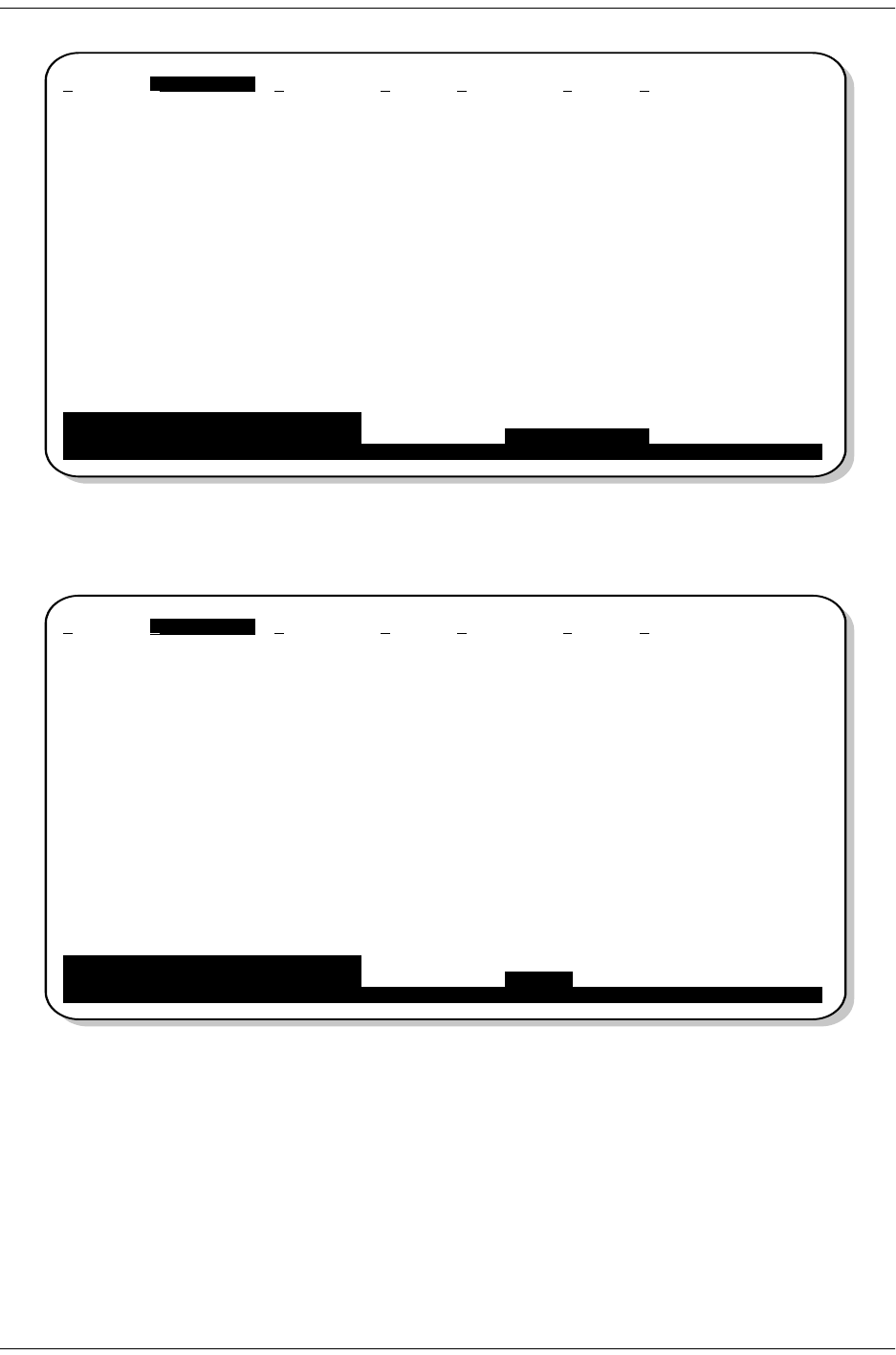
Figure 12 is an example of a 31-Day History screen for the H2TU-R HDSL2 interface. The HDSL2 interface has
31-day, 48-hour, 25-hour, and current statistic screens for the H2TU-R and H2TU-C. Table 6 on page 19 describes
the kinds of errors reported for these screens.
Figure 12. H2TU-R HDSL2 31-day Performance History
Figure 13. H2TU-R HDSL2 48-hour Performance History
Monitor Performance Event Log Config Inventory Rlogon Help
H2TU-R HDSL2 31 Day History (Page 1 of 3)
------------------------------------------------------------------------------
Date ES SES UAS CV LOSWS
04/03 ---- -
04/04 ---- -
04/05 ---- -
04/06 ---- -
04/07 ---- -
04/08 ---- -
04/09 ---- -
04/10 ---- -
04/11 ---- -
04/12 ---- -
04/13 ---- -
04/14 ---- -
04/15 14 10 14 10 10
Press: (N)ext Page, (P)revious Page, C(l)ear History
------------------------------------------------------------------------------
Press <Space> to cycle through Interface : H2TU-R HDSL2
choices and <Enter> to view Statistics : 31 Day History
ID: xxxx--xxxx--xxxx--xxxx 04/15/00 12:30:01 H2TU-R System: OK
___
Monitor Performance Event Log Config Inventory Rlogon Help
H2TU-R HDSL2 48 Hour History (Page 1 of 4)
------------------------------------------------------------------------------
Time ES SES UAS CV LOSWS
23:00 ---- -
1:00 ---- -
2:00 ---- -
3:00 ---- -
4:00 ---- -
5:00 ---- -
6:00 ---- -
7:00 ---- -
8:00 ---- -
9:00 ---- -
10:00 ---- -
11:00 14 10 12 10 10
12:00 0002 0
Press: (N)ext Page, (P)revious Page, C(l)ear History
------------------------------------------------------------------------------
Press <Space> to cycle through Interface : H2TU-R HDSL2
choices and <Enter> to view Statistics : 48 Hour History
ID: xxxx--xxxx--xxxx--xxxx 04/15/00 12:30:01 H2TU-R System: OK
___
Monitoring System Activity and Performance 152-402-145-02, Issue 2
18 June 16, 2000 H2TU-R-402
Figure 14. H2TU-R HDSL2 25-hour Performance History
Figure 15. H2TU-R HDSL2 Current Statistics
Monitor Performance Event Log Config Inventory Rlogon Help
H2TU-R HDSL2 25 Hour History (Page 1 of 9)
------------------------------------------------------------------------------
Time ES SES UAS CV LOSWS
9:45 ---- -
10:00 ---- -
10:15 ---- -
10:30 ---- -
10:45 ---- -
11:00 ---- -
11:15 ---- -
11:30 ---- -
11:45 ---- -
12:00 ---- -
12:15 14 10 12 10 10
12:30 0000 0
12:45 0002 0
Press: (N)ext Page, (P)revious Page, C(l)ear History
------------------------------------------------------------------------------
Press <Space> to cycle through Interface : H2TU-R HDSL2
choices and <Enter> to view Statistics : 25 Hour History
ID: xxxx--xxxx--xxxx--xxxx 04/15/00 12:30:01 H2TU-R System: OK
___
Monitor Performance Event Log Config Inventory Rlogon Help
H2TU-R HDSL2 Current Statistics
------------------------------------------------------------------------------
1 Day 1 Hour 15 Min
Start 00:00 12:00 12:30
ES 0 0 0
SES 0 0 0
UAS 0 0 0
CV 0 0 0
LOSWS 3482 1801 1
Margin(dB) LA (dB)
Hi 16
Cur 15 25
Low 12
Press: C(l)ear Current Statistics
------------------------------------------------------------------------------
Press <Space> to cycle through Interface : H2TU-R HDSL2
choices and <Enter> to view Statistics : Current
ID: xxxx--xxxx--xxxx--xxxx 04/15/00 12:30:01 H2TU-R System: OK
___
152-402-145-02, Issue 2 Monitoring System Activity and Performance
H2TU-R-402 June 16, 2000 19
USING THE PERFORMANCE SCREENS TO VIEW ALARM DATA
To access the alarm history screens:
1Press to select the Performance menu.
2Press the to select an interface (H2TU-C DS1, H2TU-R DS1, H2TU-C HDSL2, or H2TU-R
HDSL2), then press .
3Press the until Alarm History is selected, then press .
4Press or to page through the alarm history screens.
5Press to clear the selected alarm history screen.
Alarm History at the DS1 Interface
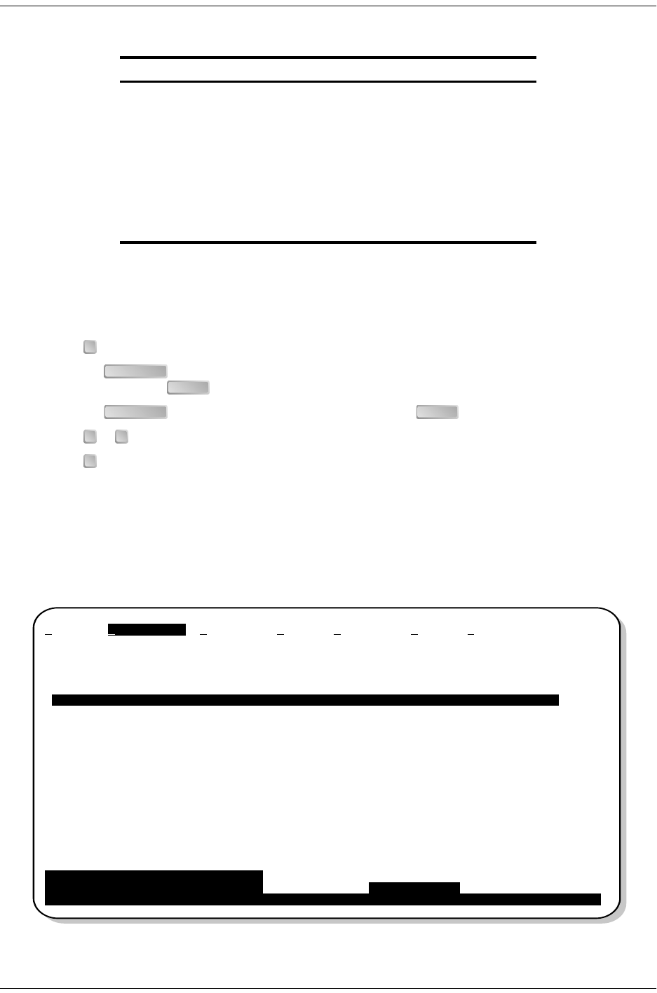
Figure 16 below and Figure 17 on page 20 are examples of Alarm History screens for the H2TU-R DS1 interface
and the H2TU-C DS1 interface, respectively. Current alarms are shown in reverse video. The types of alarms
reported for the H2TU-R are described in Table 7 on page 20.
Figure 16. H2TU-R DS1 Alarm History Screen
Table 6. Error Acronyms Used on the HDSL2 Performance History Screens
Error Acronym Description
ES Errored seconds
Seconds with HDSL2 CRC ≥1 or LOSW ≥1
SES Severely errored seconds
Seconds with HDSL2 CRC ≥50 or LOSW ≥1
UAS Unavailable seconds
Based on 10 contiguous SES occurrences
CV Code Violation
Total count of HDSL2 CRC errors.
LOSWS Loss of Sync Word Second
Seconds with LOSW ≥1
P
SPACEBAR ENTER
SPACEBAR ENTER
N P
L
Monitor Performance Event Log Config Inventory Rlogon Help
H2TU-R DS-1 Alarm History
------------------------------------------------------------------------------
Alarm First Last Status Count
RLOS 03/16/00 00:00 04/15/00 00:45 ALARM 12
RAIS OK 0
RAI OK 0
TX RAI-CI OK 0
PRM-NE OK 0
PRM-FE OK 0
DBER 03/16/00 00:37 04/15/00 00:47 OK 7
Press: C(l)ear Alarm History
------------------------------------------------------------------------------
Press <Space> to cycle through Interface : H2TU-R DS-1
choices and <Enter> to view Statistics : Alarm History
ID: xxxx--xxxx--xxxx--xxxx 04/15/00 12:30:01 H2TU-R System: Alarm
Monitoring System Activity and Performance 152-402-145-02, Issue 2
20 June 16, 2000 H2TU-R-402
Figure 17. H2TU-C DS1 Alarm History Screen
Table 7. H2TU-R DS1 Alarm Descriptions
Screen Alarm Front-Panel Alarm Description
RLOS RLOS Remote Loss of Signal— Loss of the H2TU-R DS1 input signal.
RAIS RAIS Remote Alarm Indication Signal—Indicates an AIS (all ones) pattern is being received at
the H2TU-R DS1 input port. By default AIS-CI (a) is sent towards the network.
(a) AIS-CI is a modified AIS alarm pattern. Equipment not suited to detect AIS-CI still detects this signal as an AIS. AIS-CI is sent
toward the network indicating that an LOS (RLOS) or AIS (RAIS) has been received from the CPE.
RAI RRAI Remote RAI - Remote Alarm Indication at the H2TU-R—Indicates an RAI alarm (yellow)
from the CPE with errors from the line unit or network.
TX RAI-CI TRCI Transmit RAI-CI - Remote Alarm Indication at the H2TU-R—Upon reception of an RAI
(yellow alarm) from the CPE, the H2TU-R sends a RAI-CI towards the network if the
network signal received at the H2TU-R is clear. If the network signal is impaired (LOS, AIS
or LOF), then the RAI is passed on to the network unaltered. This is applicable to SF or
ESF framing. In an all SF environment, RACI must be enabled to convert SF RAI to SF
RAI-CI.
PRM-NE PRMN Performance Report Monitoring - Near End—The count of the PRM-NE register at the
H2TU-R exceeds the 10-6 BER threshold at 648 events since 12:00:00 AM.
PRM-FE PRMF Performance Report Monitoring - Far End—The count of the PRM-FE register at the
H2TU-R exceeds the 10-6 BER threshold at 648 events since 12:00:00 AM.
DBER DBER Bit Error Rate—The DS1 BER has exceeded the built-in 24-hour threshold limits of
approximately 10-6.
Monitor Performance Event Log Config Inventory Rlogon Help
H2TU-C DS-1 Alarm History
------------------------------------------------------------------------------
Alarm First Last Status Count
LLOS 04/10/00 00:00 04/15/00 00:45 ALARM 12
LAIS OK 0
DBER 04/10/00 00:37 04/10/00 00:45 OK 7
Press: C(l)ear Alarm History
------------------------------------------------------------------------------
Press <Space> to cycle through Interface : H2TU-C DS-1
choices and <Enter> to view Statistics : Alarm History
ID: xxxx--xxxx--xxxx--xxxx 04/15/00 12:30:01 H2TU-C System: Alarm
152-402-145-02, Issue 2 Monitoring System Activity and Performance
H2TU-R-402 June 16, 2000 21
Alarm History at the HDSL2 Interface
Figure 18 and Figure 19 are examples of Alarm History screens for the H2TU-R HDSL2 interface and the
H2TU-C HDSL2 interface, respectively. Current alarms are shown in reverse video. The types of alarms reported
for the H2TU-R are described in Table 8 on page 22.
Figure 18. H2TU-R HDSL2 Alarm History Screen
Figure 19. H2TU-C HDSL2 Alarm History Screen
Monitor Performance Event Log Config Inventory Rlogon Help
H2TU-R HDSL2 Alarm History
------------------------------------------------------------------------------
Alarm First Last Status Count
LOSW 03/16/00 00:00 04/15/00 00:45 ALARM 12
MAL OK 0
LA OK 0
HBER 03/16/00 00:37 04/15/00 00:45 OK 7
Press: C(l)ear Alarm History
------------------------------------------------------------------------------
Press <Space> to cycle through Interface : H2TU-R HDSL2
choices and <Enter> to view Statistics : Alarm History
ID: xxxx--xxxx--xxxx--xxxx 04/15/00 12:30:01 H2TU-R System: Alarm
Monitor Performance Event Log Config Inventory Rlogon Help
H2TU-C HDSL2 Alarm History
------------------------------------------------------------------------------
Alarm First Last Status Count
LOSW 04/10/00 00:00 04/15/00 00:45 ALARM 12
MAL OK 0
LA OK 0
HBER 04/10/00 00:37 04/10/00 00:45 OK 7
SHORT OK 0
GND OK 0
OPEN OK 0
Press: C(l)ear Alarm History
------------------------------------------------------------------------------
Press <Space> to cycle through Interface : H2TU-C HDSL2
choices and <Enter> to view Statistics : Alarm History
ID: xxxx--xxxx--xxxx--xxxx 04/15/00 12:30:01 H2TU-C System: Alarm
Monitoring System Activity and Performance 152-402-145-02, Issue 2
22 June 16, 2000 H2TU-R-402
USING THE EVENT LOG TO TRACK SYSTEM EVENTS
To view a running log of system events, press to select the Event Log. The Event Log displays the date and
time of the 100 most recent events (most recent displayed first) and provides a description of each event. See
Table 9 on page 23 for a complete list of event log messages.
•Press or to page through the event log.
•Press to return to the top of the log.
•Press to clear the event log.
Figure 20. System Event Log
Table 8. H2TU-R HDSL2 Alarm Descriptions
Screen Alarm Front-Panel Alarm Description
LOSW LOSW Loss of Sync Word—The HDSL2 loop has lost synchronization.
MAL MAL Margin—The margin on the HDSL2 loop has dropped below the minimum threshold
value set for the system.
LA LA Loop Attenuation—The attenuation on the HDSL2 loop has exceeded the maximum value
set for the HDSL2 loop attenuation threshold.
HBER HBER Block Error Rate—The HDSL2 BER has exceeded the set threshold limits of 10-6 or 10- 7.
E
N P
T
L
Monitor Performance Event Log Config Inventory Rlogon Help
System Event Log (Page 1 of 7)
------------------------------------------------------------------------------
# Location Date and Time Entry
1 System 04/10/00 12:25:00 DS1 Alarm Register reset
2 System 04/10/00 12:25:00 HDSL2 Alarm Register Reset
3 System 04/10/00 12:25:00 DS1 Performance Register Reset
4 System 04/10/00 12:25:00 HDSL2 Performance Register Reset
5 System 04/10/00 00:13:32 Time set 12:25:00
6 System 04/10/00 00:13:27 Date set 10/21/99
7 H2TU-C 04/03/00 00:13:27 NLOC: Loop-down
8 H2TU-C 04/03/00 00:11:16 NLOC: Loop-up
9 H2TU-R 04/03/00 00:10:43 DS1 LOS Alarm: End
10 H2TU-R 04/03/00 00:10:30 DS1 LOS Alarm: Begin
11 System 04/03/00 00:04:11 DS1C: AUTO to AMI
12 H2TU-C 04/03/00 00:00:40 HDSL2 LOSW Alarm: End
13 H2TU-C 04/03/00 00:00:02 HDSL2 LOSW Alarm: Begin
14 - Empty -
15 - Empty -
Press: (N)ext Page, (P)revious Page, (T)op of Log, C(l)ear Log
ID: xxxx--xxxx--xxxx--xxxx 04/15/00 12:30:01 H2TU-R System: OK
___

152-402-145-02, Issue 2 Monitoring System Activity and Performance
H2TU-R-402 June 16, 2000 23
Table 9. Event Log Messages
Event Log Messages
DS1 Alarm History reset
DS1 PM register reset
HDSL2 Alarm History reset
HDSL2 PM register reset
Loop Down (any segment)
Loop Up (any segment)
Provisioning option change: <provisioning mnemonic>: changed from <old> to <new>
CPE DBER alarm (1-day threshold crossed of any PM data except PRM-NE or PRM-FE)
CPE DS1 AIS begins/ends
CPE DS1 LOS begins/ends
CPE PRM-NE BER alarm (at the remote only: 1-day threshold crossed of PRM-NE: trouble on CPE receive)
Current statistics reset
Event Log reset
H2TU-C Power up/down
H2TU-R Power up/down
HDSL2 DC pair open begins/ends on any segment
HDSL2 Ground fault begins/ends on any segment
HDSL2 HBER alarm (threshold crossed) on any segment.
HDSL2 loop attenuation (threshold crossed) on any HDSL2 I/F
HDSL2 margin alarm (threshold crossed) on any HDSL2 I/F
HDSL2 unavailability begins/ends on any segment
Master zero reset
NTWK DBER alarm (1-day threshold crossed of any PM data)
NTWK DS1 LOS begins/ends
NTWK PRM-FE BER alarm (at the remote only: 1-day threshold crossed of PRM-FE: trouble on NTWK far end)
NTWN DS1 AIS begins/ends
Power Feed Open begins/ends
Power Feed Short begins/ends
RAI begins/ends
TX RAI-CI begins/ends (RAI-CI sent from the remote towards the network)
Loopback Operation 152-402-145-02, Issue 2
24 June 16, 2000 H2TU-R-402
LOOPBACK OPERATION
HiGain HDSL2 has a family of loopback options for analyzing circuit functionality. The loopback signal is
transmitted and returned to the sending device for comparison. This allows you to verify the integrity of the
HDSL2 channels to the H2TU-C, the H2TU-C DSX-1 interface, and the DS1 channels to the customer. Loopback
options include:
•Generic Loopback (GNLB) options, including the SmartJack (SMJK) option (see Table 10 on page 25)
•Special Loopback (SPLB) options (see “Special Loopback Commands” on page 26) and the following
command tables:
–Addressable Repeater Loopback command: A2LB (see Table 11 on page 28)
–Addressable Repeater Loopback commands: A3LB, A4LB (see Table 12 on page 30)
Loopbacks can be initiated by:
•Selecting the loopback type using the MODE and SEL buttons on the H2TU-C front panel
•Selecting the NREM-CLOC dual loopback using the LBK button on the H2TU-R front panel
•Selecting the loopback type from the Monitor screen when connected to the H2TU-C or H2TU-R craft port
•Entering the loopback code into the test set connected to the craft port of the H2TU-C or H2TU-R
Generic Loopback Commands
The HiGain HDSL2 Generic Loopback (GNLB) commands allow you to use inband codes to loop up either
NLOC (4-in-7) or NREM (3-in-7) towards the network. In addition, these inband codes loop up CREM (6-in-7)
or CLOC (5-in-7) towards the customer. Either loopup condition can be terminated (looped down) with the 3-in-5,
SMJK loopdown code. All inband codes must be present for at least 5 seconds before the HiGain HDSL2 system
responds. TLOS is a logic loopback caused by loss of the DS1 input from the CI.
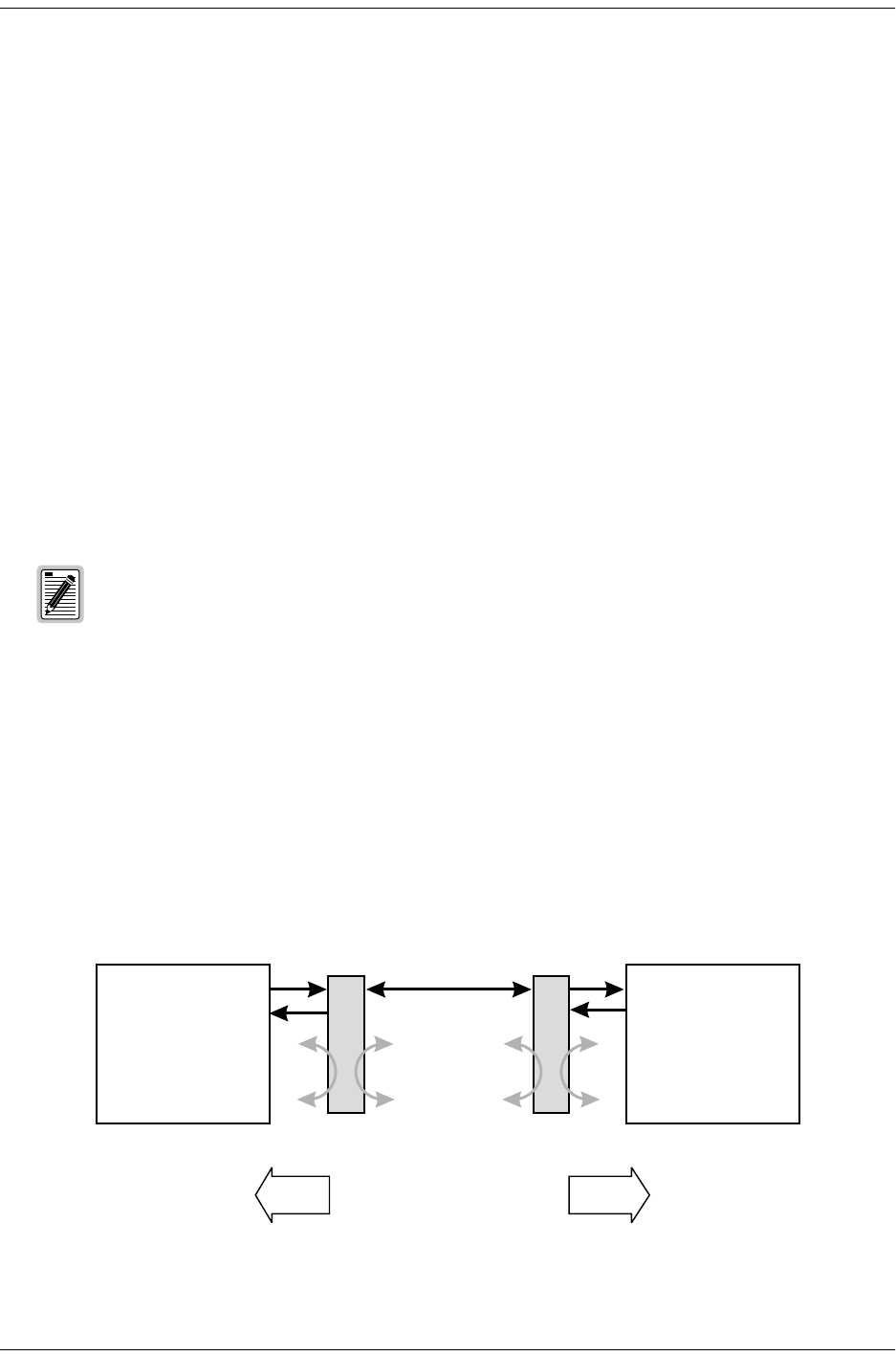
Figure 21 summarizes the available loopbacks in the system, and Table 10 on page 25 summarizes the HiGain
HDSL2 generic loopback commands. See “GNLB Test Procedures” on page 26 for the test procedures that apply
when using the GNLB mode.
Figure 21. Loopback Summary
The H2TU-R-402 List 4E performs a metallic loopback self test when looping up an NREM or
SMJK loopback.
HiGain HDSL2 supports multiple loopbacks, but a single loopback is the preferred method.
Network Customer
Premises
Activate loopback using
one of the following:
• MODE/SEL pushbuttons
• Maintenance Terminal
•Test Set
Activate loopback using
one of the following:
• LBK pushbutton
• Maintenance Terminal
•Test Set
H2TU-C H2TU-R
NLOC NREM
SMJK
TLOS
CREM CLOC
152-402-145-02, Issue 2 Loopback Operation
H2TU-R-402 June 16, 2000 25
Table 10. Summary of HiGain HDSL2 Loopback Codes and Activation Methods
Method of Activation
Loopback Code Description Test Set Craft Port H2TU-C
MODE/SEL
NLOC 1111000
4-in-7 DSX-1 signal is looped back to the network at the H2TU-C. X X X
NREM 1110000
3-in-7 DSX-1 signal is looped back to the network at the H2TU-R. X X X
CLOC 1111100
5-in-7 DS1 signal from the customer is looped back to the
customer at the H2TU-R. X X X
CREM 1111110
6-in-7 DS1 signal from the customer is looped back to the
customer at the H2TU-C. X X X
COLB Dual loopback at H2TU-C. DSX-1 signal is looped back to
the network at the H2TU-C and DS1 signal from the
customer is looped back to the customer at the H2TU-C. X X
RULB Dual loopback at H2TU-R. DSX-1 signal is looped back to
the network at the H2TU-R and DS1 signal from the
customer is looped back to the customer at the H2TU-R. XX (a)
SMJK LpUp
(PL) 11000
2-in-5 SmartJack Loopup or NID payload (PL) code. Invokes
H2TU-R loopback towards network. X
SMJK LpUp
(ESF-DL) 1111-1111-
0100-1000 SmartJack Loopup or NID (ESF-DL) code. Invokes
H2TU-R loopback towards network. X
SMJK LpDn
(PL) 11100
3-in-5 SmartJack Loopdown or NID payload (PL) code. Removes
SMJK, NLOC, NREM, CLOC, CREM, CRGx, and NRGx.X
SMJK LpDn
(ESF-DL) 1111-1111-
0010-0100 SmartJack Loopdown or NID (ESF-DL) code. Removes
SMJK, NLOC, NREM, CLOC, CREM, CRGx, and NRGx.X
(a) The RULB dual loopback (same as NREM-CLOC) can be activated by pressing the LBK button on the H2TU-R front panel.
HiGain HDSL2 systems feature the SmartJack (SMJK) option which can emulate a Network
Interface Device (NID) for the purpose of loopback testing of the HiGain HDSL2 circuit. SMJK
and NREM loopbacks perform the same functions, but their initiation differs. SMJK indicates
that the loopback was initiated by the 2-in-5 inband command. NREM, on the other hand, is
initiated by the 3-in-7 inband command, by the H2TU-R front panel LBK button, by a command
issued from the maintenance terminal, or by the H2TU-C front panel MODE and SEL buttons.
Use the inband commands to enable or disable the SMJK loopback options. The HiGain HDSL2
system setting is normally enabled to recognize all inband SMJK loopback commands.

Loopback Operation 152-402-145-02, Issue 2
26 June 16, 2000 H2TU-R-402
Special Loopback Commands
In addition to the GNLB loopback command mode, a HiGain HDSL2 system can be configured for one of three
special loopback command modes. These command modes, A2LB, A3LB, and A4LB, are selected from the ADC
Options maintenance terminal screen or by using the MODE and SEL buttons on the H2TU-C front panel. Once
a loopback mode is activated, other loopback commands can be sent by a test set connected to the craft port on
the H2TU-C or H2TU-R front panel.
A2LB through A4LB are special, addressable, repeater loopback modes that are supported by the H2TU-R-402
(see Table 11 on page 28 and Table 12 on page 30 for list of Addressable Repeater Loopback Commands). These
loopback modes provide the HiGain HDSL2 system with sophisticated maintenance and troubleshooting tools.
A2LB is patterned after the Teltrend addressable T1 repeater loopbacks. A3LB and A4LB are patterned after the
Wescom addressable T1 repeater loopbacks.
These addressable repeater loopback modes have been enhanced to handle the specific requirements of the
following HiGain HDSL2 customers:
•A2LB (Teltrend) = Southwestern Bell
•A3LB (Wescom) = New England Telephone, Bell Atlantic
•A4LB (Wescom Mod 1) = New York Telephone
A2LB can be configured to do one of the following:
•Block the arming code (after 2 seconds) from exiting the H2TU-C into the network, and replace it with the
AIS code.
•Unblock the AIS code by executing the Far End Activate code.
A3LB differs from A4LB in that A3LB supports the additional (1-in-6) SMJK loopback command.
LOOPBACK TEST PROCEDURES
The following sections provide step-by-step test procedures for verifying the integrity of the HDSL2 channels at
every module location as well as the DS1 channels to the customer and the local DSX-1 interface.
GNLB Test Procedures
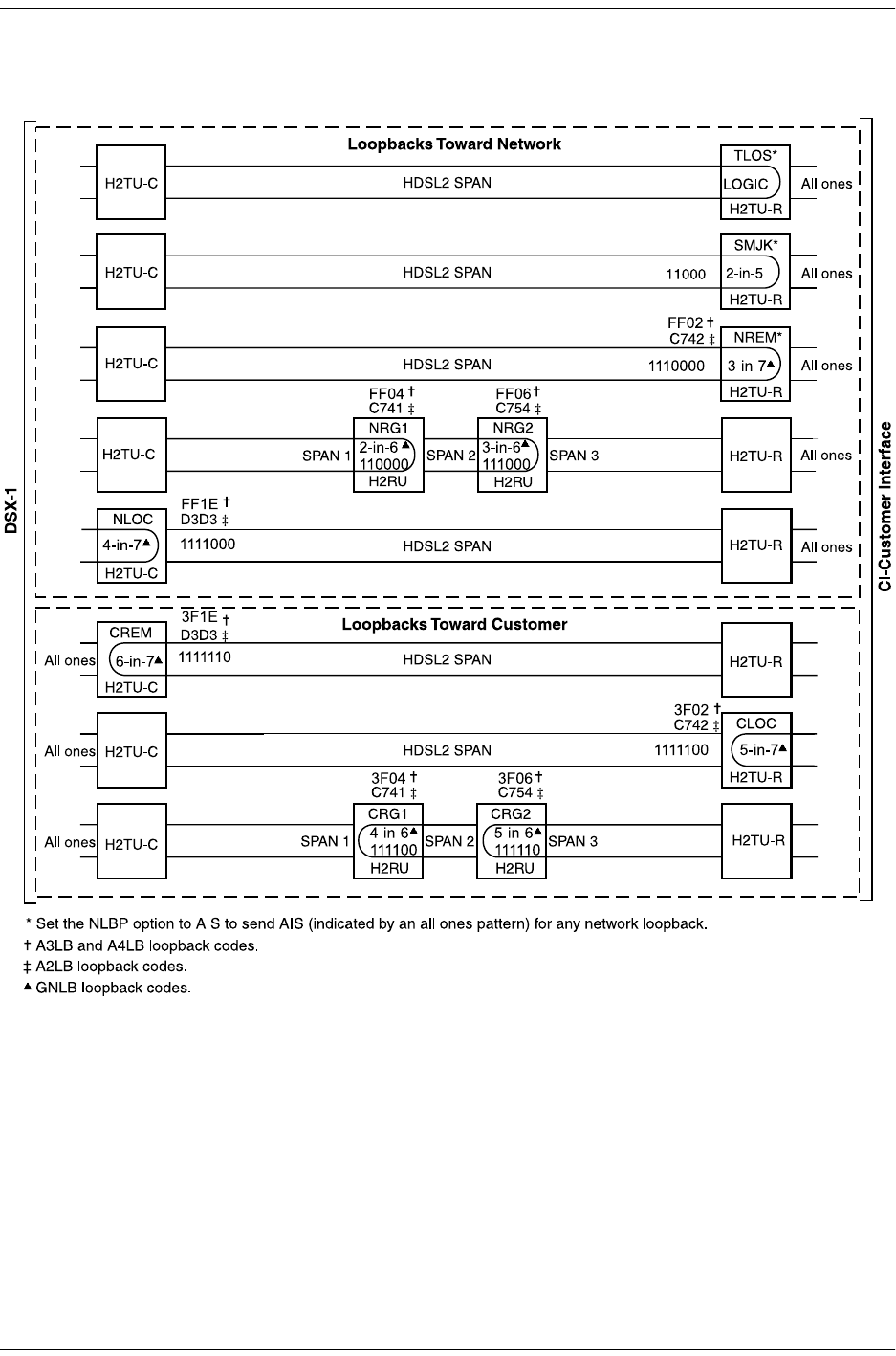
Figure 22 on page 27 is a graphical representation of the various loopback configurations with the associated
GNLB commands shown. Also, refer to Table 10 on page 25 for a description of these commands.
To perform the GNLB loopback test procedure:
1Have the CO tester send the NREM (3-in-7) inband loopup code for 5 seconds. The LBK LED on the front
panel should be a steady yellow, and the loopback mode should be identified on the Monitor screen.
2Have the CO tester transmit a DS1 test signal towards the H2TU-R-402 and verify that the returned (looped)
signal to the test set is error-free.
3If step 2 fails, have the CO tester transmit the 3-in-5 inband loopdown code.
4Have the CO tester send the NLOC (4-in-7) inband loopup for 5 seconds. You should be able to observe the
NLOC message on the Monitor screen.
SMJK loopback commands are only activated by inband commands.
152-402-145-02, Issue 2 Loopback Operation
H2TU-R-402 June 16, 2000 27
5Repeat Step 2. If the test passes, the problem is in the downstream direction. If it fails, the problem is in the
upstream direction.
Figure 22. Loopback Modes
Loopback Operation 152-402-145-02, Issue 2
28 June 16, 2000 H2TU-R-402
A2LB Test Procedures
Using the codes listed in Table 11, a network tester can activate NLOC, NRG or NREM loopbacks (or SMJK, if
enabled). A tester at the customer premises can activate CLOC, CRG, or CREM loopbacks.
To perform the A2LB test procedures:
1Send the inband Arming and NI LPBK code 11000 to the H2TU-R-402 for at least 5 seconds.
2Monitor the output of the H2TU-R-402 for the return of the pattern. Return of the pattern indicates one of the
following:
•The H2TU-R has looped up (if the SMJK Loopback option is enabled)
•An external NID has looped up (if the SMJK Loopback option is disabled), and the H2TU-C and
H2TU-R have been armed.
3Verify, if possible, that the H2TU-R LBK LED is either flashing yellow at 4-second intervals (indicating that
the system is armed), or is a steady yellow (indicating that it is both armed and in SMJK loopback). The
H2TU-C Status LED also flashes yellow when the system is armed.
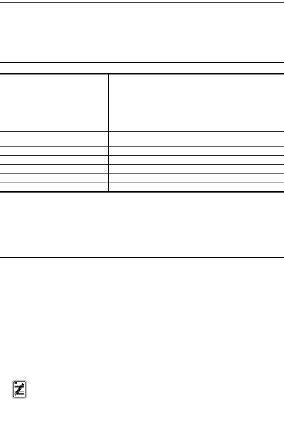
Table 11. Addressable Repeater Loopback Commands (A2LB)
Name Description Binary Code (a) (Hexadecimal Equivalent)
(a) The leftmost bit arrives first in all sequences. The detection algorithm functions reliably with a random 10-3 BER on the facility.
The entire arming and loopback sequence can also be initiated at the remote H2TU-R location.
ARMING or NI LPBK (inband) Arming code 11000-11000 ...
ARMING or NI LPBK (ESF Datalink) Arming code 1111-1111-0100-1000 (FF48)
IR LPDN or DISARM (inband) Disarming code 11100-11100 ...
IR LPDN or DISARM (ESF Datalink) Disarming code 1111-1111-0010-0100 (FF24)
IOR LPBK (NLOC and CREM)
230-232 bit errors
229-231 bit errors (b)
(b) The H2TU-R identifies CREM (and the H2TU-C identifies NLOC) with 231 bit errors, including the frame bits. When framed
data is being sent in the Auto framing mode, the number of the 231 bit errors detected by the test set varies from 229 to 231,
depending on whether or not the test set counts frame errors as bit errors and on the number of frame bits contained in the
block of 231 error bits. The H2TU-R and H2TU-C generate this bit pattern in a series of discontinuous bursts containing 20-bit
errors each, including frame bits. Those test sets that do not count frame error bits as data bit errors will indicate fewer bits
than the H2TU-R and H2TU-C transmit for a CI and NI loopback.
H2TU-C loopup 1101-0011-1101-0011 (D3D3)
IR LPDN Loopdown (H2TU-C, H2RU, or
H2TU-R) 1001-0011-1001-0011 (9393)
IR QUERY LPBK Query loopback 1101-0101-1101-0101 (D5D5)
IR ALTERNATE QUERY LPBK Alternate query loopback 1101-0101-1110-1010 (D5EA)
TIME-OUT OVERRIDE Loopback time-out override 1101-0101-1101-0110 (D5D6)
FAR END NI ACTIVATE Unblock AIS 1100-0101-0101-0100 (C554)
IOR POWER DOWN (H2TU-C) (c)
(c) The IOR Power Down code must remain present for the duration of the powerdown mode. When this code is removed, the
HiGain HDSL2 system returns to its normal unlooped and unarmed state.
Removes HDSL2 line power 0110-0111-0110-0111 (6767)
If the Arming code is not returned after 5 seconds, the system may be armed but there is no
active loopback.

152-402-145-02, Issue 2 Loopback Operation
H2TU-R-402 June 16, 2000 29
4Once armed, the H2TU-R-402 can be looped back by sending Intelligent Office Repeater (IOR) LPBK
activation code 1101-0011-1101-0011 (D3D3) for at least 5 seconds. You should observe the following
activation response pattern:
a2 seconds of AIS (all ones pattern)
b2 seconds of returning data pattern
cLogic errors (including the frame bit) occurring in the returned pattern comprising:
–231 errors, if IOR LPBK (H2TU-R-402) was sent
–20 errors, if ILR-2 (H2TU-R) was sent
dNormal looped data
This error pattern repeats every 20 seconds as long as the IOR loopback pattern is being sent. This also applies
to ILR, Time-out Override, and Query commands.
The H2TU-C is now in logic loopback if the IOR NLOC loopback command was sent. The Time-out
Override command or a Loopdown command can override the selection made for the loopback time-out. If
the Time-out Override code 1101-0101-1101-0110 (D5D6) is received after activating a loopback, then the
automatic timed expiration of the loopback is inhibited. If this Time-out Override is sent, then the only way
to loop the H2TU-R-402 down is to do one of the following:
•Issue the IR loopdown (LPDN) code 1001-0011-1001-0011 (9393)
•Issue the NI LPDN and Disarm inband code 11100 or the ESF-DL code (FF24).
5Once the test is complete, do one of the following:
•If the system is to loop down but remain Armed, send the IR LPDN code.
•If all the equipment is to be looped down, disarmed, and returned to normal operation, send the disarm
inband code 11100 or the ESF-DL code (FF24).
The Time-out Override function is only valid for the current active loopback. The automatic
time-out timer is restored during subsequent loopback sessions.
The Armed mode has an automatic time-out of 120 minutes, but this timer is reset to 120 for any
of the following events:
•Loopback terminates (manually or time-out)
•Query
•Alternate query
•Far End activate
•Another ARM command
This timer is inhibited while any of the valid command codes are being sent. Once the codes
are removed, the timer restarts at 120.
Loopback Operation 152-402-145-02, Issue 2
30 June 16, 2000 H2TU-R-402
A3LB and A4LB Test Procedures
The H2TU-C can be looped back by sending the Addressable Office Repeater (AOR) LPBK activation code
1111-1111-0001-1110 (FF1E) for at least 5 seconds. This causes the H2TU-R-402 to enter the NLOC state. The
H2TU-C Loopback Time-out (LBTO) setting determines the duration of this loopback unless it is overridden by
the reception of a second identical 16-bit loopup command before the timer expires. When this time-out override
state exists, the only way to loop the H2TU-R-402 down is to issue one of the three loopdown commands listed
in Table 12. The automatic time-out mode is restored during subsequent loopback sessions.
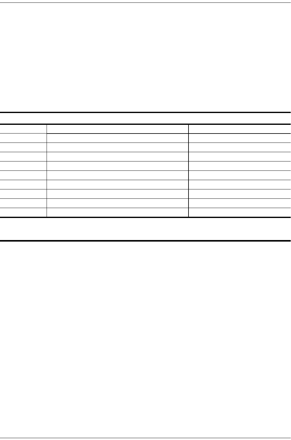
Table 12 summarizes the codes required to execute Addressable 3 (A3LB) and Addressable 4 (A4LB) repeater
loopback commands. All code sequences must be present for at least 5 seconds.
Table 12. Addressable Repeater Loopback Commands (A3LB and A4LB)
Name Description Binary Code (a) (Hexadecimal Equivalent)
(a) The leftmost bit arrives first in all sequences. The detection algorithm functions reliably with a random 10-3 Bit Error Ratio (BER)
on the facility. The entire arming and loopback sequence can also be initiated at the remote H2TU-R location.
NLOC H2TU-R-402 loopup from NI 1111-1111-0001-1110 (FF1E)
CREM H2TU-R-402 loopup from CI 0011-1111-0001-1110 (3F1E)
NREM H2TU-R loopup from NI 1111-1111-0000-0010 (FF02)
CLOC H2TU-R loopup from CI 0011-1111-0000-0010 (3F02)
SMJK H2TU-R loopup from NI 11000-11000-11000 ...
SMJK H2TU-R loopup from NI (b)
(b) Not supported by A4LB.
100000 100000 100000 ...
SMJK H2TU-R loopup from NI (ESF-DL) 1111-1111-0100-1000 (FF48)
Loopdown H2TU-C and H2TU-R loopdown from NI OR CI 11100-11100-11100 ...
Loopdown H2TU-C and H2TU-R loopdown from NI OR CI 100-100-100 ...
Loopdown H2TU-C and H2TU-R loopdown from NI OR CI (ESF-DL) 1111-1111-0010-0100 (FF24)

152-402-145-02, Issue 2 Appendix A - Specifications
H2TU-R-402 June 16, 2000 31
APPENDIX A - SPECIFICATIONS
Power
HDSL2 Span Voltage -180 Vdc
Line or Local Power Consumption 5 W
Electrical Protection Secondary surge and power cross-protection on all DS1 and HDSL2 ports.
Environmental
Operating Temperature -40 °F to +149 °F (-40 °C to +65 °C)
Operating Humidity 5% to 95% (non-condensing)
Physical
Height 5.56 in. (14.12 cm)
Width 0.69 in. (1.75 cm)
Depth 5.87 in. (14.91 cm)
Weight 6.4 oz. (0.18 kg)
Mounting 400 or 200 mechanics
HDSL2
Line Rate 1.552 Mbps Overlapped Pulse Amplitude Modulation Transmission with Interlocking
Spectra (OPTIS)
Transmission Full duplex
Media One non-loaded, copper, two-wire cable pair
Output +16.5 dBm ±0.5 dB at 135 Ω (0-350 kHz) at remote side;
+16.8 dBm ±0.5 dB at 135 Ω (0-450 kHz) at CO side
Line Impedance 135 Ω
Maximum Loop Attenuation 35 dB at 196 kHz, 135Ω
Start-up Time 30 sec. (typical), 1 min. (maximum)
DS1
DS1 Line Impedance 100 Ω
DS1 Line Rate 1.544 Mbps ±200 bps
DS1 Line Format Alternate Mark Inversion (AMI) or Bipolar with 8-Zero Substitution (B8ZS)
DS1 Frame Format Extended SuperFrame (ESF), SuperFrame (SF), or Unframed (UNFR)
DS1 Pulse Output 0 dB, -7.5 dB, -15 dB
DS1 Input Level 0 to -33 dB
System
One-way DS1 Delay <400 µs
Wander (Looped) Meets MTIE T1.101 requirements
Wideband Jitter (Looped) 0.2 UI maximum
Narrowband Jitter (Looped) 0.1 UI maximum
Appendix A - Specifications 152-402-145-02, Issue 2
32 June 16, 2000 H2TU-R-402
LOOP ATTENUATION
Each loop has no more than 35 dB of loss at 196 kHz, with driving and terminating impedances of 135Ω (see
Table 13 below).
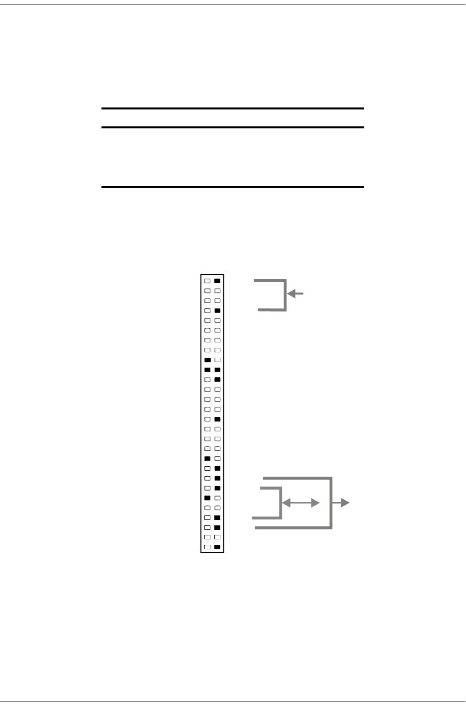
H2TU-R-402 LIST 4E CARD CONNECTOR
Figure 23 shows the card-edge connectors on the H2TU-R-402 List 4E. Active pins are highlighted in black.
Figure 23. H2TU-R-402 List 4E Card-Edge Connector
Table 13. HDSL2 Cable Attenuation Chart
Cable Gauge Loss at 196 kHz (dB/kft) Ω per kft
26/0.4 mm 3.88 83
24/0.51 mm 2.84 52
22/0.61 mm 2.18 32
19/0.91 mm 1.54 16
27
25
23
21
19
17
15
13
11
9
7
3
5
1
Tip
Ring
Factory use only
Factory use only
Factory use only
Ring1
CircuitGround
Ring
DS1IN
Tip
Tip1
ChassisGround*
ChassisGround*
28
26
24
22
20
18
16
14
12
10
8
4
6
2
55
53
51
49
47
45
43
41
39
37
35
32 31
56
54
52
50
48
46
44
42
40
38
36
34
30
33
29
Active pins are highlighted in black.
* Chassis Ground may be tied to Earth Ground according
to local practice.
HDSL2
Span
DS1OUT
−48V
Automaticprotectionswitchpower
Automaticprotectionswitchcontrol
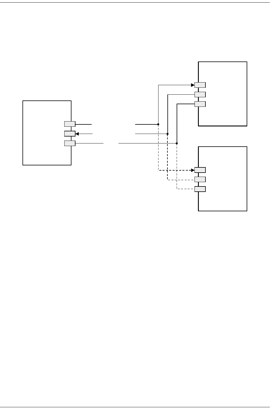
152-402-145-02, Issue 2 Appendix A - Specifications
H2TU-R-402 June 16, 2000 33
CRAFT PORT
Figure 24 shows the pinout for the craft port connector and its connection to a DB-9 or DB-25 connector on a
maintenance terminal.
Figure 24. RS-232 Craft Port Pinouts
H2TU-R-402
DB-9 Connector
(DCE)
RD (Receive Data)
TD (Transmit Data)
3
2
5
DB-9 Connector
(DTE)
DB-25 Connector
(DTE)
2
3
5
3
2
7
GND
Terminal
Terminal
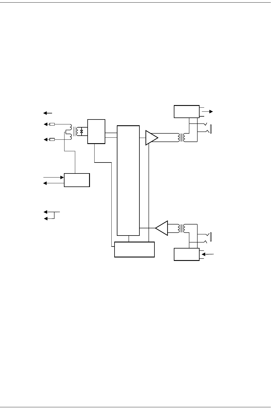
Appendix B - Functional Operation 152-402-145-02, Issue 2
34 June 16, 2000 H2TU-R-402
APPENDIX B - FUNCTIONAL OPERATION
ADC HDSL2 technology provides full-duplex services at standard DS1 rates over copper wires between an
H2TU-C and an H2TU-R, which comprise one HiGain HDSL2 system. HiGain HDSL2 systems use ADC
Overlapped PAM Transmission with Interlocking Spectra (OPTIS) transceiver systems to establish full-duplex,
1.552 kbps data channels between the remotely located H2TU-R-402 List 4E and an H2TU-C.
A block diagram of the H2TU-R-402 List 4E is shown in Figure 25.
The H2TU-R-402 List 4E power supply converts the 90 to 200 Vdc power that is received on the simplex pairs to
voltage and currents required by the remote unit circuitry.
Figure 25. H2TU-R-402 List 4E Block Diagram
TIMING
The low-loop wander (0.3 UI max) of an H2TU-R-402, when used with a compatible line unit, allows the circuit
to be used in all critical timing applications, including those that are used to transport Stratum 1 timing.
HDSL2
XCVR
Microprocessor
Protection
Protection
Factory use only
BRG
Tip
Ring
Tip1
Ring1
BRG OUT(RCV)
49
55
IN(XMT)
5
15
13
20
7
Ring
Tip
Framer
Loopback
CLOC
NREM
Circuit
Ground
17
Chassis Ground
1
+
Power
Supply
DS1 OUT
(RCV)
HDSL2
HDSL2 Span
DS1 IN
(XMT)
35 48V IN
27

152-402-145-02, Issue 2 Appendix C - Compatibility
H2TU-R-402 June 16, 2000 35
APPENDIX C - COMPATIBILITY
The HiGain HDSL2 system uses HDSL2 transmission technology as recommended by Bellcore TA-TSY-001210.
HiGain HDSL2 complies with GR-63-CORE, TR-TSY-000499, and GR-1089-CORE.
The H2TU-R-402 List 4E is compatible with the following shelves (for indoor use):
•HRE-204 (four-slot)
•HRE-420 (single-slot)
•HRE-425 (12-slot wall or rack mount)
•200 Mechanics type shelves
•400 Mechanics type shelves
For outdoor applications, the H2TU-R-402 List 4E is compatible with the following enclosures:
•HRE-450 List xB (single-slot)
•HRE-454 (four-slot)

Appendix D - Product Support 152-402-145-02, Issue 2
36 June 16, 2000 H2TU-R-402
APPENDIX D - PRODUCT SUPPORT
ADC Customer Service Group provides expert pre-sales and post-sales support and training for all its products.
Technical support is available 24 hours a day, 7 days a week by contacting the ADC Technical Assistance Center
(TAC).
Sales Assistance
800.366.3891 extension 73000
(USA and Canada)
952.917.3000
Fax: 952.917.3237
•Quotation Proposals
•Ordering and Delivery
•General Product Information
Systems Integration
800.366.3891, extension 73000
(USA and Canada)
952.917.3000
•Complete Solutions (from concept to
installation)
•Network Design and Integration Testing
•System Turn-Up and Testing
•Network Monitoring (upstream or downstream)
•Power Monitoring and Remote Surveillance
•Service/Maintenance Agreements
•Systems Operation
ADC Technical Assistance Center
800.638.0031
714.730.3222
Fax: 714.730.2400
Email: wsd_support@adc.com
•Technical Information
•System/Network Configuration
•Product Specification and Application
•Training (product-specific)
•Installation and Operation Assistance
•Troubleshooting and Repair/Field Assistance
Online Technical Support •www.adc.com/Knowledge_Base/index.jsp
Online Technical Publications •www.adc.com/library1/
Product Return Department
800.366.3891 ext. 73748 or
952.917.3748
Fax: 952.917.3237
Email: repair&return@adc.com
•ADC Return Material Authorization (RMA)
number and instructions must be obtained
before returning products.
All 800 lines are toll-free in the USA and Canada.

Appendix E - Abbreviations 152-402-145-02, Issue 2
37 June 16, 2000 H2TU-R-402
APPENDIX E - ABBREVIATIONS
A
ACO: Alarm Cutoff
ACON: Auto Conversion
ADSL: Asymmetrical Digital Subscriber Line
AIS: Alarm Indication Signal
AIS-CI: Alarm Indication Signal-Customer Installation
ALM: Alarm
ALMP: Alarm Pattern
ANSI: American National Standards Institute
AOR: Addressable Office Repeater
ARM: Armed
AUTO: Auto-Framing Mode
AWG: American Wire Gauge
B
BER: Bit Error Rate
BPV: Bipolar Violation
BPVT: Bipolar Violation Transparency
BRG: Bridge
C
CEV: Controlled Environmental Vault
CI: Customer Interface
CLEI: Common Language Equipment Identifier
CLOC: Customer Local Loopback
CO: Central Office
CONV: Conversion
CPE: Customer Premises Equipment
CRC: Cyclical Redundancy Check
CREM: Customer Remote Loopback
CSA: Carrier Service Area
CV: Code Violation
CV-P: Code Violation-Path
D
DBER: DS1 Bit Error Rate
DDS: Digital Data Service
DL: Datalink
DLC: Digital Loop Carrier
DSX-1: Digital Signal Cross-Connect, Level 1
E
ECI: Equipment Catalog Item
EQL: Equalization
ES: Errored Seconds
ESD: Electrostatic Discharge
ES-L: Errored Seconds-Line
ES-P: Errored Seconds-Path
EXZ: The occurrence of 8 consecutive zeroes for B8ZS or 16
for AMI.
F
FCON: Frame Conversion
FDL: Frame Bit for Datalink, Facility Datalink
FE: Far End
FPS: Framing Pattern Sequence
H
HCDS: High Capacity Digital Service
HCS: HiGain Card Shelf
HDSL: High-bit-rate Digital Subscriber Line
HDSL2: High-bit-rate Digital Subscriber Line 2
HG: HiGain
I
ID: Identification
ILR: Intelligent Line Repeater
IN: Transmit
IOR: Intelligent Office Repeater
IR: Intelligent Repeater
L
LA: Loop Attenuation
LAIS: Local Alarm Indication Signal
LBPV: Local Bipolar Violation
LED: Light Emitting Diode
LLOS: Local Loss of Signal
LOS: Loss of Signal
LOSW: Loss of Sync Word
LPDN: Loopdown
LPF: Line Power Feed
LRAI: Line RAI
M
MAL: Margin Alarm
MNGD: Managed
MSEC: Monitored Seconds
N
NE: Near End
NEBS: Network Equipment-Building System
NI: Network Interface
NID: Network Interface Device
NLOC: Network Local Loopback
NMA: Network Management and Administration
NPRM: Network PRM

152-402-145-02, Issue 2 Appendix E - Abbreviations
H2TU-R-402 June 16, 2000 38
NREM: Network Remote Loopback
NTF: No Trouble Found
O
OOF: Out-of-Frame
OPTIS: Overlapped Pulse Amplitude Modulation Transmission
with Interlocking Spectra
OUT: Receive
P
PBOC: Power Back Off Customer
PBON: Power Back Off Network
PL: Payload
POTS: Plain Old Telephone Service
PRM: Performance Report Messaging
PRM-FE: Performance Report Messaging-Far End
PRM-NE: Performance Report Messaging-Near End
PWRF: Power Feed
R
RAI: Remote Alarm Indication
RAI-CI: Remote Alarm Indication-Customer Installation
RAIS: Remote Alarm Indication Signal
RDA: Remote Disconnect Alarm
RLOS: Remote Loss of Signal
RMA: Return Material Authorization
ROVR: RAI Overwrite
RRAI: Remote RAI
S
SDSL: Symmetrical Digital Subscriber Line
SES: Severely Errored Seconds
SES-L: Severely Errored Seconds-Line
SES-P: Severely Errored Seconds-Path
SF: SuperFrame
SMJK: SmartJack
SNET: Southern New England Telephone
SPLB: Special Loopback
SPRM: Supplemental PRM
T
TLOS: Transmit Loss of Signal
U
UAS: Unavailable Seconds
UAS-P: Unavailable Seconds-Path
UNFR: Unframed
X
XMT: transmit

CERTIFICATION AND WARRANTY
FCC CLASS A COMPLIANCE
This equipment has been tested and found to comply with the limits for a Class A digital device, pursuant to Part 15 of the FCC Rules. These
limits are designed to provide reasonable protection against harmful interference when the equipment is operated in a commercial
environment. This equipment generates, uses, and can radiate radio frequency energy and, if not installed and used in accordance with the
instruction manual, may cause harmful interference to radio communications. Operation of this equipment in a residential area is likely to
cause harmful interference in which case the user will be required to correct the interference at his own expense.
LIMITED WARRANTY
ADC DSL Systems, Incorporated (“ADC”) warrants that, for a period of sixty (60) months from the date of shipment, the hardware portion
of its products will be free of material defects and faulty workmanship under normal use. ADC's obligation, under this warranty, is limited to
replacing or repairing, at ADC's option, any such hardware product which is returned during the 60-month warranty period per ADC's
instructions and which product is confirmed by ADC not to comply with the foregoing warranty.
ADC warrants that, for a period of 90 days from the date of purchase, the software furnished with its products will operate substantially in
accordance with the ADC published specifications and documentation for such software. ADC’s entire liability for software that does not
comply with the foregoing warranty and is reported to ADC during the 90-day warranty period is, at ADC’s option, either (a) return of the
price paid or (b) repair or replace of the software. ADC also warrants that, for a period of thirty (30) days from the date of purchase, the media
on which software is stored will be free from material defects under normal use. ADC will replace defective media at no charge if it is returned
to ADC during the 30-day warranty period along with proof of the date of shipment.
The transportation charges for shipment of returned products to ADC will be prepaid by the Buyer. ADC will pay transportation charges for
shipment of replacement products to Buyer, unless no trouble is found (NTF), in which case the Buyer will pay transportation charges.
ADC may use reconditioned parts for such repair or replacement. This warranty does not apply to any product which has been repaired, worked
upon, or altered by persons not authorized by ADC or in ADC's sole judgment has been subjected to misuse, accident, fire or other casualty,
or operation beyond its design range.
Repaired products have a 90-day warranty, or until the end of the original warranty period—whichever period is greater.
ADC DISCLAIMS ALL OTHER WARRANTIES, EITHER EXPRESS OR IMPLIED, INCLUDING BUT NOT LIMITED TO IMPLIED
WARRANTIES OF MERCHANTABILITY AND FITNESS FOR A PARTICULAR PURPOSE, WITH RESPECT TO ITS PRODUCTS
AND ANY ACCOMPANYING WRITTEN MATERIALS. FURTHER, ADC DOES NOT WARRANT THAT SOFTWARE WILL BE
FREE FROM BUGS OR THAT ITS USE WILL BE UNINTERRUPTED OR REGARDING THE USE, OR THE RESULTS OF THE USE,
OF THE SOFTWARE IN TERMS OF CORRECTNESS, ACCURACY, RELIABILITY OR OTHERWISE.
MODIFICATIONS
Any changes or modifications made to this device that are not expressly approved by ADC DSL Systems, Inc. voids the user's warranty.
All wiring external to the products should follow the provisions of the current edition of the National Electrical Code.
SAFETY STANDARDS COMPLIANCE
The H2TU-R-402 List 4E modules have been tested and verified to comply with the applicable sections of the following safety standards:
•GR 63-CORE - Network Equipment-Building System (NEBS) Requirements
•GR 1089-CORE - Electromagnetic Compatibility and Electrical Safety
•UL-1459, 3rd Edition and CSA C22.2 225-M90: Telecommunications Equipment – Electronics and Electrical Safety
For technical assistance, refer to “Appendix D - Product Support” on page 36.

ADC DSL Systems, Inc.
14402 Franklin Avenue
Tustin, CA 92780-7013
Tel: 714.832.9922
Fax: 714.832.9924
Technical Assistance
Tel: 800.638.0031
Tel: 714.730.3222
Fax: 714.730.2400
DNV C ertificatio n, Inc.
REGISTERED FIRM
ISO 9001/TL 9000 DOCUMENT: 152-402-145-02, ISSUE 2
´+z.¶9G¨
1214394
