Ademco 7720PLUS LIcensed fixed location security transmitter User Manual Draft of Installation Instructions
Honeywell International Inc. LIcensed fixed location security transmitter Draft of Installation Instructions
Ademco >
Contents
- 1. Draft of Installation Instructions
- 2. Users Manual Rev C
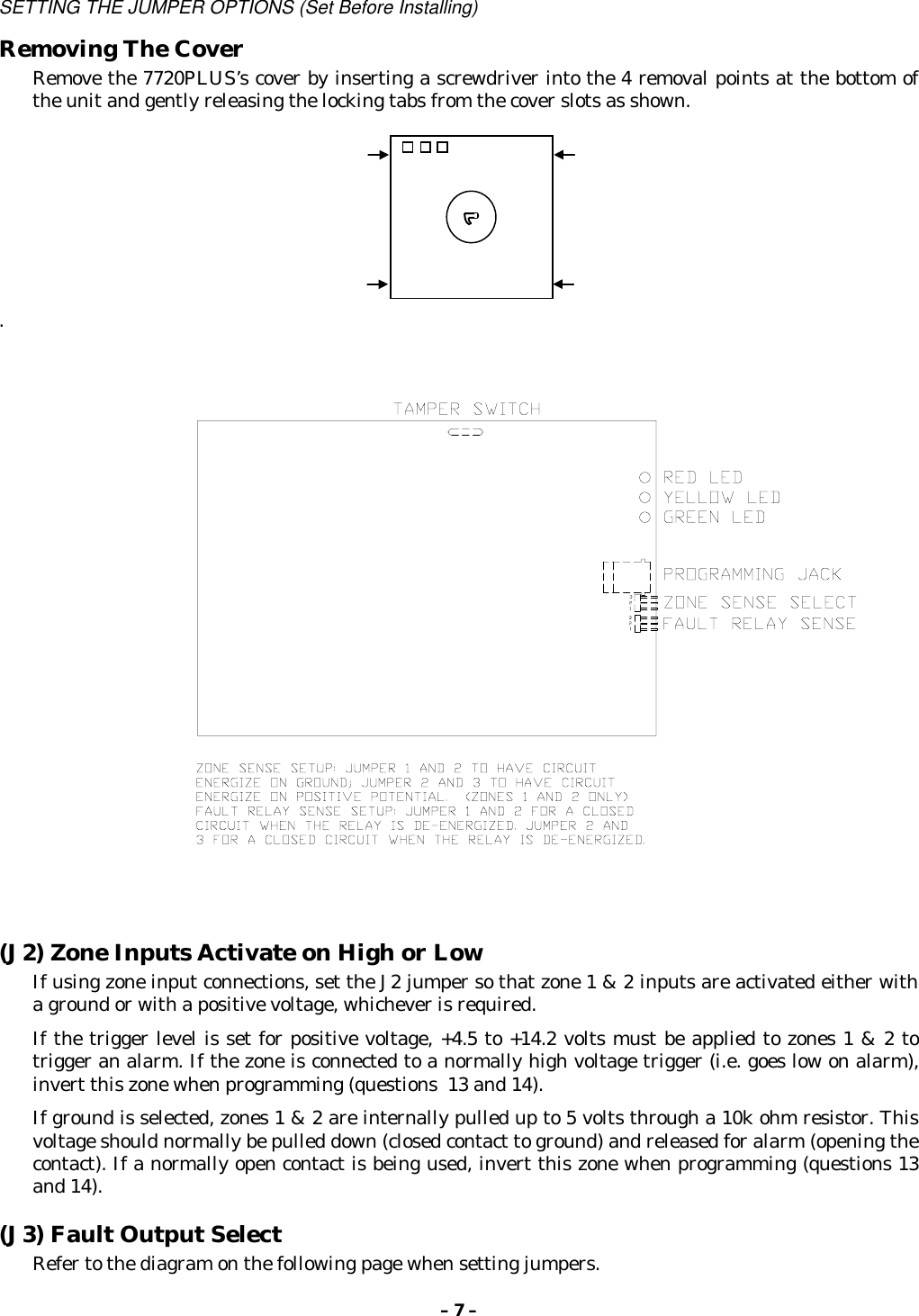
Draft of Installation Instructions

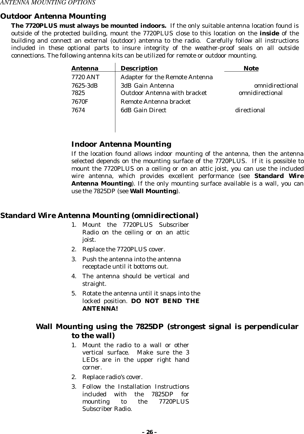
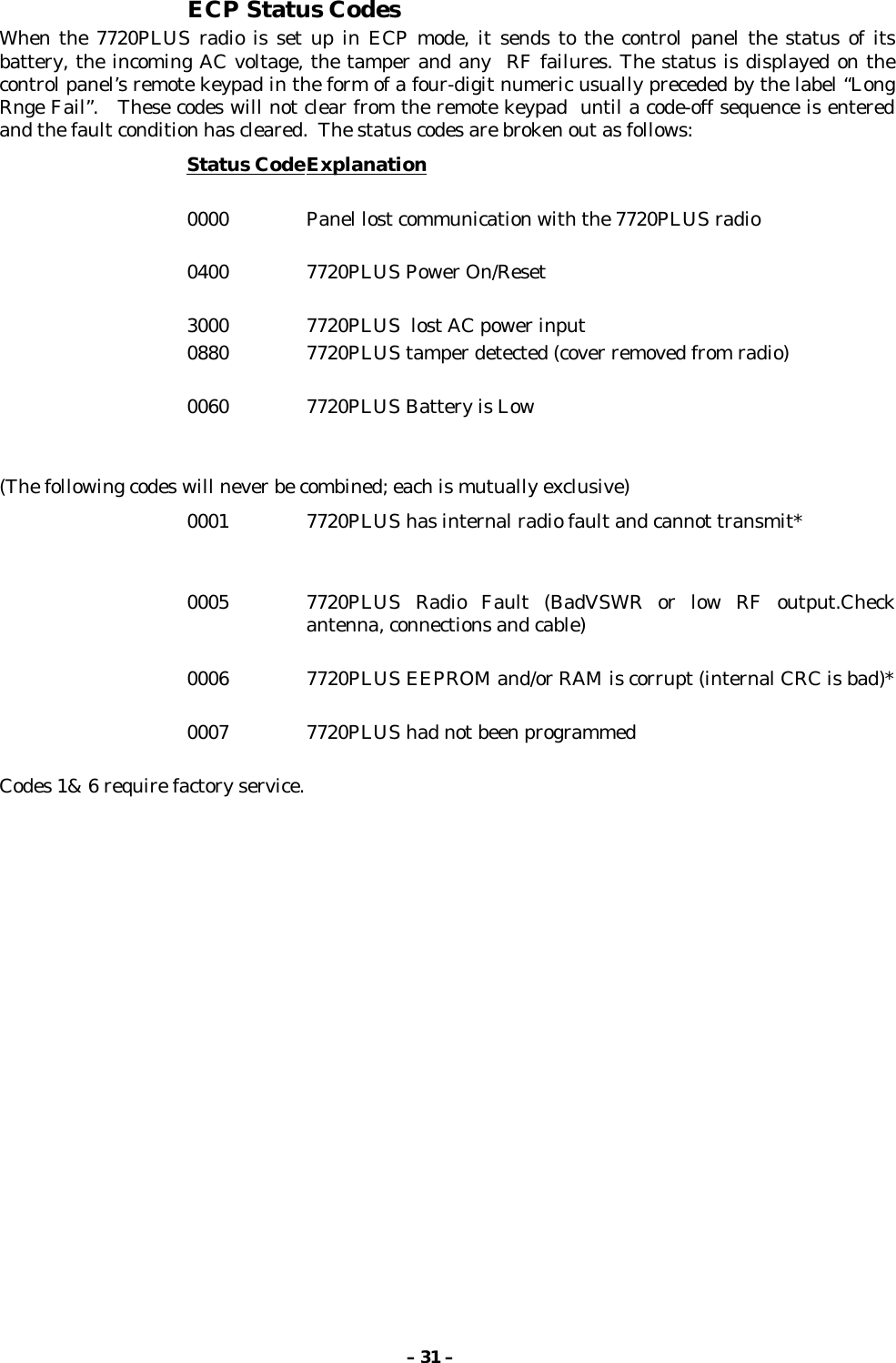
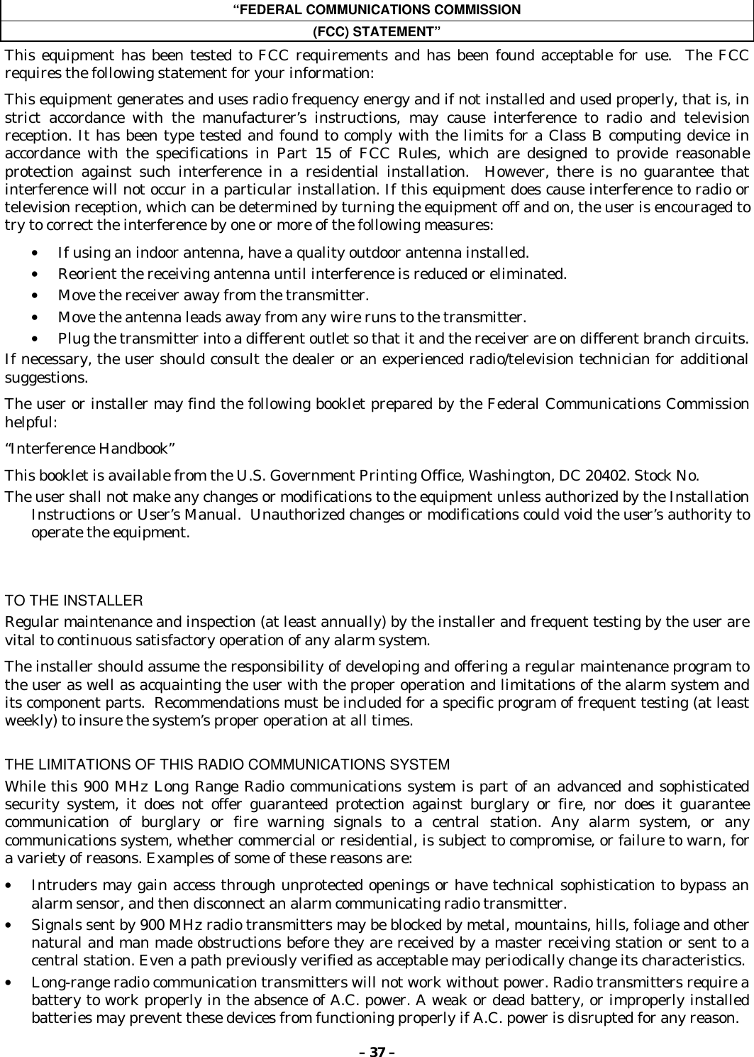
![– 5 –the fault output is explained later in this chapter). If no messages are received during the supervisorywindow, the network will generate a communication failure signal to the central station.Available in zone mode only is a contact closure used to locally indicate a radio fault. This can beeither normally open or normally closed. In addition it can be selected to be “fail-safe” byprogramming the fault output to be inverted (i.e. the relay is powered unless there is a fault). Thefault output is between TB1-11 and TB1-12, which float with reference to the rest of the circuit.Also available in zone mode only is the ability for the 7720PLUS to provide status information via itsserial port, thus allowing radio status to be displayed on command, using either a 7720PProgramming Tool or a computer terminal. Refer to the TESTING THE 7720PLUS section forinformation regarding the “S” command and status messages.LED IndicationsLED State MeaningGREEN Flash With YELLOW solid = Message transmissionYELLOW SolidRapid Flash(10 per second)Slow Flash(1/second)Slower Flash(1 per 3 seconds)Transmission cycle ONTest or FAST messageNormal operationNormal, but low battery condition detected.RED Solid Pattern Radio Fault detected. See flash patterns table below.YELLOWand RED Flashing in unison Loss of communications between the radio and thecontrol panel. (ECP mode only)AllilluminatedConsecutiveSlow Unison(2 per second)Power On/Reset sequence. Repeated twice beforeentering normal mode. Press [ENTER] during cycle toenter Program Mode.Radio is not properly programmed. Will continue until[ENTER] is pressed to enter programming mode. (IF inECP mode, radio must be rebooted before entering programmode)](https://usermanual.wiki/Ademco/7720PLUS.Draft-of-Installation-Instructions/User-Guide-81207-Page-5.png)


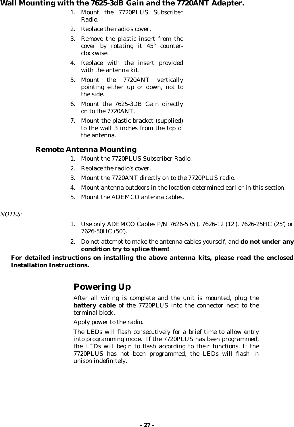
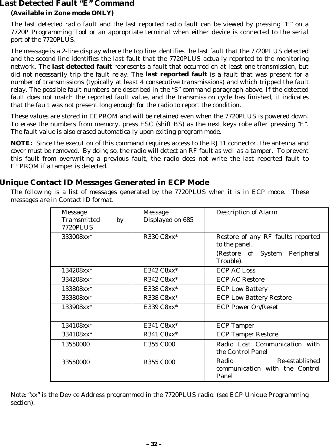
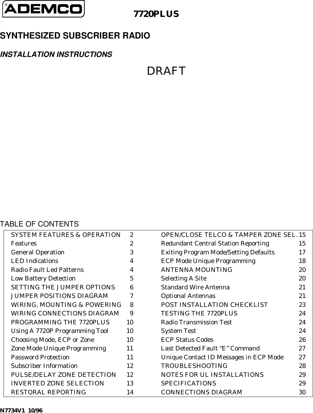
![– 12 –PROGRAMMING THE 7720PLUSUsing A 7720P Programming ToolThe 7720P Programming Tool is powered by the 7720PLUS, and connects to the telephone connectoron the 7720PLUS PC Board. Please note the the 7720P is not functional when the radio is running inECP mode; it is functional only during power-up of an ECP radio.IMPORTANT NOTE: Some of the older 7720P tools (those shipped prior to mid-1998) willnot function if the line voltage is too low. These can be modified using instructionssupplied on request, or they may be returned to Ademco for factory modification. All 7720P tools currently shipping will work without difficulty.Each key of the 7720P has two possible functions, a normal function and a SHIFT function. Toperform a normal key function, simply press the desired key. To perform a SHIFT key function, pressSHIFT key, then press desired function key.7720P Normal & Shift Key (shift LED lit) Functions Key Normal Key Function SHIFT Key FunctionBS/ESC [BS]: Press to delete entry [ESC]: Press to quit program mode.Also, can reset EEPROM defaults*↓ / ↑ [↓]: Scroll down programming [↑]: Scroll up programmingN/Y [N]: Press for “NO” answer. [Y]: Press SHIFT-Y for “YES”answerSHIFT Press before pressing a SHIFT key function. Will light SHIFT LED.LED goes out once a key is pressed. Press again for each SHIFT functiondesired.1/A [1]: For entering the number 1 [A]: Used for entering C.S. IDnumber2/B [2]: For entering the number 2 [B]: Used for entering C.S. IDnumber3/C [3]: For entering the number 3 [C]: Used for entering C.S. IDnumber4/D [4]: For entering the number 4 [D]: Used for entering C.S. IDnumber5/E [5]: For entering the number 5 [E]: Used for entering C.S. IDnumber6/F [6]: For entering the number 6 [F]: Used for C.S. ID & FAST mode7/S [7]: For entering the number 7 [S]: Press to display diagnosticstatus8/T [8]: For entering the number 8 [T]: Press to send TEST messages9/X [9]: For entering the number 9 [X]: Press to reset the 7720PLUS(Zone mode only) ✱/SPACE [✱]: Not used with 7720PLUS [SPACE]: Not used with 7720PLUS0 [0]: For entering the number 0 No SHIFT function #/ENTER [#/ENTER]: Press to accept entries No SHIFT function• Active only when the “REVIEW?” prompt is displayed.CHOOSING MODE: ECP OR ZONEUsing the 7720P, the user can enter the configuration set-up by pressing the enter key while theindividual LEDs rapidly flash sequentially. This will cause the radio to display the following prompton the 7720P display:ECP Radio[Y/N]](https://usermanual.wiki/Ademco/7720PLUS.Draft-of-Installation-Instructions/User-Guide-81207-Page-12.png)
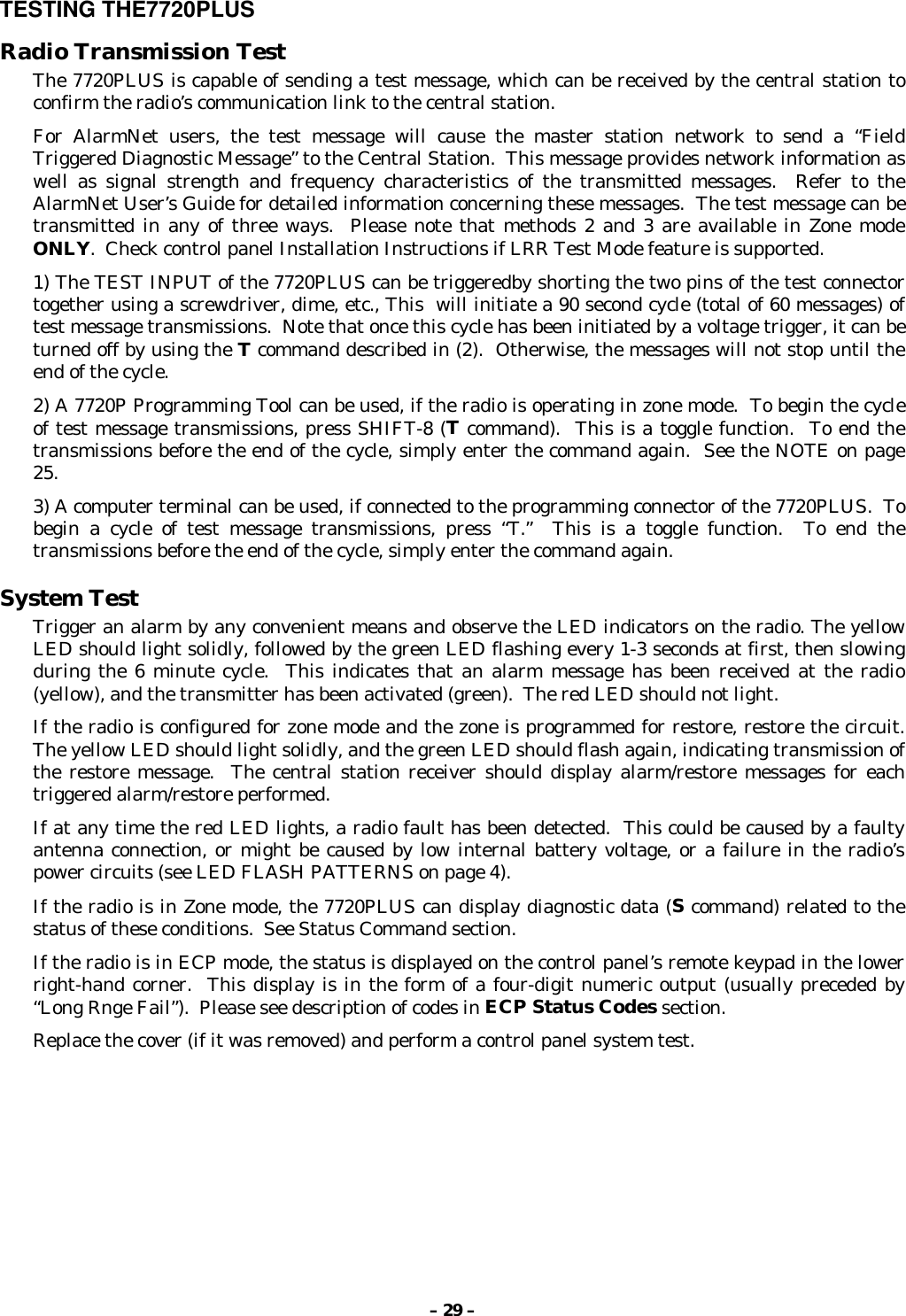
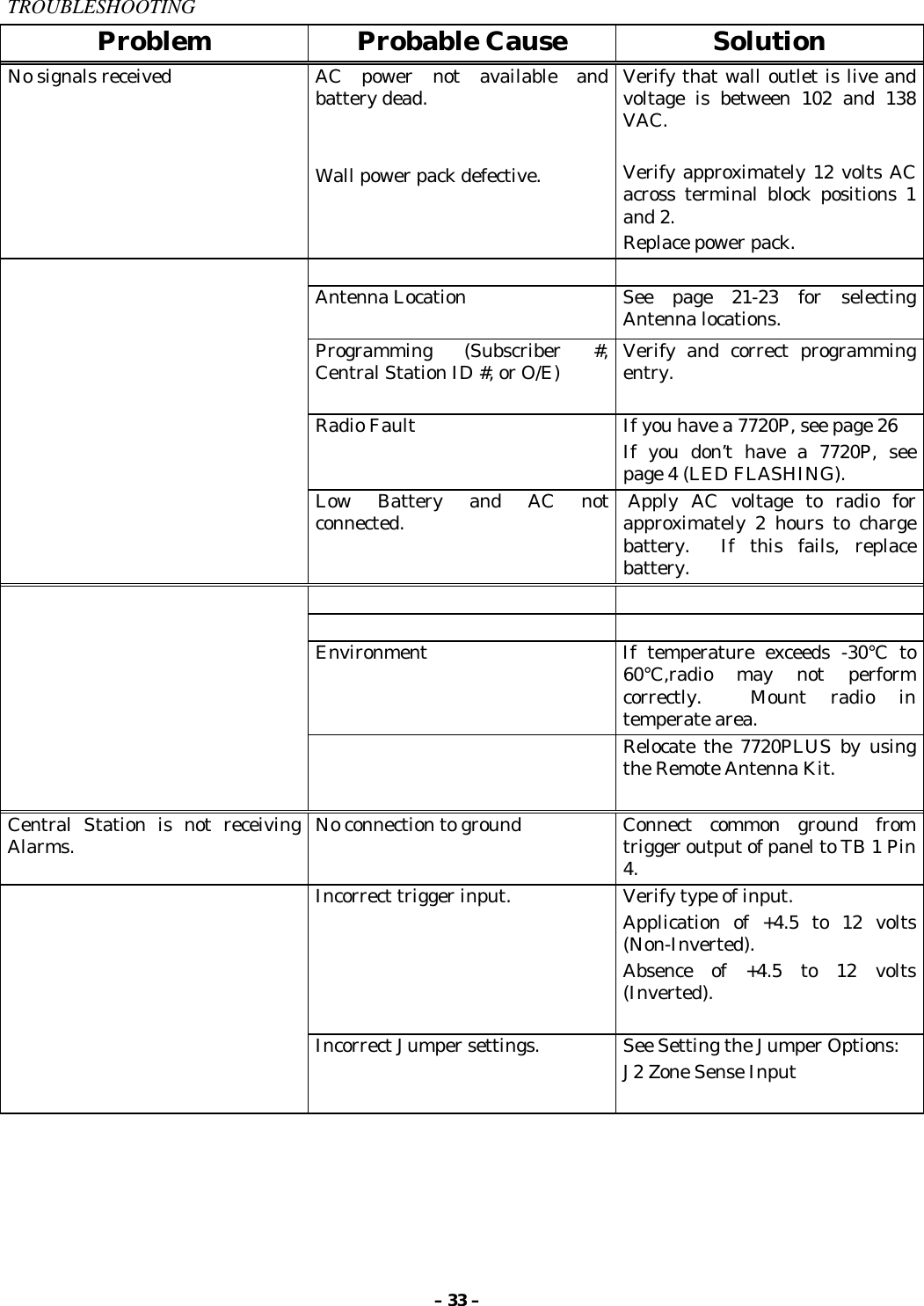
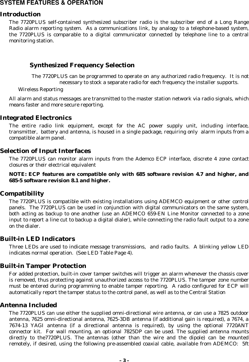
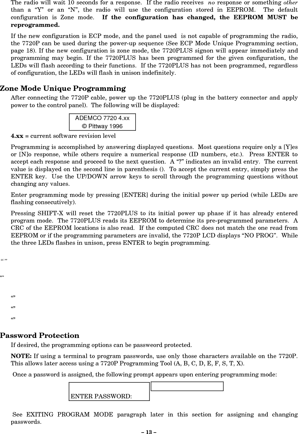
![– 13 –The radio will wait 10 seconds for a response. If the radio receives no response or something otherthan a “Y” or an “N”, the radio will use the configuration stored in EEPROM. The defaultconfiguration is Zone mode. If the configuration has changed, the EEPROM MUST bereprogrammed.If the new configuration is ECP mode, and the panel used is not capable of programming the radio,the 7720P can be used during the power-up sequence (See ECP Mode Unique Programming section,page 18). If the new configuration is zone mode, the 7720PLUS signon will appear immediately andprogramming may begin. If the 7720PLUS has been programmed for the given configuration, theLEDs will flash according to their functions. If the 7720PLUS has not been programmed, regardlessof configuration, the LEDs will flash in unison indefinitely.Zone Mode Unique ProgrammingAfter connecting the 7720P cable, power up the 7720PLUS (plug in the battery connector and applypower to the control panel). The following will be displayed:ADEMCO 7720 4.xx© Pittway 19964.xx = current software revision levelProgramming is accomplished by answering displayed questions. Most questions require only a [Y]esor [N]o response, while others require a numerical response (ID numbers, etc.). Press ENTER toaccept each response and proceed to the next question. A “?” indicates an invalid entry. The currentvalue is displayed on the second line in parenthesis (). To accept the current entry, simply press theENTER key. Use the UP/DOWN arrow keys to scroll through the programming questions withoutchanging any values.Enter programming mode by pressing [ENTER] during the initial power up period (while LEDs areflashing consecutively).Pressing SHIFT-X will reset the 7720PLUS to its initial power up phase if it has already enteredprogram mode. The 7720PLUS reads its EEPROM to determine its pre-programmed parameters. ACRC of the EEPROM locations is also read. If the computed CRC does not match the one read fromEEPROM or if the programming parameters are invalid, the 7720P LCD displays “NO PROG”. Whilethe three LEDs flashes in unison, press ENTER to begin programming.“”“”“”“”“”Password ProtectionIf desired, the programming options can be passweord protected.NOTE: If using a terminal to program passwords, use only those characters available on the 7720P.This allows later access using a 7720P Programming Tool (A, B, C, D, E, F, S, T, X). Once a password is assigned, the following prompt appears upon entering programming mode:ENTER PASSWORD: See EXITING PROGRAM MODE paragraph later in this section for assigning and changingpasswords.](https://usermanual.wiki/Ademco/7720PLUS.Draft-of-Installation-Instructions/User-Guide-81207-Page-13.png)


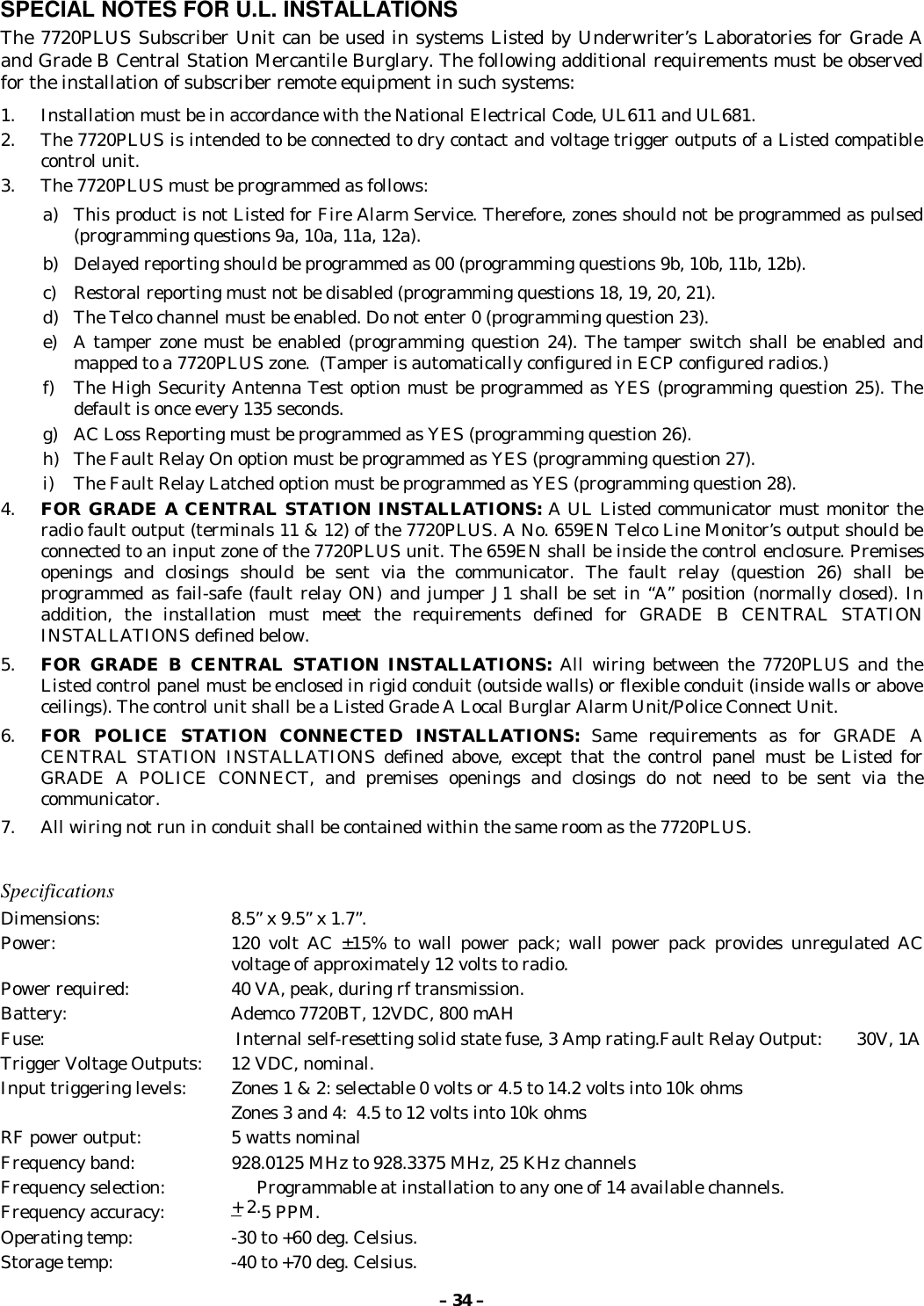
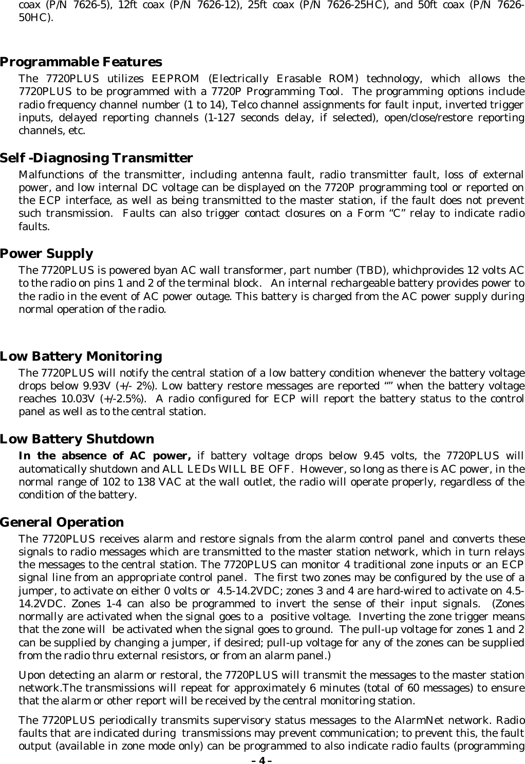
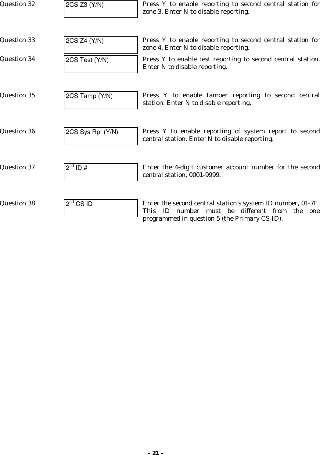
![– 20 –OPEN/CLOSE, TELCO & TAMPER ZONE SELECTIONQuestion 22 O/C Zone Enter the open/close reporting zone number, 1-4. A [0] entrydisables open/close reporting. If the zone selected was programmedto be a pulse zone, (see Questions 8-11), this zone number selectionis invalid and will be tagged as an error.Question 23 Telco Chan Enter the physical Telco line fault zone, 1-4. A [0] entry disablesTelco detection. If this zone is the same as the open/close zone,this selection will automatically be set to “0” and Telcodetection will be disabled. If the zone selected was programmedto a pulse zone (see Questions 8-11) this zone number selection isinvalid and will be tagged as an error.Question 24 Tamper zone Enter tamper zone, 5-8. A [0] entry disables tamper detection. Iftamper is enabled, delayed restores will be automaticallygenerated.Question 25.HS Ant. Tst (Y/N) Press Y for 135 second interval antenna test. Press N if no antennatest is desired.Question 26.AC Loss RPT (Y/N) If AC LOSS RPT is answered yes (Y), the radio will report the lossof AC voltage within a 10 to 40 minute window, from its detection.If this feature is disabled (N), this message will be suppressed.NOTE: In either case, low battery messages will be sent asdetected.Question 27 FLT REL ON (Y/N) Press Y if fail-safe mode is desired. In this mode, the fault relay isnormally energized and will de-energize in the event of a radiofault. Note that fail-safe mode draws slightly more standbycurrent. See the SETTING THE JUMPERS section for setting therelay output.Question 28 Flt Latched(Y/N) Press Y if radio fault line is to be latched high upon detection oftransmission error. Press N if a momentary closure upon detectionof transmission error is desired.REDUNDANT CENTRAL STATION REPORTINGQuestion 29 2nd CS (Y/N) Press Y if redundant reporting to a second central station isdesired. Press N if not desired (skip to end).Question 30 2CS Z1 (Y/N) Press Y to enable reporting to second central station forzone 1. Enter N to disable reporting.Question 31 2CS Z2 (Y/N) Press Y to enable reporting to second central station forzone 2. Enter N to disable reporting.](https://usermanual.wiki/Ademco/7720PLUS.Draft-of-Installation-Instructions/User-Guide-81207-Page-20.png)
![– 22 –EXITING PROGRAM MODE, SETTING DEFAULTS & ASSIGNING PASSWORDSWhen the last question is answered, all entries are validated by the system. If no errors are found, thefollowing is displayed:REVIEW?To review the programming options (to ensure that the correct responses have been made), press Y.The programming questions will be displayed again, starting with question 1. Use the UP/DOWN arrowkeys to scroll through the program fields without changing any of the values. If a value requires change,simply type in the correct value. When the last field is displayed, the REVIEW? question again appears.If errors are found during the validation routine (values are out of range or there is a conflict ofparameters), the REVIEW? question is replaced by the following:ERRORS FOUNDHIT ANY KEYUpon hitting any key, the first invalid entry is displayed.Correct the entry then press ENTER to display the nextinvalid entry. When the last invalid entry is corrected, thesystem again performs a validation routine. If no errors arefound, the REVIEW? question is displayed.To display all program entries (not only invalid entries)press the up arrow key. The previous question appears. Usethe down arrow key to display subsequent programmingentries.Setting Factory Defaults: The programming options can be globally reset to their factory defaultvalues by pressing ESC at the REVIEW? prompt. A confirmation prompt will appear. Press Y to reset,or press N to return to the REVIEW? prompt. If Y is pressed, all programmed values will be reset totheir original factory settings.To exit program mode & assign passwords, press N in response to the REVIEW? question. If nopassword has been assigned, the following appears:ENTER PASSWORD?[Y/N]Passwords can be used to split the programming questions intotwo menus. See PASSWORD PROTECTION paragraph earlierin this section. If a password is desired, press Y. The followingprompts appear. Press N if no passwords are desired.ENTER PASSWORD: Enter the desired password (up to 4 digits max).Verify Password Re-enter the password for confirmation.NOTE: If using a terminal to program passwords, use only those characters available on the 7720P, toallow later access using a 7720P (A, B, C, D, E, F, S, T, X).](https://usermanual.wiki/Ademco/7720PLUS.Draft-of-Installation-Instructions/User-Guide-81207-Page-22.png)
![– 23 –If a password has already been assigned for the current programming menu, the ENTERPASSWORD? prompt is replaced by the following:CHG PASSWORD?[Y/N]Press Y or N, depending on whether you want to change thepassword for the current programming menu. If [Y]es, youwill be prompted to enter the new password twice (asconfirmation). To clear an existing password, answer “Y” tothe “change password” prompt, but press only the ENTERkey when prompted for the new password and itsconfirmation.When the password question(s) have been answered, the system exits program mode and returns tonormal mode. The Programming Tool can then be disconnected, or can be used to trigger testmessages. Refer to the TESTING THE 7720PLUS section. NOTE: Older programming tools {shipped prior to mid-1998 and not modified) cannot be used to send atest message; they will cause a reset condition. Use the test message posts on the radio to send a testmessage without using the 7720P.ECP MODE UNIQUE PROGRAMMINGIf ECP mode has been selected and the control panel being used does not support programming mode(e.g. VIA30+), the 7720P can be used to program the radio. To enter programming mode, the<ENTER> key of the 7720P must be pressed during the sequential flashing of the LEDs. Thefollowing sign-on message will be displayed for one second:7720ECP xxx(c)Pittway 1999 xxx = current software revision levelAll displayed questions must be answered. The subsequent question will not be displayed until thecurrent question is answered. Unlike the case of the Zone mode, pressing <ESC> will not bring thelist of programming questions to the end, if any question has been left unanswered.Question 1 Device Addr Enter the Device Address of the radio. For VIA 30+, VISTA 10 andVISTA 20 families, this must be 3. For other control panels, see thepanel’s installation instructions.Question 2 ID# Enter the 4-digit customer account number, 0001-9999.This account number will appear in the messages generated by theradio. Messages generated by the panel will contain the subscriber IDnumber programmed in the panel.Question 3 Odd (Y/N) Enter Y for Odd flag (bit value 1), N for even system flag (bit value 0).Question 4 15 MIN SUPV (Y/N) Status reporting is always enabled. Enter the desired interval asfollows:Y = Short form: every 15 minutes (6-hour window for COM-FAILreport)N = Short form: every hour (standard 24 hour reporting for COM-FAIL)](https://usermanual.wiki/Ademco/7720PLUS.Draft-of-Installation-Instructions/User-Guide-81207-Page-23.png)
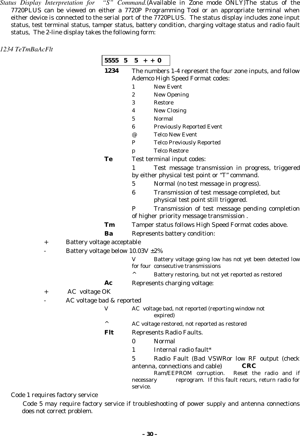
![– 25 –ANTENNA MOUNTINGSelecting A LocationIf Non UL installation, an antenna location which has reliable communications with at least onebase station with an uplink signal strength reading of “3” or greater may be used .NOTE: Place a check mark [✔✔] in the “Single Site Supervision” box on the SubscriberContract.For UL Grade “A” or Grade “B” installations, find an antenna location which has reliablecommunication to at least two AlarmNet Base Stations with a minimum uplink signal strengthreading of “3”.After determining the type of installation required (UL, Non UL) find an antenna locationwithin the premises. Locations can be found by utilizing the test mode of the 7720PLUS (seeTESTING THE 7720PLUS section), the 7715 FAST Tool or the 7920 series transceiver.Notes On AntennaMounting 1. Optimum RF performance can usually be found at the highestpoint within a building, with the fewest number of wallsbetween the radio and the outside of the premises.2. Avoid mounting the antenna near other electronic devices. The followingtable provides minimum distances. Highest RF energy is in the direct,horizontal line of the antenna. Therefore, vertical separation (movingelectronic devices either higher or lower on wall) provides a higher level ofisolation from the radio.Equipment DistanceShort range receiver 20 ft.PIR 10 ft.Control panel 25 ft.FM radio or TV ant. 25 ft.other devices 10 ft. minimumThe diagram below displays the 7720PLUS mounting options and theappropriate antenna hardware to be used in each of these situations.](https://usermanual.wiki/Ademco/7720PLUS.Draft-of-Installation-Instructions/User-Guide-81207-Page-25.png)