Ademco 7720PLUS LIcensed fixed location security transmitter User Manual Draft of Installation Instructions
Honeywell International Inc. LIcensed fixed location security transmitter Draft of Installation Instructions
Ademco >
Contents
- 1. Draft of Installation Instructions
- 2. Users Manual Rev C
Draft of Installation Instructions

N7734V1 10/96
7720PLUS
SYNTHESIZED SUBSCRIBER RADIO
INSTALLATION INSTRUCTIONS
DRAFT
TABLE OF CONTENTS
SYSTEM FEATURES & OPERATION 2 OPEN/CLOSE TELCO & TAMPER ZONE SEL.15
Features 2 Redundant Central Station Reporting 15
General Operation 3 Exiting Program Mode/Setting Defaults 17
LED Indications 4 ECP Mode Unique Programming 18
Radio Fault Led Patterns 4 ANTENNA MOUNTING 20
Low Battery Detection 5 Selecting A Site 20
SETTING THE JUMPER OPTIONS 6 Standard Wire Antenna 21
JUMPER POSITIONS DIAGRAM 7 Optional Antennas 21
WIRING, MOUNTING & POWERING 8 POST INSTALLATION CHECKLIST 23
WIRING CONNECTIONS DIAGRAM 9 TESTING THE 7720PLUS 24
PROGRAMMING THE 7720PLUS 10 Radio Transmission Test 24
Using A 7720P Programming Tool 10 System Test 24
Choosing Mode, ECP or Zone 10 ECP Status Codes 26
Zone Mode Unique Programming 11 Last Detected Fault “E” Command 27
Password Protection 11 Unique Contact ID Messages in ECP Mode 27
Subscriber Information 12 TROUBLESHOOTING 28
PULSE/DELAY ZONE DETECTION 12 NOTES FOR UL INSTALLATIONS 29
INVERTED ZONE SELECTION 13 SPECIFICATIONS 29
RESTORAL REPORTING 14 CONNECTIONS DIAGRAM 30

N7734V1 10/96
Note to the Installer: Please read these Installation Instructions all the way through and become
completely familiar with them before attempting to install a 7720PLUS subscriber radio. Note to pubs:
change p/n and rev date

– 3 –
SYSTEM FEATURES & OPERATION
Introduction
The 7720PLUS self-contained synthesized subscriber radio is the subscriber end of a Long Range
Radio alarm reporting system. As a communications link, by analogy to a telephone-based system,
the 7720PLUS is comparable to a digital communicator connected by telephone line to a central
monitoring station.
Synthesized Frequency Selection
The 7720PLUS can be programmed to operate on any authorized radio frequency. It is not
necessary to stock a separate radio for each frequency the installer supports.
Wireless Reporting
All alarm and status messages are transmitted to the master station network via radio signals, which
means faster and more secure reporting.
Integrated Electronics
The entire radio link equipment, except for the AC power supply unit, including interface,
transmitter, battery and antenna, is housed in a single package, requiring only alarm inputs from a
compatible alarm panel.
Selection of Input Interfaces
The 7720PLUS can monitor alarm inputs from the Ademco ECP interface, discrete 4 zone contact
closures or their electrical equivalent
NOTE: ECP features are compatible only with 685 software revision 4.7 and higher, and
685-5 software revision 8.1 and higher.
Compatibility
The 7720PLUS is compatible with existing installations using ADEMCO equipment or other control
panels. The 7720PLUS can be used in conjunction with digital communicators on the same system,
both acting as backup to one another (use an ADEMCO 659-EN Line Monitor connected to a zone
input to report a line cut to backup a digital dialer), while connecting the radio fault output to a zone
on the dialer.
Built-in LED Indicators
Three LEDs are used to indicate message transmissions, and radio faults. A blinking yellow LED
indicates normal operation. (See LED Table Page 4).
Built-in Tamper Protection
For added protection, built-in cover tamper switches will trigger an alarm whenever the chassis cover
is removed, thus protecting against unauthorized access to the 7720PLUS. The tamper zone number
must be entered during programming to enable tamper reporting. A radio configured for ECP will
automatically report the tamper status to the control panel, as well as to the Central Station
Antenna Included
The 7720PLUS can use either the supplied omni-directional wire antenna, or can use a 7825 outdoor
antenna, 7625 omni-directional antenna, 7625-3DB antenna (if additional gain is required), a 7674, a
7674-13 YAGI antenna (if a directional antenna is required), by using the optional 7720ANT
connector kit. For wall mounting, an optional 7825DP can be used. The supplied antenna mounts
directly to the7720PLUS. The antennas (other than the wire and the dipole) can be mounted
remotely, if desired, using the following pre-assembled coaxial cable, available from ADEMCO: 5ft

– 4 –
coax (P/N 7626-5), 12ft coax (P/N 7626-12), 25ft coax (P/N 7626-25HC), and 50ft coax (P/N 7626-
50HC).
Programmable Features
The 7720PLUS utilizes EEPROM (Electrically Erasable ROM) technology, which allows the
7720PLUS to be programmed with a 7720P Programming Tool. The programming options include
radio frequency channel number (1 to 14), Telco channel assignments for fault input, inverted trigger
inputs, delayed reporting channels (1-127 seconds delay, if selected), open/close/restore reporting
channels, etc.
Self -Diagnosing Transmitter
Malfunctions of the transmitter, including antenna fault, radio transmitter fault, loss of external
power, and low internal DC voltage can be displayed on the 7720P programming tool or reported on
the ECP interface, as well as being transmitted to the master station, if the fault does not prevent
such transmission. Faults can also trigger contact closures on a Form “C” relay to indicate radio
faults.
Power Supply
The 7720PLUS is powered byan AC wall transformer, part number (TBD), whichprovides 12 volts AC
to the radio on pins 1 and 2 of the terminal block. An internal rechargeable battery provides power to
the radio in the event of AC power outage. This battery is charged from the AC power supply during
normal operation of the radio.
Low Battery Monitoring
The 7720PLUS will notify the central station of a low battery condition whenever the battery voltage
drops below 9.93V (+/- 2%). Low battery restore messages are reported “” when the battery voltage
reaches 10.03V (+/-2.5%). A radio configured for ECP will report the battery status to the control
panel as well as to the central station.
Low Battery Shutdown
In the absence of AC power, if battery voltage drops below 9.45 volts, the 7720PLUS will
automatically shutdown and ALL LEDs WILL BE OFF. However, so long as there is AC power, in the
normal range of 102 to 138 VAC at the wall outlet, the radio will operate properly, regardless of the
condition of the battery.
General Operation
The 7720PLUS receives alarm and restore signals from the alarm control panel and converts these
signals to radio messages which are transmitted to the master station network, which in turn relays
the messages to the central station. The 7720PLUS can monitor 4 traditional zone inputs or an ECP
signal line from an appropriate control panel. The first two zones may be configured by the use of a
jumper, to activate on either 0 volts or 4.5-14.2VDC; zones 3 and 4 are hard-wired to activate on 4.5-
14.2VDC. Zones 1-4 can also be programmed to invert the sense of their input signals. (Zones
normally are activated when the signal goes to a positive voltage. Inverting the zone trigger means
that the zone will be activated when the signal goes to ground. The pull-up voltage for zones 1 and 2
can be supplied by changing a jumper, if desired; pull-up voltage for any of the zones can be supplied
from the radio thru external resistors, or from an alarm panel.)
Upon detecting an alarm or restoral, the 7720PLUS will transmit the messages to the master station
network.The transmissions will repeat for approximately 6 minutes (total of 60 messages) to ensure
that the alarm or other report will be received by the central monitoring station.
The 7720PLUS periodically transmits supervisory status messages to the AlarmNet network. Radio
faults that are indicated during transmissions may prevent communication; to prevent this, the fault
output (available in zone mode only) can be programmed to also indicate radio faults (programming

– 5 –
the fault output is explained later in this chapter). If no messages are received during the supervisory
window, the network will generate a communication failure signal to the central station.
Available in zone mode only is a contact closure used to locally indicate a radio fault. This can be
either normally open or normally closed. In addition it can be selected to be “fail-safe” by
programming the fault output to be inverted (i.e. the relay is powered unless there is a fault). The
fault output is between TB1-11 and TB1-12, which float with reference to the rest of the circuit.
Also available in zone mode only is the ability for the 7720PLUS to provide status information via its
serial port, thus allowing radio status to be displayed on command, using either a 7720P
Programming Tool or a computer terminal. Refer to the TESTING THE 7720PLUS section for
information regarding the “S” command and status messages.
LED Indications
LED State Meaning
GREEN Flash With YELLOW solid = Message transmission
YELLOW Solid
Rapid Flash
(10 per second)
Slow Flash
(1/second)
Slower Flash
(1 per 3 seconds)
Transmission cycle ON
Test or FAST message
Normal operation
Normal, but low battery condition detected.
RED Solid Pattern Radio Fault detected. See flash patterns table below.
YELLOW
and RED Flashing in unison Loss of communications between the radio and the
control panel. (ECP mode only)
All
illuminated
Consecutive
Slow Unison
(2 per second)
Power On/Reset sequence. Repeated twice before
entering normal mode. Press [ENTER] during cycle to
enter Program Mode.
Radio is not properly programmed. Will continue until
[ENTER] is pressed to enter programming mode. (IF in
ECP mode, radio must be rebooted before entering program
mode)

– 6 –
Radio Fault LED Flash Patterns
# Flash Reason
1S-L-L-L Internal radio fault
5S-L-L-S Low power or high VSWR.
CRC S-S-L-S RAM/EEPROM corruptions
S=Short flash (150mS); L=Long flash (600mS)
#=Fault code number. See “S” command in the TESTING THE
7720PLUS section for additional status information.
Low Battery Detection & Restoral
Low Battery Detection
The radio tests the condition of the batteryperiodically. If the radio finds that the battery is low, a low
battery warning message will be transmitted. When the battery voltage restores, the radio will
transmit a battery restore message.
Battery Charging Mode
The battery is under continuous float charge whenever the AC power is connected and sufficient.
– 7 –
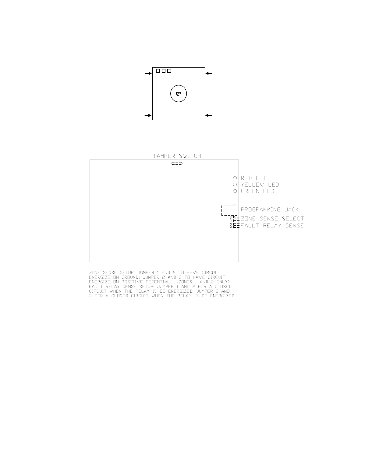
SETTING THE JUMPER OPTIONS (Set Before Installing)
Removing The Cover
Remove the 7720PLUS’s cover by inserting a screwdriver into the 4 removal points at the bottom of
the unit and gently releasing the locking tabs from the cover slots as shown.
.
(J2) Zone Inputs Activate on High or Low
If using zone input connections, set the J2 jumper so that zone 1 & 2 inputs are activated either with
a ground or with a positive voltage, whichever is required.
If the trigger level is set for positive voltage, +4.5 to +14.2 volts must be applied to zones 1 & 2 to
trigger an alarm. If the zone is connected to a normally high voltage trigger (i.e. goes low on alarm),
invert this zone when programming (questions 13 and 14).
If ground is selected, zones 1 & 2 are internally pulled up to 5 volts through a 10k ohm resistor. This
voltage should normally be pulled down (closed contact to ground) and released for alarm (opening the
contact). If a normally open contact is being used, invert this zone when programming (questions 13
and 14).
(J3) Fault Output Select
Refer to the diagram on the following page when setting jumpers.

– 8 –
The radio fault output relay may be programmed for either FAIL-SAFE mode (relay always
energized) or LOW CURRENT mode (relay normally de-energized) by selecting Yes or No to
programming question 27: FLT REL ON (Y/N). In addition, the relay can be set for either N.O. or N.C.
operation (in either fail-safe or low current modes) using the J1 jumper. When fail-safe mode is
selected, the relay will change states (and trigger a dialer, if connected) in the event of power loss.
Note that fail-safe mode increases the standby current by about 10mA, which results in lower battery
backup time (about 15%) in the event of power loss. Set the J1 jumper to position A or position B, as
follows:
Prog. Ques. 26 J1 Jumper Setting (relay N.O. or N.C.)
Fault Relay ON (energized) Pos. B Pos. A
NO N.C. N.O.
YES N.O. N.C.

– 9 –
Trigger voltage outputs: A current-limited source of approximately 12 volts DC is available at pin 3
of the terminal block, for external contacts, etc., that require a pullup voltage.
NOTE: Use color-coded wires for the power connections; it is recommended that the positive connection
be red and the negative connection be black.
Wiring At The Control Panel
’.
Connect the negative wire to the system negative point, which is also the negative line from the
battery.
Run the alarm wires to the transmitter location.
Wiring For ECP Communication with a Control Panel
Only certain panels support ECP data communication at this time. Check the Installation
Instructions of your panel to see if Long Range Radio is supported.
ECP data connections are the Data In and Data Out terminals that the keypads and other peripheral
devices (RF Receiver, VIP module, etc.) use for communication with the panel. To wire the radio for
ECP communication, do the following:
Connect TB1-4 (Ground) of the 7720PLUS to the ground of the panel.
Connect TB1-5 (ECP DATA IN) of the 7720PLUS to “data out to consoles” connection on the panel.
Connect TB1-6 (ECP DATA OUT) of the 7720PLUS to “data in from consoles” connection on the panel.
Note: add ground wire to drawing below. (See page 10a)

– 10 –
– 11 –
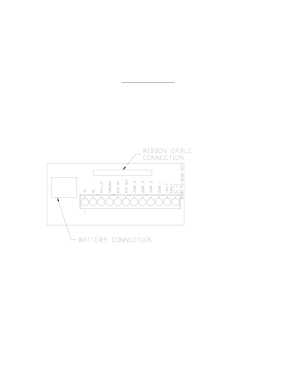
Recommended Wiring At The 7720PLUS
The alarm and power wires can be brought into the transmitter through the base, or through the
cover. If they are to be brought through the cover, cut out the optional wire entry port. Connect the
AC power wires from the transformer to TB 1-1 and TB 1-2, respectively. Install the battery into the
battery holder, but do not plug in the battery cable yet.
Maximum Wire Run Lengths
Gauge Distance
18 300 feet
20 200 feet
22 125 feet
—7720PLUS wiring connection TERMINALS—
Mounting
Determine the best antenna location for strong radio communication with the Master Station network
using the 7715DFFAST Tool (see pages 21 - 23). Mount the 7720PLUS to a horizontal or vertical
surface, depending on the antenna used. Be sure to allow access to the programming port when
mounting. The 7720PLUS is intended to be mounted to a horizontal surface, preferably on a ceiling,
or in an attic location on top of a joist when using the supplied wire antenna. If using the 7720ANT
antenna kit, the 7720PLUS can be mounted to a vertical surface such as a wall or beam.
Powering Up
After all wiring is complete and the unit is mounted, plug the battery cable of the 7720PLUS into
the connector next to the terminal block, then apply power to theradio. The radio will rapidly flash
each LED consecutively for a total time of about 2.5 seconds. During this time, the user can configure
the radio to operate in zone mode (four zone inputs) or in ECP mode, where alarm input is received
from the control panel via the ECP interface. See “Choosing Mode” in the Programming Section.

– 12 –
PROGRAMMING THE 7720PLUS
Using A 7720P Programming Tool
The 7720P Programming Tool is powered by the 7720PLUS, and connects to the telephone connector
on the 7720PLUS PC Board. Please note the the 7720P is not functional when the radio is running in
ECP mode; it is functional only during power-up of an ECP radio.
IMPORTANT NOTE: Some of the older 7720P tools (those shipped prior to mid-1998) will
not function if the line voltage is too low. These can be modified using instructions
supplied on request, or they may be returned to Ademco for factory modification. All 7720
P tools currently shipping will work without difficulty.
Each key of the 7720P has two possible functions, a normal function and a SHIFT function. To
perform a normal key function, simply press the desired key. To perform a SHIFT key function, press
SHIFT key, then press desired function key.
7720P Normal & Shift Key (shift LED lit) Functions
Key Normal Key Function SHIFT Key Function
BS/ESC [BS]: Press to delete entry [ESC]: Press to quit program mode.
Also, can reset EEPROM defaults*
↓ / ↑ [↓]: Scroll down programming [↑]: Scroll up programming
N/Y [N]: Press for “NO” answer. [Y]: Press SHIFT-Y for “YES”
answer
SHIFT Press before pressing a SHIFT key function. Will light SHIFT LED.
LED goes out once a key is pressed. Press again for each SHIFT function
desired.
1/A [1]: For entering the number 1 [A]: Used for entering C.S. ID
number
2/B [2]: For entering the number 2 [B]: Used for entering C.S. ID
number
3/C [3]: For entering the number 3 [C]: Used for entering C.S. ID
number
4/D [4]: For entering the number 4 [D]: Used for entering C.S. ID
number
5/E [5]: For entering the number 5 [E]: Used for entering C.S. ID
number
6/F [6]: For entering the number 6 [F]: Used for C.S. ID & FAST mode
7/S [7]: For entering the number 7 [S]: Press to display diagnostic
status
8/T [8]: For entering the number 8 [T]: Press to send TEST messages
9/X [9]: For entering the number 9 [X]: Press to reset the 7720PLUS
(Zone mode only)
✱/SPACE [✱]: Not used with 7720PLUS [SPACE]: Not used with 7720PLUS
0 [0]: For entering the number 0 No SHIFT function
#/ENTER [#/ENTER]: Press to accept entries No SHIFT function
• Active only when the “REVIEW?” prompt is displayed.
CHOOSING MODE: ECP OR ZONE
Using the 7720P, the user can enter the configuration set-up by pressing the enter key while the
individual LEDs rapidly flash sequentially. This will cause the radio to display the following prompt
on the 7720P display:
ECP Radio[Y/N]

– 13 –
The radio will wait 10 seconds for a response. If the radio receives no response or something other
than a “Y” or an “N”, the radio will use the configuration stored in EEPROM. The default
configuration is Zone mode. If the configuration has changed, the EEPROM MUST be
reprogrammed.
If the new configuration is ECP mode, and the panel used is not capable of programming the radio,
the 7720P can be used during the power-up sequence (See ECP Mode Unique Programming section,
page 18). If the new configuration is zone mode, the 7720PLUS signon will appear immediately and
programming may begin. If the 7720PLUS has been programmed for the given configuration, the
LEDs will flash according to their functions. If the 7720PLUS has not been programmed, regardless
of configuration, the LEDs will flash in unison indefinitely.
Zone Mode Unique Programming
After connecting the 7720P cable, power up the 7720PLUS (plug in the battery connector and apply
power to the control panel). The following will be displayed:
ADEMCO 7720 4.xx
© Pittway 1996
4.xx = current software revision level
Programming is accomplished by answering displayed questions. Most questions require only a [Y]es
or [N]o response, while others require a numerical response (ID numbers, etc.). Press ENTER to
accept each response and proceed to the next question. A “?” indicates an invalid entry. The current
value is displayed on the second line in parenthesis (). To accept the current entry, simply press the
ENTER key. Use the UP/DOWN arrow keys to scroll through the programming questions without
changing any values.
Enter programming mode by pressing [ENTER] during the initial power up period (while LEDs are
flashing consecutively).
Pressing SHIFT-X will reset the 7720PLUS to its initial power up phase if it has already entered
program mode. The 7720PLUS reads its EEPROM to determine its pre-programmed parameters. A
CRC of the EEPROM locations is also read. If the computed CRC does not match the one read from
EEPROM or if the programming parameters are invalid, the 7720P LCD displays “NO PROG”. While
the three LEDs flashes in unison, press ENTER to begin programming.
“”
“”
“”
“”
“”
Password Protection
If desired, the programming options can be passweord protected.
NOTE: If using a terminal to program passwords, use only those characters available on the 7720P.
This allows later access using a 7720P Programming Tool (A, B, C, D, E, F, S, T, X).
Once a password is assigned, the following prompt appears upon entering programming mode:
ENTER PASSWORD:
See EXITING PROGRAM MODE paragraph later in this section for assigning and changing
passwords.

– 14 –

– 15 –
SUBSCRIBER INFORMATION
Question 1 ID # Enter the 4-digit customer account number, 0001-9999.
Question 2 Odd (Y/N) Enter Y for Odd flag (bit value 1), N for even system flag (bit
value 0).
Question 3 15 MIN SUPV (Y/N) Status reporting is always enabled. Enter the desired
interval as follows:
Y = Short form: every 15 minutes (6-hour window for
COM-FAIL report)
N = Short form: every hour (standard 24 hour reporting for
COM-FAIL)
AlarmNet SYSTEM USERS (Private system users skip to #6)
Question 4 AlarmNet (Y/N) Enter Y if an AlarmNet installation. Enter N for Private
System users (skip to option #6).
Question 5 CS ID Enter the primary central station’s system ID number, 1-7F.
Not applicable for Private System users.
PRIVATE SYSTEM USERS (AlarmNet users skip to #8).
Question 6 Routing Code Enter the Private System routing code, 0-7. Not applicable
for AlarmNet users.
Question 7 Private Chnl# Enter the Private System channel number, 1-F. Not
applicable for AlarmNet users.
Question 8 Channel# Enter the AlarmNet channel number, 1-14.
PULSE/DELAY ZONE SELECTION
By configuring a zone as a pulsed zone, it is possible to use the output of a panel bell/siren driver to
activate the radio directly when the signal from this driver is a pulsed output for fire and a continuous
output for Burglary. To implement a Fire/Burg. detection at the radio, connect the driver output directly
to two zones on the 7720PLUS. Program the Fire zone as a pulsed zone and the Burglary Zone as a
delayed Zone (this is to prevent this zone from reporting an alarm when the pulsed signals are detected).
The number of pulses and the length of delay will be dependent on the particular panel or siren driver
being used and is therefore a programmable feature.
Note: Zones programmed for pulse cannot be designated as open/close or Telco zones; an invalid entry
message will occur, since the pulse zone takes priority over open/close and Telco programmed zones.
UL Note: The control unit total delay shall not exceed 14 seconds in UL Listed applications if “yes”; 0.30
seconds if “no”.

– 16 –
Question 9a Pulse Z1 (Y/N) Press Y if zone 1 is connected to a pulsed bell output. Question 9c will
appear. If N is pressed, the following appears.
Question 9b Z1 Delay
(00-127)
Enter the reporting delay from 1-127 seconds for
zone 1. Enter 00 for no reporting delay.
Question 9c Pulse Cnt? (Y/N)
(03 - 254)
If Pulsed Zone is answered Y, the next question will
be Pulse Cnt? Input the number of pulses required
to place the zone in alarm. Default is (03).
Question 10a Pulse Z2 (Y/N) Press Y if zone 2 is connected to a pulsed bell output. Question 10c will
appear. If N is pressed, the following appears.
Question 10b Z2 Delay
(00-127)
Enter the reporting delay from 1-127 seconds for
zone 2. Enter 00 for no reporting delay.
Question 10c Pulse Cnt? (Y/N)
(03 - 254)
If Pulsed Zone is answered Y, the next question will
be Pulse Cnt? Input the number of pulses required
to place the zone in alarm. Default is (03).
Question 11a Pulse Z3 (Y/N) Press Y if zone 3 is connected to a pulsed bell output. Question 11c will
appear. If N is pressed, the following appears.
Question 11b Z3 Delay
(00-127)
Enter the reporting delay from 1-127 seconds for
zone 3. Enter 00 for no reporting delay.
Question 11c Pulse Cnt? (Y/N)
(03 - 254)
If Pulsed Zone is answered Y, the next question will
be Pulse Cnt? Input the number of pulses required
to place the zone in alarm. Default is (03).
Question 12a Pulse Z4 (Y/N) Press Y if zone 4 is connected to a pulsed bell output. Question 12c will
appear. If N is pressed, the following appears.
Question 12b Z4 Delay
(00-127)
Enter the reporting delay from 1-127 seconds for
zone 4. Enter 00 for no reporting delay.
Question 12c Pulse Cnt? (Y/N)
(03 - 254)
If Pulsed Zone is answered Y, the next question will
be Pulse Cnt? Input the number of pulses required
to place the zone in alarm. Default is (03).

– 17 –
INVERTED ZONE SELECTION
Zones 1-4 and the test zone can be programmed for inverted input signals.
Question 13 Invert Z1 (Y/N) Press Y to invert the input signal for zone 1. Press N for normal input
signal.
Question 14 Invert Z2 (Y/N) Press Y to invert the input signal for zone 2. Press N for normal input
signal.
Question 15 Invert Z3 (Y/N) Press Y to invert the input signal for zone 3. Press N for normal input
signal.
Question 16 Invert Z4 (Y/N) Press Y to invert the input signal for zone 4. Press N for normal input
signal.
Question 17 Invert Test (Y/N) Press Y to invert the input signal for the test zone. Press N for normal
input signal
RESTORAL REPORTING ZONE SELECTION
Restoral reporting can be enabled, disabled or delayed. The delay option delays Restoral reporting for
about 1.5 minutes after the actual restore condition, which helps ensure that alarm messages reach the
central station before the restore message. Note that if restores are enabled for a delayed zone, the
restore condition must exist for at least 2.5 seconds (this is intended to prevent swinger conditions). If
any of the zones have been programmed for pulse operation, then, following the Restoral question, the
7720P will display “REST ON CHG (Y/N)”. This feature is used for zones connected to the bell output of a
panel, and when enabled (Y) will report the zone in restoral when the pulse train stops and a steady state
level, either high or low, is left on the zone input or when the steady state level starts pulsing. If this
feature is not enabled (N), the zone will only restore on a steady state low logic level.
Question 18 Rest. Z1 (Y/N/D) Press Y to enable restoral reporting for zone 1. Press N to disable
restoral reporting. Press D for delayed reporting.
Question 18a Rest. On CHG (Y/N) Press Y if restore is to be sent when the type of
signal changes, i.e., when pulsing state
changes to a steady state level (high or low) or
when a steady state changes to a pulsing state.
Restore normally occurs when the opposite
steady state occurs, e.g., when a steady state
high goes low.
Question 19 Rest. Z2 (Y/N/D) Press Y to enable restoral reporting for zone 2. Press N to disable
restoral reporting. Press D for delayed reporting.
Question 19a Rest. On CHG (Y/N) Press Y if restore is to be sent when the type of
signal changes, i.e., when pulsing state
changes to a steady state level (high or low) or
when a steady state changes to a pulsing state.
Restore normally occurs when the opposite
steady state occurs, e.g., when a steady state
high goes low.
Question 20 Rest. Z3 (Y/N/D) Press Y to enable restoral reporting for zone 3. Press N to disable
restoral reporting. Press D for dalayed reporting.
Question 20a Rest. On CHG (Y/N) Press Y if restore is to be sent when the type of
signal changes, i.e., when pulsing state
changes to a steady state level (high or low) or

– 18 –
when a steady state changes to a pulsing state.
Restore normally occurs when the opposite
steady state occurs, e.g., when a steady state
high goes low.

– 19 –
Question 21 Rest. Z4 (Y/N/D) Press Y to enable restoral reporting for zone 4. Press N to disable
restoral reporting. Press D for delayed reporting.
Question 21a Rest. On CHG (Y/N) Press Y if restore is to be sent when the type of
signal changes, i.e., when pulsing state
changes to a steady state level (high or low) or
when a steady state changes to a pulsing state.
Restore normally occurs when the opposite
steady state occurs, e.g., when a steady state
high goes low.

– 20 –
OPEN/CLOSE, TELCO & TAMPER ZONE SELECTION
Question 22 O/C Zone Enter the open/close reporting zone number, 1-4. A [0] entry
disables open/close reporting. If the zone selected was programmed
to be a pulse zone, (see Questions 8-11), this zone number selection
is invalid and will be tagged as an error.
Question 23 Telco Chan Enter the physical Telco line fault zone, 1-4. A [0] entry disables
Telco detection. If this zone is the same as the open/close zone,
this selection will automatically be set to “0” and Telco
detection will be disabled. If the zone selected was programmed
to a pulse zone (see Questions 8-11) this zone number selection is
invalid and will be tagged as an error.
Question 24 Tamper zone Enter tamper zone, 5-8. A [0] entry disables tamper detection. If
tamper is enabled, delayed restores will be automatically
generated.
Question 25
.HS Ant. Tst (Y/N) Press Y for 135 second interval antenna test. Press N if no antenna
test is desired.
Question 26
.AC Loss RPT (Y/N) If AC LOSS RPT is answered yes (Y), the radio will report the loss
of AC voltage within a 10 to 40 minute window, from its detection.
If this feature is disabled (N), this message will be suppressed.
NOTE: In either case, low battery messages will be sent as
detected.
Question 27 FLT REL ON (Y/N) Press Y if fail-safe mode is desired. In this mode, the fault relay is
normally energized and will de-energize in the event of a radio
fault. Note that fail-safe mode draws slightly more standby
current. See the SETTING THE JUMPERS section for setting the
relay output.
Question 28 Flt Latched(Y/N) Press Y if radio fault line is to be latched high upon detection of
transmission error. Press N if a momentary closure upon detection
of transmission error is desired.
REDUNDANT CENTRAL STATION REPORTING
Question 29 2nd CS (Y/N) Press Y if redundant reporting to a second central station is
desired. Press N if not desired (skip to end).
Question 30 2CS Z1 (Y/N) Press Y to enable reporting to second central station for
zone 1. Enter N to disable reporting.
Question 31 2CS Z2 (Y/N) Press Y to enable reporting to second central station for
zone 2. Enter N to disable reporting.

– 21 –
Question 32 2CS Z3 (Y/N) Press Y to enable reporting to second central station for
zone 3. Enter N to disable reporting.
Question 33 2CS Z4 (Y/N) Press Y to enable reporting to second central station for
zone 4. Enter N to disable reporting.
Question 34 2CS Test (Y/N) Press Y to enable test reporting to second central station.
Enter N to disable reporting.
Question 35 2CS Tamp (Y/N) Press Y to enable tamper reporting to second central
station. Enter N to disable reporting.
Question 36 2CS Sys Rpt (Y/N) Press Y to enable reporting of system report to second
central station. Enter N to disable reporting.
Question 37 2nd ID # Enter the 4-digit customer account number for the second
central station, 0001-9999.
Question 38 2nd CS ID Enter the second central station’s system ID number, 01-7F.
This ID number must be different from the one
programmed in question 5 (the Primary CS ID).

– 22 –
EXITING PROGRAM MODE, SETTING DEFAULTS & ASSIGNING PASSWORDS
When the last question is answered, all entries are validated by the system. If no errors are found, the
following is displayed:
REVIEW?
To review the programming options (to ensure that the correct responses have been made), press Y.
The programming questions will be displayed again, starting with question 1. Use the UP/DOWN arrow
keys to scroll through the program fields without changing any of the values. If a value requires change,
simply type in the correct value. When the last field is displayed, the REVIEW? question again appears.
If errors are found during the validation routine (values are out of range or there is a conflict of
parameters), the REVIEW? question is replaced by the following:
ERRORS FOUND
HIT ANY KEY
Upon hitting any key, the first invalid entry is displayed.
Correct the entry then press ENTER to display the next
invalid entry. When the last invalid entry is corrected, the
system again performs a validation routine. If no errors are
found, the REVIEW? question is displayed.
To display all program entries (not only invalid entries)
press the up arrow key. The previous question appears. Use
the down arrow key to display subsequent programming
entries.
Setting Factory Defaults: The programming options can be globally reset to their factory default
values by pressing ESC at the REVIEW? prompt. A confirmation prompt will appear. Press Y to reset,
or press N to return to the REVIEW? prompt. If Y is pressed, all programmed values will be reset to
their original factory settings.
To exit program mode & assign passwords, press N in response to the REVIEW? question. If no
password has been assigned, the following appears:
ENTER PASSWORD?
[Y/N]
Passwords can be used to split the programming questions into
two menus. See PASSWORD PROTECTION paragraph earlier
in this section. If a password is desired, press Y. The following
prompts appear. Press N if no passwords are desired.
ENTER PASSWORD: Enter the desired password (up to 4 digits max).
Verify Password Re-enter the password for confirmation.
NOTE: If using a terminal to program passwords, use only those characters available on the 7720P, to
allow later access using a 7720P (A, B, C, D, E, F, S, T, X).

– 23 –
If a password has already been assigned for the current programming menu, the ENTER
PASSWORD? prompt is replaced by the following:
CHG PASSWORD?
[Y/N]
Press Y or N, depending on whether you want to change the
password for the current programming menu. If [Y]es, you
will be prompted to enter the new password twice (as
confirmation). To clear an existing password, answer “Y” to
the “change password” prompt, but press only the ENTER
key when prompted for the new password and its
confirmation.
When the password question(s) have been answered, the system exits program mode and returns to
normal mode. The Programming Tool can then be disconnected, or can be used to trigger test
messages. Refer to the TESTING THE 7720PLUS section.
NOTE: Older programming tools {shipped prior to mid-1998 and not modified) cannot be used to send a
test message; they will cause a reset condition. Use the test message posts on the radio to send a test
message without using the 7720P.
ECP MODE UNIQUE PROGRAMMING
If ECP mode has been selected and the control panel being used does not support programming mode
(e.g. VIA30+), the 7720P can be used to program the radio. To enter programming mode, the
<ENTER> key of the 7720P must be pressed during the sequential flashing of the LEDs. The
following sign-on message will be displayed for one second:
7720ECP xxx
(c)Pittway 1999 xxx = current software revision level
All displayed questions must be answered. The subsequent question will not be displayed until the
current question is answered. Unlike the case of the Zone mode, pressing <ESC> will not bring the
list of programming questions to the end, if any question has been left unanswered.
Question 1 Device Addr Enter the Device Address of the radio. For VIA 30+, VISTA 10 and
VISTA 20 families, this must be 3. For other control panels, see the
panel’s installation instructions.
Question 2 ID# Enter the 4-digit customer account number, 0001-9999.
This account number will appear in the messages generated by the
radio. Messages generated by the panel will contain the subscriber ID
number programmed in the panel.
Question 3 Odd (Y/N) Enter Y for Odd flag (bit value 1), N for even system flag (bit value 0).
Question 4 15 MIN SUPV (Y/N) Status reporting is always enabled. Enter the desired interval as
follows:
Y = Short form: every 15 minutes (6-hour window for COM-FAIL
report)
N = Short form: every hour (standard 24 hour reporting for COM-
FAIL)

– 24 –
Question 5 CS ID Enter the primary central station’s system ID number, 1-7F
Question 6 Channel# Enter the AlarmNet channel number, 1-14
Question 7 HS Ant. Tst (Y/N) Press Y for 135 second interval antenna test. Press N if no antenna
test is desired.
Question 8 AC Loss RPT (Y/N) If AC LOSS RPT is answered yes (Y), the radio will report the loss of
AC voltage within a 10 to 40 minute window, from its detection. If
this feature is disabled (N), this message will be suppressed. NOTE:
In either case, low battery messages will be sent as detected.
Question 9 USE RADIO # (Y/N) If Y is selected, the Radio ID number will replace the panel Subscriber
ID in panel-generated messages.
If N is selected, the radio will send panel-generated messages with the
panel Subscriber ID number.
Question 10 2nd CS ID This must be programmed with a value, even if it is the same as the
primary central station. The control panel has the option to send a
selected message to the second central station.
Question 11 REVIEW? Press “Y” to review the programming options and to ensure that the
correct responses have been made. Parameters can be changed during
review. Press “N” to end programming session.

– 25 –
ANTENNA MOUNTING
Selecting A Location
If Non UL installation, an antenna location which has reliable communications with at least one
base station with an uplink signal strength reading of “3” or greater may be used .
NOTE: Place a check mark [✔✔] in the “Single Site Supervision” box on the Subscriber
Contract.
For UL Grade “A” or Grade “B” installations, find an antenna location which has reliable
communication to at least two AlarmNet Base Stations with a minimum uplink signal strength
reading of “3”.
After determining the type of installation required (UL, Non UL) find an antenna location
within the premises. Locations can be found by utilizing the test mode of the 7720PLUS (see
TESTING THE 7720PLUS section), the 7715 FAST Tool or the 7920 series transceiver.
Notes On Antenna
Mounting 1. Optimum RF performance can usually be found at the highest
point within a building, with the fewest number of walls
between the radio and the outside of the premises.
2. Avoid mounting the antenna near other electronic devices. The following
table provides minimum distances. Highest RF energy is in the direct,
horizontal line of the antenna. Therefore, vertical separation (moving
electronic devices either higher or lower on wall) provides a higher level of
isolation from the radio.
Equipment Distance
Short range receiver 20 ft.
PIR 10 ft.
Control panel 25 ft.
FM radio or TV ant. 25 ft.
other devices 10 ft. minimum
The diagram below displays the 7720PLUS mounting options and the
appropriate antenna hardware to be used in each of these situations.

– 26 –
ANTENNA MOUNTING OPTIONS
Outdoor Antenna Mounting
The 7720PLUS must always be mounted indoors. If the only suitable antenna location found is
outside of the protected building, mount the 7720PLUS close to this location on the inside of the
building and connect an external (outdoor) antenna to the radio. Carefully follow all instructions
included in these optional parts to insure integrity of the weather-proof seals on all outside
connections. The following antenna kits can be utilized for remote or outdoor mounting.
Antenna Description Note
7720 ANT Adapter for the Remote Antenna
7625-3dB 3dB Gain Antenna omnidirectional
7825 Outdoor Antenna with bracket omnidirectional
7670F Remote Antenna bracket
7674 6dB Gain Direct directional
Indoor Antenna Mounting
If the location found allows indoor mounting of the antenna, then the antenna
selected depends on the mounting surface of the 7720PLUS. If it is possible to
mount the 7720PLUS on a ceiling or on an attic joist, you can use the included
wire antenna, which provides excellent performance (see Standard Wire
Antenna Mounting). If the only mounting surface available is a wall, you can
use the 7825DP (see Wall Mounting).
Standard Wire Antenna Mounting (omnidirectional)
1.Mount the 7720PLUS Subscriber
Radio on the ceiling or on an attic
joist.
2.Replace the 7720PLUS cover.
3.Push the antenna into the antenna
receptacle until it bottoms out.
4.The antenna should be vertical and
straight.
5.Rotate the antenna until it snaps into the
locked position. DO NOT BEND THE
ANTENNA!
Wall Mounting using the 7825DP (strongest signal is perpendicular
to the wall)
1.Mount the radio to a wall or other
vertical surface. Make sure the 3
LEDs are in the upper right hand
corner.
2.Replace radio’s cover.
3.Follow the Installation Instructions
included with the 7825DP for
mounting to the 7720PLUS
Subscriber Radio.

– 27 –
Wall Mounting with the 7625-3dB Gain and the 7720ANT Adapter.
1. Mount the 7720PLUS Subscriber
Radio.
2. Replace the radio’s cover.
3. Remove the plastic insert from the
cover by rotating it 45° counter-
clockwise.
4. Replace with the insert provided
with the antenna kit.
5. Mount the 7720ANT vertically
pointing either up or down, not to
the side.
6. Mount the 7625-3DB Gain directly
on to the 7720ANT.
7. Mount the plastic bracket (supplied)
to the wall 3 inches from the top of
the antenna.
Remote Antenna Mounting
1. Mount the 7720PLUS Subscriber Radio.
2. Replace the radio’s cover.
3. Mount the 7720ANT directly on to the 7720PLUS radio.
4. Mount antenna outdoors in the location determined earlier in this section.
5. Mount the ADEMCO antenna cables.
NOTES:
1. Use only ADEMCO Cables P/N 7626-5 (5’), 7626-12 (12’), 7626-25HC (25’) or
7626-50HC (50’).
2. Do not attempt to make the antenna cables yourself, and do not under any
condition try to splice them!
For detailed instructions on installing the above antenna kits, please read the enclosed
Installation Instructions.
Powering Up
After all wiring is complete and the unit is mounted, plug the
battery cable of the 7720PLUS into the connector next to the
terminal block.
Apply power to the radio.
The LEDs will flash consecutively for a brief time to allow entry
into programming mode. If the 7720PLUS has been programmed,
the LEDs will begin to flash according to their functions. If the
7720PLUS has not been programmed, the LEDs will flash in
unison indefinitely.

– 28 –
POST INSTALLATION CHECKLIST
Post Installation Checklist is intended for installers who want to get the 7720PLUS up and running
quickly.
To take full advantage of the many installation features of the 7720PLUS, we strongly suggest you take a
few moments and read the programming section.
Power-Up Always connect the battery first.
Weather Proofing All outside antennas and cable connections must be weatherproofed.
Antenna Positioning Make sure the 7625 antenna is vertically mounted. If installing the 7625
or 7674 antenna outside, use the 7670 Antenna Bracket and follow the
installation instructions enclosed.

– 29 –
TESTING THE7720PLUS
Radio Transmission Test
The 7720PLUS is capable of sending a test message, which can be received by the central station to
confirm the radio’s communication link to the central station.
For AlarmNet users, the test message will cause the master station network to send a “Field
Triggered Diagnostic Message” to the Central Station. This message provides network information as
well as signal strength and frequency characteristics of the transmitted messages. Refer to the
AlarmNet User’s Guide for detailed information concerning these messages. The test message can be
transmitted in any of three ways. Please note that methods 2 and 3 are available in Zone mode
ONLY. Check control panel Installation Instructions if LRR Test Mode feature is supported.
1) The TEST INPUT of the 7720PLUS can be triggeredby shorting the two pins of the test connector
together using a screwdriver, dime, etc., This will initiate a 90 second cycle (total of 60 messages) of
test message transmissions. Note that once this cycle has been initiated by a voltage trigger, it can be
turned off by using the T command described in (2). Otherwise, the messages will not stop until the
end of the cycle.
2) A 7720P Programming Tool can be used, if the radio is operating in zone mode. To begin the cycle
of test message transmissions, press SHIFT-8 (T command). This is a toggle function. To end the
transmissions before the end of the cycle, simply enter the command again. See the NOTE on page
25.
3) A computer terminal can be used, if connected to the programming connector of the 7720PLUS. To
begin a cycle of test message transmissions, press “T.” This is a toggle function. To end the
transmissions before the end of the cycle, simply enter the command again.
System Test
Trigger an alarm by any convenient means and observe the LED indicators on the radio. The yellow
LED should light solidly, followed by the green LED flashing every 1-3 seconds at first, then slowing
during the 6 minute cycle. This indicates that an alarm message has been received at the radio
(yellow), and the transmitter has been activated (green). The red LED should not light.
If the radio is configured for zone mode and the zone is programmed for restore, restore the circuit.
The yellow LED should light solidly, and the green LED should flash again, indicating transmission of
the restore message. The central station receiver should display alarm/restore messages for each
triggered alarm/restore performed.
If at any time the red LED lights, a radio fault has been detected. This could be caused by a faulty
antenna connection, or might be caused by low internal battery voltage, or a failure in the radio’s
power circuits (see LED FLASH PATTERNS on page 4).
If the radio is in Zone mode, the 7720PLUS can display diagnostic data (S command) related to the
status of these conditions. See Status Command section.
If the radio is in ECP mode, the status is displayed on the control panel’s remote keypad in the lower
right-hand corner. This display is in the form of a four-digit numeric output (usually preceded by
“Long Rnge Fail”). Please see description of codes in ECP Status Codes section.
Replace the cover (if it was removed) and perform a control panel system test.

– 30 –
Status Display Interpretation for “S” Command.(Available in Zone mode ONLY)The status of the
7720PLUS can be viewed on either a 7720P Programming Tool or an appropriate terminal when
either device is connected to the serial port of the 7720PLUS. The status display includes zone input
status, test terminal status, tamper status, battery condition, charging voltage status and radio fault
status, The 2-line display takes the following form:
1234 TeTmBaAcFlt
5555 5 5 + + 0
1234 The numbers 1-4 represent the four zone inputs, and follow
Ademco High Speed Format codes:
1 New Event
2 New Opening
3Restore
4 New Closing
5 Normal
6 Previously Reported Event
@ Telco New Event
P Telco Previously Reported
p Telco Restore
Te Test terminal input codes:
1 Test message transmission in progress, triggered
by either physical test point or “T” command.
5 Normal (no test message in progress).
6 Transmission of test message completed, but
physical test point still triggered.
P Transmission of test message pending completion
of higher priority message transmission .
Tm Tamper status follows High Speed Format codes above.
Ba Represents battery condition:
+ Battery voltage acceptable
- Battery voltage below 10.03V ±2%
V Battery voltage going low has not yet been detected low
for four consecutive transmissions
^Battery restoring, but not yet reported as restored
Ac Represents charging voltage:
+ AC voltage OK
- AC voltage bad & reported
V AC voltage bad, not reported (reporting window not
expired)
^AC voltage restored, not reported as restored
Flt Represents Radio Faults.
0Normal
1 Internal radio fault*
5 Radio Fault (Bad VSWRor low RF output (check
antenna, connections and cable) CRC
Ram/EEPROM corruption. Reset the radio and if
necessary reprogram. If this fault recurs, return radio for
service.
Code 1 requires factory service
Code 5 may require factory service if troubleshooting of power supply and antenna connections
does not correct problem.

– 31 –
ECP Status Codes
When the 7720PLUS radio is set up in ECP mode, it sends to the control panel the status of its
battery, the incoming AC voltage, the tamper and any RF failures. The status is displayed on the
control panel’s remote keypad in the form of a four-digit numeric usually preceded by the label “Long
Rnge Fail”. These codes will not clear from the remote keypad until a code-off sequence is entered
and the fault condition has cleared. The status codes are broken out as follows:
Status CodeExplanation
0000 Panel lost communication with the 7720PLUS radio
0400 7720PLUS Power On/Reset
3000 7720PLUS lost AC power input
0880 7720PLUS tamper detected (cover removed from radio)
0060 7720PLUS Battery is Low
(The following codes will never be combined; each is mutually exclusive)
0001 7720PLUS has internal radio fault and cannot transmit*
0005 7720PLUS Radio Fault (BadVSWR or low RF output.Check
antenna, connections and cable)
0006 7720PLUS EEPROM and/or RAM is corrupt (internal CRC is bad)*
0007 7720PLUS had not been programmed
Codes 1& 6 require factory service.

– 32 –
Last Detected Fault “E” Command
(Available in Zone mode ONLY)
The last detected radio fault and the last reported radio fault can be viewed by pressing “E” on a
7720P Programming Tool or an appropriate terminal when either device is connected to the serial
port of the 7720PLUS.
The message is a 2-line display where the top line identifies the last fault that the 7720PLUS detected
and the second line identifies the last fault that the 7720PLUS actually reported to the monitoring
network. The last detected fault represents a fault that occurred on at least one transmission, but
did not necessarily trip the fault relay. The last reported fault is a fault that was present for a
number of transmissions (typically at least 4 consecutive transmissions) and which tripped the fault
relay. The possible fault numbers are described in the “S” command paragraph above. If the detected
fault does not match the reported fault value, and the transmission cycle has finished, it indicates
that the fault was not present long enough for the radio to report the condition.
These values are stored in EEPROM and will be retained even when the 7720PLUS is powered down.
To erase the numbers from memory, press ESC (shift BS) as the next keystroke after pressing “E”.
The fault value is also erased automatically upon exiting program mode.
NOTE: Since the execution of this command requires access to the RJ11 connector, the antenna and
cover must be removed. By doing so, the radio will detect an RF fault as well as a tamper. To prevent
this fault from overwriting a previous fault, the radio does not write the last reported fault to
EEPROM if a tamper is detected.
Unique Contact ID Messages Generated in ECP Mode
The following is a list of messages generated by the 7720PLUS when it is in ECP mode. These
messages are in Contact ID format.
Message
Tramsmitted by
7720PLUS
Message
Displayed on 685 Description of Alarm
333008xx* R330 C8xx* Restore of any RF faults reported
to the panel.
(Restore of System Peripheral
Trouble).
134208xx*
334208xx* E342 C8xx*
R342 C8xx* ECP AC Loss
ECP AC Restore
133808xx*
333808xx* E338 C8xx*
R338 C8xx* ECP Low Battery
ECP Low Battery Restore
133908xx* E339 C8xx* ECP Power On/Reset
134108xx*
334108xx* E341 C8xx*
R341 C8xx* ECP Tamper
ECP Tamper Restore
13550000
33550000
E355 C000
R355 C000
Radio Lost Communication with
the Control Panel
Radio Re-established
communication with the Control
Panel
Note: “xx” is the Device Address programmed in the 7720PLUS radio. (see ECP Unique Programming
section).

– 33 –
TROUBLESHOOTING
Problem Probable Cause Solution
No signals received AC power not available and
battery dead.
Wall power pack defective.
Verify that wall outlet is live and
voltage is between 102 and 138
VAC.
Verify approximately 12 volts AC
across terminal block positions 1
and 2.
Replace power pack.
Antenna Location See page 21-23 for selecting
Antenna locations.
Programming (Subscriber #,
Central Station ID #, or O/E) Verify and correct programming
entry.
Radio Fault If you have a 7720P, see page 26
If you don’t have a 7720P, see
page 4 (LED FLASHING).
Low Battery and AC not
connected. Apply AC voltage to radio for
approximately 2 hours to charge
battery. If this fails, replace
battery.
Environment If temperature exceeds -30°C to
60°C,radio may not perform
correctly. Mount radio in
temperate area.
Relocate the 7720PLUS by using
the Remote Antenna Kit.
Central Station is not receiving
Alarms. No connection to ground Connect common ground from
trigger output of panel to TB 1 Pin
4.
Incorrect trigger input. Verify type of input.
Application of +4.5 to 12 volts
(Non-Inverted).
Absence of +4.5 to 12 volts
(Inverted).
Incorrect Jumper settings. See Setting the Jumper Options:
J2 Zone Sense Input

– 34 –
SPECIAL NOTES FOR U.L. INSTALLATIONS
The 7720PLUS Subscriber Unit can be used in systems Listed by Underwriter’s Laboratories for Grade A
and Grade B Central Station Mercantile Burglary. The following additional requirements must be observed
for the installation of subscriber remote equipment in such systems:
1. Installation must be in accordance with the National Electrical Code, UL611 and UL681.
2. The 7720PLUS is intended to be connected to dry contact and voltage trigger outputs of a Listed compatible
control unit.
3. The 7720PLUS must be programmed as follows:
a) This product is not Listed for Fire Alarm Service. Therefore, zones should not be programmed as pulsed
(programming questions 9a, 10a, 11a, 12a).
b) Delayed reporting should be programmed as 00 (programming questions 9b, 10b, 11b, 12b).
c) Restoral reporting must not be disabled (programming questions 18, 19, 20, 21).
d) The Telco channel must be enabled. Do not enter 0 (programming question 23).
e) A tamper zone must be enabled (programming question 24). The tamper switch shall be enabled and
mapped to a 7720PLUS zone. (Tamper is automatically configured in ECP configured radios.)
f) The High Security Antenna Test option must be programmed as YES (programming question 25). The
default is once every 135 seconds.
g) AC Loss Reporting must be programmed as YES (programming question 26).
h) The Fault Relay On option must be programmed as YES (programming question 27).
i) The Fault Relay Latched option must be programmed as YES (programming question 28).
4. FOR GRADE A CENTRAL STATION INSTALLATIONS: A UL Listed communicator must monitor the
radio fault output (terminals 11 & 12) of the 7720PLUS. A No. 659EN Telco Line Monitor’s output should be
connected to an input zone of the 7720PLUS unit. The 659EN shall be inside the control enclosure. Premises
openings and closings should be sent via the communicator. The fault relay (question 26) shall be
programmed as fail-safe (fault relay ON) and jumper J1 shall be set in “A” position (normally closed). In
addition, the installation must meet the requirements defined for GRADE B CENTRAL STATION
INSTALLATIONS defined below.
5. FOR GRADE B CENTRAL STATION INSTALLATIONS: All wiring between the 7720PLUS and the
Listed control panel must be enclosed in rigid conduit (outside walls) or flexible conduit (inside walls or above
ceilings). The control unit shall be a Listed Grade A Local Burglar Alarm Unit/Police Connect Unit.
6. FOR POLICE STATION CONNECTED INSTALLATIONS: Same requirements as for GRADE A
CENTRAL STATION INSTALLATIONS defined above, except that the control panel must be Listed for
GRADE A POLICE CONNECT, and premises openings and closings do not need to be sent via the
communicator.
7. All wiring not run in conduit shall be contained within the same room as the 7720PLUS.
Specifications
Dimensions: 8.5” x 9.5” x 1.7”.
Power: 120 volt AC ±15% to wall power pack; wall power pack provides unregulated AC
voltage of approximately 12 volts to radio.
Power required: 40 VA, peak, during rf transmission.
Battery: Ademco 7720BT, 12VDC, 800 mAH
Fuse: Internal self-resetting solid state fuse, 3 Amp rating.Fault Relay Output: 30V, 1A
Trigger Voltage Outputs: 12 VDC, nominal.
Input triggering levels: Zones 1 & 2: selectable 0 volts or 4.5 to 14.2 volts into 10k ohms
Zones 3 and 4: 4.5 to 12 volts into 10k ohms
RF power output: 5 watts nominal
Frequency band: 928.0125 MHz to 928.3375 MHz, 25 KHz channels
Frequency selection: Programmable at installation to any one of 14 available channels.
Frequency accuracy: + 2.5 PPM.
Operating temp: -30 to +60 deg. Celsius.
Storage temp: -40 to +70 deg. Celsius.

– 35 –
Humidity: 90% relative humidity, non-condensing
Altitude: to 10,000 ft. operating, to 40,000 storage.
Antenna: Integral 5/8 wave whip.
Optional external Type N connector

– 36 –

– 37 –
“FEDERAL COMMUNICATIONS COMMISSION
(FCC) STATEMENT”
This equipment has been tested to FCC requirements and has been found acceptable for use. The FCC
requires the following statement for your information:
This equipment generates and uses radio frequency energy and if not installed and used properly, that is, in
strict accordance with the manufacturer’s instructions, may cause interference to radio and television
reception. It has been type tested and found to comply with the limits for a Class B computing device in
accordance with the specifications in Part 15 of FCC Rules, which are designed to provide reasonable
protection against such interference in a residential installation. However, there is no guarantee that
interference will not occur in a particular installation. If this equipment does cause interference to radio or
television reception, which can be determined by turning the equipment off and on, the user is encouraged to
try to correct the interference by one or more of the following measures:
• If using an indoor antenna, have a quality outdoor antenna installed.
• Reorient the receiving antenna until interference is reduced or eliminated.
• Move the receiver away from the transmitter.
• Move the antenna leads away from any wire runs to the transmitter.
• Plug the transmitter into a different outlet so that it and the receiver are on different branch circuits.
If necessary, the user should consult the dealer or an experienced radio/television technician for additional
suggestions.
The user or installer may find the following booklet prepared by the Federal Communications Commission
helpful:
“Interference Handbook”
This booklet is available from the U.S. Government Printing Office, Washington, DC 20402. Stock No.
The user shall not make any changes or modifications to the equipment unless authorized by the Installation
Instructions or User’s Manual. Unauthorized changes or modifications could void the user’s authority to
operate the equipment.
TO THE INSTALLER
Regular maintenance and inspection (at least annually) by the installer and frequent testing by the user are
vital to continuous satisfactory operation of any alarm system.
The installer should assume the responsibility of developing and offering a regular maintenance program to
the user as well as acquainting the user with the proper operation and limitations of the alarm system and
its component parts. Recommendations must be included for a specific program of frequent testing (at least
weekly) to insure the system’s proper operation at all times.
THE LIMITATIONS OF THIS RADIO COMMUNICATIONS SYSTEM
While this 900 MHz Long Range Radio communications system is part of an advanced and sophisticated
security system, it does not offer guaranteed protection against burglary or fire, nor does it guarantee
communication of burglary or fire warning signals to a central station. Any alarm system, or any
communications system, whether commercial or residential, is subject to compromise, or failure to warn, for
a variety of reasons. Examples of some of these reasons are:
• Intruders may gain access through unprotected openings or have technical sophistication to bypass an
alarm sensor, and then disconnect an alarm communicating radio transmitter.
• Signals sent by 900 MHz radio transmitters may be blocked by metal, mountains, hills, foliage and other
natural and man made obstructions before they are received by a master receiving station or sent to a
central station. Even a path previously verified as acceptable may periodically change its characteristics.
• Long-range radio communication transmitters will not work without power. Radio transmitters require a
battery to work properly in the absence of A.C. power. A weak or dead battery, or improperly installed
batteries may prevent these devices from functioning properly if A.C. power is disrupted for any reason.

– 38 –
• Radio communication systems are subject to external interference, natural or man-made, intentional or
coincidental, that may keep a signal or group of signals from being successfully received by a master
receiving station or a central station. In addition, one-way radio communication devices receive no
acknowledgment from a master receiving station that their signals are being successfully received.
Signals transmitted may clash with those transmitted from other systems. While statistical estimates
predict successful operation, if the guidelines in the system manuals are followed, the operation of this
system is still probabilistic in nature and may be subject to random signal failures.
• Radio communication devices may change their characteristics over time. Such parameters as frequency,
modulation and power should be properly monitored periodically, with required adjustments made by
qualified personnel.
• Radio communication devices must be installed by qualified personnel. Improper installation or selection
of a transmitter’s location may cause intermittent or unreliable performance.
Any electronic or mechanical device can fail. The most common cause of an alarm system or a radio
communications system not functioning properly when an intrusion or fire occurs is inadequate
maintenance, maintenance that is intended to find such failures as soon as possible. This alarm and
communication system should be tested weekly to be sure all sensors and transmitters are working properly.
Installing an alarm system may make one eligible for lower insurance rates, but an alarm system is not a
substitute for adequate insurance. Homeowners, property owners, business owners and renters should
continue to insure their property and lives.

– 39 –
ADEMCO LIMITED WARRANTY
Alarm Device Manufacturing Company, a Division of Pittway Corporation, and its divisions, subsidiaries and affili-
ates (“Seller”), 165 Eileen Way, Syosset, New York 11791, warrants its products to be in conformance with its own
plans and specifications and to be free from defects in materials and workmanship under normal use and service
for 18 months from the date stamp control on the product or, for products not having an Ademco date stamp, for
12 months from date of original purchase unless the installation instructions or catalog sets forth a shorter period,
in which case the shorter period shall apply. Seller’s obligation shall be limited to repairing or replacing, at its op-
tion, free of charge for materials or labor, any product which is proved not in compliance with Seller’s
specifications or proves defective in materials or workmanship under normal use and service. Seller shall have no
obligation under this Limited Warranty or otherwise if the product is altered or improperly repaired or serviced by
anyone other than Ademco factory service. For warranty service, return product transportation prepaid, to Ademco
Factory Service, 165 Eileen Way, Syosset, New York 11791.
THERE ARE NO WARRANTIES, EXPRESS OR IMPLIED, OF MERCHANTABILITY, OR FITNESS FOR A
PARTICULAR PURPOSE OR OTHERWISE, WHICH EXTEND BEYOND THE DESCRIPTION ON THE FACE
HEREOF. IN NO CASE SHALL SELLER BE LIABLE TO ANYONE FOR ANY CONSEQUENTIAL OR
INCIDENTAL DAMAGES FOR BREACH OF THIS OR ANY OTHER WARRANTY, EXPRESS OR IMPLIED, OR
UPON ANY OTHER BASIS OF LIABILITY WHATSOEVER, EVEN IF THE LOSS OR DAMAGE IS CAUSED BY
THE SELLER’S OWN NEGLIGENCE OR FAULT.
Seller does not represent that the products it sells may not be compromised or circumvented; that the products will
prevent any personal injury or property loss by burglary, robbery, fire or otherwise; or that the products will in all
cases provide adequate warning or protection. Customer understands that a properly installed and maintained
alarm may only reduce the risk of a burglary, robbery, fire or other events occurring without providing an alarm, but
it is not insurance or a guarantee that such will not occur or that there will be no personal injury or property loss as
a result. CONSEQUENTLY, SELLER SHALL HAVE NO LIABILITY FOR ANY PERSONAL INJURY, PROPERTY
DAMAGE OR OTHER LOSS BASED ON A CLAIM THE PRODUCT FAILED TO GIVE WARNING. HOWEVER, IF
SELLER IS HELD LIABLE, WHETHER DIRECTLY OR INDIRECTLY, FOR ANY LOSS OR DAMAGE ARISING
UNDER THIS LIMITED WARRANTY OR OTHERWISE, REGARDLESS OF CAUSE OR ORIGIN, SELLER’S
MAXIMUM LIABILITY SHALL NOT IN ANY CASE EXCEED THE PURCHASE PRICE OF THE PRODUCT,
WHICH SHALL BE THE COMPLETE AND EXCLUSIVE REMEDY AGAINST SELLER. This warranty replaces any
previous warranties and is the only warranty made by Seller on this product. No increase or alteration, written or
verbal, of the obligations of this Limited Warranty is authorized.
ALARM DEVICE MANUFACTURING CO.
A DIVISION OF PITTWAY CORPORATION
165 Eileen Way, Syosset, New York 11791
Copyright© 1996 PITTWAY CORPORATION