Ademco 7KULP Microwave/Passive IR Monitor Detector User Manual DT 556C1
Honeywell International Inc. Microwave/Passive IR Monitor Detector DT 556C1
Ademco >
User Manual
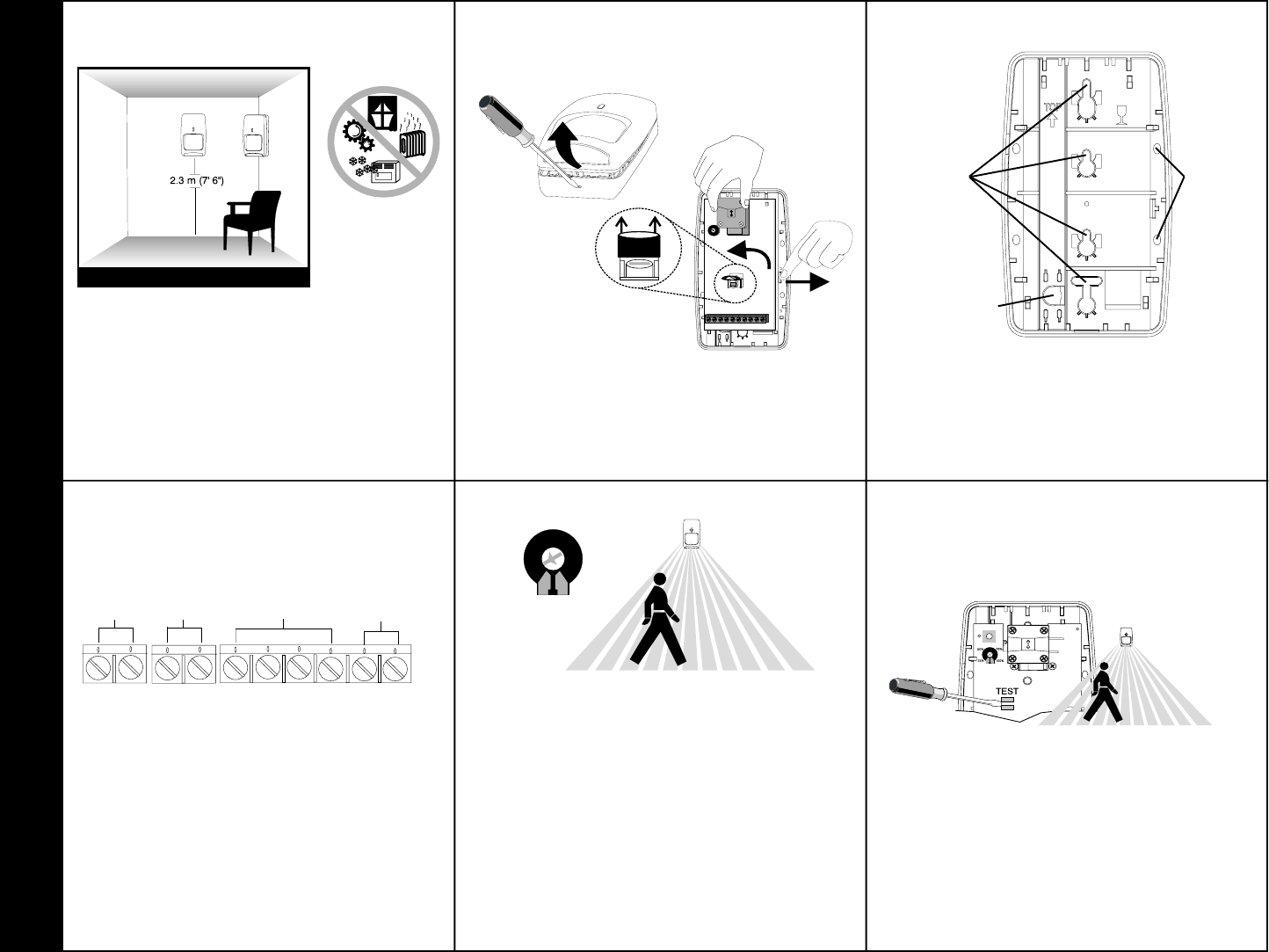
❶ Select the mounting location.
❹ Wire the unit.
❸ Mount the unit.
❺a Walk-test the sensor.
Mounting Location Guidelines
2.3 m (76) mounting height
Avoid direct or reflected sunlight
Aim sensor away from windows or heating/
cooling devices
Sensor must have a clear line-of-sight to
protected area
• Use a small screwdriver to unfasten the housing
latch. Gently pull apart the housings.
• Push outward on the PCB latch and lift the PCB
out of the housing.
• Slide the wire through the wire channel in the
back housing.
• Mount the back housing flat against a wall or in a
corner.
• Replace the PCB.
• Connect wires as shown using 0.3 - 1.0 mm2
(18 to 22 gauge) wire size. Observe proper
polarity.
• Set Switch 3 to select the appropriate fluorescent light
filter (see Dip Switch chart on the next page).
• Apply power to the unit. Initialization and mask
detection are complete when the LED stops flashing
slowly.
• Adjust the microwave range to minimum setting
(25%) by turning the range adjustment counterclock-
wise using a small screwdriver.
• Replace the front housing.
• Begin walking through the detection area.
- The LED will turn red, indicating an alarm detection.
• Increase the microwave range as necessary.
• Repeat the items in step 5a until proper detection
range is obtained.
❺b Optional: Walk-test using Zone Finder
• Use a screwdriver to short the test pads.
• During the Zone Finder walk-test mode, the LED
turns:
- green for one second for every PIR detection;
- yellow for two seconds for every microwave
detection.
• Adjust the microwave range as necessary.
• Zone finder mode times out after ten minutes.
Corner
Mount
Wire Channel
Wall Mount
75%
100%
25%
50%
DT-7550C DUAL TEC® Motion Sensor Installation Instructions
V+V-
NC
C
Alarm
125 mA
25 VDC
Power
40 mA
7.5-16 VDC
(For UL 8.0-16 VDC)
NO
T
T
Trouble
125 mA
25 VDC
Tamper
50 mA
24 VDC
TBLTBL EOL
Use the Zone Finder mode to identify the PIR and/or
microwave pattern. In Zone Finder mode the red LED
is disabled.
❷ Separate the sensor housings and
remove the printed circuit board (PCB).
For improved anti-mask
performance the look-down
mirror is disabled. To enable
look-down remove the mask.
PRODUCT SPECIFICATIONS
Range:
15 m x 18 m (50' x 60')
Alarm relay:
Energized Form C
125 mA, 25 VDC, 20 Ohm series resistor
Trouble relay:
De-energized Form B
(NC) 125 mA, 25 VDC
Tamper switch:
(NC) 50 mA, 24 VDC
Power requirements:
7.5 - 16 VDC (UL 8.0 - 16 VDC)
25 mA typical, 40 mA maximum, 12 VDC
AC Ripple: 3 V peak-to-peak at nominal 12 VDC
Microwave frequencies:
24.125 - 24.200 GHz
PIR white light immunity:
6,500 Lux typical
Fluorescent light filter:
50 Hz or 60 Hz selectable
RFI immunity:
30 V/m,10 MHz - 1000 MHz
Operating temperature:
0o to +55o C (-10o to +112o F)
5 - 95% relative humidity (non-condensing)
Self-test intervals:
Microwave Supervision Continuous
PIR self-test Once every hour
Temp. Comp. Every 30 seconds
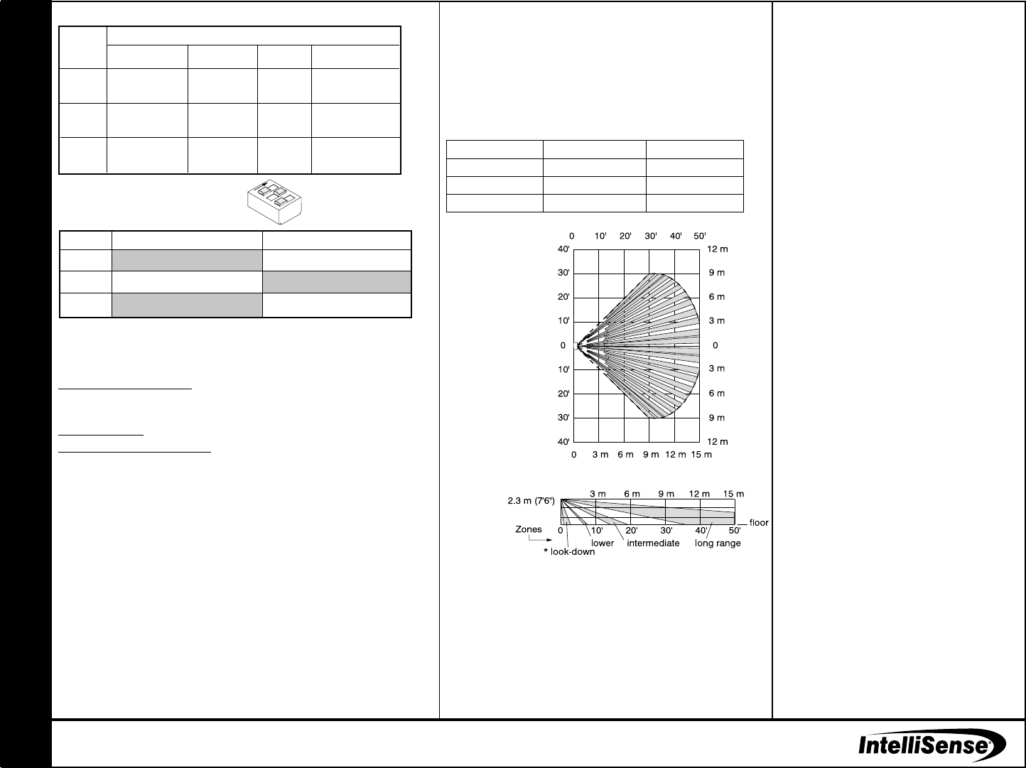
PIR fields-of-view:
Standard Wide Angle Lens
22 long range edges
12 intermediate edges
6 lower edges
* 4 Look-down edges
Dimensions:
11.9 cm H x 7.1 cm W x 4.2 cm D
(4.685" H x 2.795" W x 1.654" D)
Sensitivity:
Standard 3 - 4 steps
Intermediate 2 - 3 steps
Approvals/listings:
FCC
Copyright 2001, IntelliSense® All rights reserved.
5-051-642-00 Rev B
DUAL TEC is a registered trademark of Honeywell International, Inc.
All other trademarks are the properties of their respective owners.
www.cksys.com
LED INDICATORS
DIP SWITCH SETTINGS (SW1)
Factory default settings are shown in grey.
DETECTION PATTERNS
DT-7550C DUAL TEC® Motion Sensor Product Information
DT-7550C Side View
Wide Angle Lens
2
3
1
ON
TROUBLE SHOOTING
Problem: Red LED is flashing rapidly, trouble relay is actuated.
Explanation: The sensor is in one of three conditions:
Microwave supervision failure: The sensor continues operating using PIR as the only
detection method. When detection occurs on the PIR channel, the alarm relay will latch
open until the Microwave trouble is removed.
PIR self-test failure: Alarm relay does not actuate.
Temperature compensation failure: When alarm occurs, the alarm relay will latch open
until the trouble is cleared.
Solution: Power down the sensor or enter zone finder mode which will perform self-test.
If the trouble does not clear, replace the sensor.
Problem: Trouble relay is actuated without red LED flashing.
Explanation: Anti-mask condition is detected.
Solution: Verify that the sensor is not masked or blocked. Walk through the detection
pattern. Replace the sensor if it does not clear.
MASK FUNCTIONS
The DT-7550C detects a variety of masking materials and objects. When it determines
the presence of a mask, the DT-7550C sensor signals a trouble condition. Mask materials
may be detected up to one foot from the sensor.
A visual inspection and walk-test is recommended for all trouble signals. The sensor
clears a mask condition when it detects motion on the PIR and microwave technologies.
Refer to the Trouble Function chart for sensor operation.
LED
Red
Yellow
Green
Normal
ON
Alarm
ON
Microwave
ON
PIR
Power Up
Slow
Blink
OFF
OFF
Trouble
Fast
Blink
OFF
OFF
Zone Finder
OFF
ON
Microwave
ON
PIR
OPERATION MODE
Switch
1
2
3
OFF
Standard Sensitivity
LED disabled
60 Hz Fluorescent Filter
ON
Intermediate Sensitivity
LED enabled
50 Hz Fluorescent Filter
POWER UP ANTI-MASK (Patent Pending)
At power up, the DT-7550C looks for PIR activity. It signals the presence of
a mask if the PIR does not respond when microwave activity is detected.
NORMAL OPERATION
The DT-7550C signals a mask condition when reflective objects are placed
up to a foot in front of the sensor. Follow the mounting guidelines as shown
in Step 1.
DT-7550C Top View
Wall Mounted
Wide Angle Lens
Sensor Status
Normal
Self-test Failure
Mask
Trouble Relay
Closed
Open
Open
LED
Normal
Trouble Flash
Normal
TROUBLE FUNCTION
* Look-down fingers
are enabled only when
the look-down mask is
removed (see Step 2).
FCC Notice: This equipment has been tested and found to comply with the limits for a field disturbance sensor
pursuant to Part 15 of the FCC Rules. The user is cautioned that changes or modifications not expressly approved
by IntelliSense® could void the users authority to operate this equipment.
This equipment has been tested and found to comply with the limits for a Class B digital device, pursuant to Part 15
of the FCC Rules. These limits are designed to provide reasonable protection against harmful interference in a
residential installation. This equipment generates, uses and can radiate radio frequency energy and, if not installed and
used in accordance with the instructions, may cause harmful interference to radio communications. However, there
is no guarantee that interference will not occur in a particular installation. If this equipment does cause harmful
interference to radio or television reception, which can be determined by turning the equipment off and on, the user is
encouraged to try to correct the interference by one or more of the following measures:
Reorient or relocate the receiving antenna.
Increase the separation between the equipment and receiver.
Connect the equipment into an outlet on a circuit different from that to which the receiver is connected.
Consult the dealer or an experienced radio/TV technician for help.