Ademco 8DL5800RR Relay Receiver User Manual Revised
Honeywell International Inc. Relay Receiver Users Manual Revised
Ademco >
Users Manual Revised
5877 Relay Receiver / Relay Receiver / Relay Receiver / Relay Receiver
Installation Instructions / Instructions de montage (FRC) / Installation Instructions(LAES) / Installation Instructions (LAPT)
INTRODUCTION / INTRODUCTION / INTRODUCTION / INTRODUCTION
The 5877 wireless relay module allows control of non-security system devices from compatible 5800 series wireless keys. The module also includes an LED that can provide panel
system status information.
The 5877 wireless relay module allows control of non-security system devices from compatible 5800 series wireless keys. The module also includes an LED that can provide panel
system status information.
The 5877 wireless relay module allows control of non-security system devices from compatible 5800 series wireless keys. The module also includes an LED that can provide panel
system status information.
The 5877 wireless relay module allows control of non-security system devices from compatible 5800 series wireless keys. The module also includes an LED that can provide panel
system status information.
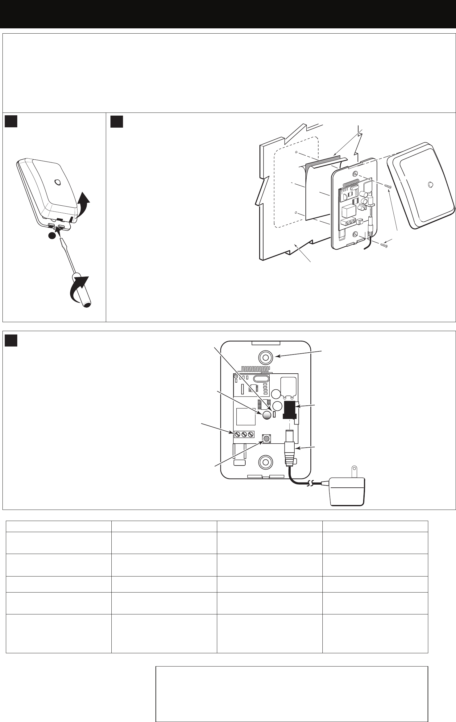
OPEN
OPEN – FR-C
OPEN – LA-ES
OPEN – LA-PT
5877-OPEN-V0
1
2
3
MOUNT
MOUNT – FR-C
MOUNT – LA-ES
MOUNT – LA-PT
• Use the double-sided tape (supplied) to mount the
sensor.
• Optional screws (supplied) are recommended.
• Use the double-sided tape (supplied) to mount the
sensor.
• Optional screws (supplied) are recommended.
• Use the double-sided tape (supplied) to mount the
sensor.
• Optional screws (supplied) are recommended.
• Use the double-sided tape (supplied) to mount the
sensor.
• Optional screws (supplied) are recommended.
NOTE: Mounting screws must be used in installations where temperatures drop to freezing 32° F (0° C).
NOTE: Mounting screws must be used in installations where temperatures drop to freezing 32° F (0° C).
NOTE: Mounting screws must be used in installations where temperatures drop to freezing 32° F (0° C).
NOTE: Mounting screws must be used in installations where temperatures drop to freezing 32° F (0° C).
PLUG IN 12VDC TRANSFORMER
PLUG IN 12VDC TRANSFORMER – FR-C
PLUG IN 12VDC TRANSFORMER – LA-ES
PLUG IN 12VDC TRANSFORMER – LA-PT
SPECIFICATIONS SPECIFICATIONS – FR-C SPECIFICATIONS - LA-ES SPECIFICATIONS –LS-PT
Electrical:
12VDC Power Supply; Operating Current 29-
31mA /
Electrical:
12VDC Power Supply; Operating Current 29-
31mA /
Electrical:
12VDC Power Supply; Operating Current 29-
31mA /
Electrical:
12VDC Power Supply; Operating Current 29-
31mA /
Environmental Conditions:
14° to 122° F (-10° to 50° C);
< 90% RH (non-condensing)
Environmental Conditions:
14° to 122° F (-10° to 50° C);
< 90% RH (non-condensing)
Environmental Conditions:
14° to 122° F (-10° to 50° C);
< 90% RH (non-condensing)
Environmental Conditions:
14° to 122° F (-10° to 50° C);
< 90% RH (non-condensing)
Frequency:
345 MHz
Frequency:
345 MHz
Frequency:
345 MHz
Frequency:
345 MHz
Dimensions:
4.5” H x 2.75” W x 0.25” D; (114.3mm x
69.85mm x 6.351mm)
Dimensions:
4.5” H x 2.75” W x 0.25” D; (114.3mm x
69.85mm x 6.351mm)
Dimensions:
4.5” H x 2.75” W x 0.25” D; (114.3mm x
69.85mm x 6.351mm)
Dimensions:
4.5” H x 2.75” W x 0.25” D; (114.3mm x
69.85mm x 6.351mm)
Compatibility:
Honeywell LYNX Series Controls, 5883H,
6160RF and 6150RF Keypads produced
after March 2007 (P/NSA6150RFAS-T3
Printed Circuit Board). 5800 series
Encrypted remotes not supported.
Compatibility:
Honeywell LYNX Series Controls, 5883H,
6160RF and 6150RF Keypads produced
after March 2007 (P/NSA6150RFAS-T3
Printed Circuit Board). 5800 series
Encrypted remotes not supported.
Compatibility:
Honeywell LYNX Series Controls, 5883H,
6160RF and 6150RF Keypads produced
after March 2007 (P/NSA6150RFAS-T3
Printed Circuit Board). ). 5800 series
Encrypted remotes not supported.
Compatibility:
Honeywell LYNX Series Controls, 5883H,
6160RF and 6150RF Keypads produced
after March 2007 (P/NSA6150RFAS-T3
Printed Circuit Board). ). 5800 series
Encrypted remotes not supported.
APPROVALS / LISTINGS
• FCC part 15, Class B verified
• IC, ICES-003, Class B verified
COMPLIANCE NOTES
Product must be tested at least once each year.
Product must be tested at least once each year.
Product must be tested at least once each year.
Product must be tested at least once each year.
REFER TO THE INSTALLATION INSTRUCTIONS FOR THE RECEIVER/CONTROL WITH WHICH THIS DEVICE IS
USED FOR DETAILS REGARDING LIMITATIONS OF THE ENTIRE ALARM SYSTEM.
<FR-C> REFER TO THE INSTALLATION INSTRUCTIONS FOR THE RECEIVER/CONTROL WITH WHICH THIS
DEVICE IS USED FOR DETAILS REGARDING LIMITATIONS OF THE ENTIRE ALARM SYSTEM.
<LA-ES> REFER TO THE INSTALLATION INSTRUCTIONS FOR THE RECEIVER/CONTROL WITH WHICH THIS
DEVICE IS USED FOR DETAILS REGARDING LIMITATIONS OF THE ENTIRE ALARM SYSTEM.
<LA-PT> REFER TO THE INSTALLATION INSTRUCTIONS FOR THE RECEIVER/CONTROL WITH WHICH THIS
DEVICE IS USED FOR DETAILS REGARDING LIMITATIONS OF THE ENTIRE ALARM SYSTEM.
5877-MOUNTING-V0
Mounting Screws
Mounting Screws
Mounting Screws
Mounting Screws
Double-sided Tape
Double-sided Tape
Double-sided Tape
Double-sided Tape
Mounting Surface
Mounting Surface
Mounting Surface
Mounting Surface
Relay Terminals
Relay Terminals
Relay Terminals
Relay Terminals
Mounting Holes (2)
Mounting Holes (2)
Mounting Holes (2)
Mounting Holes (2)
12 Vdc Power Supply Connector
12 Vdc Power Supply Connector
12 Vdc Power Supply Connector
12 Vdc Power Supply Connector
12 Vdc Power Supply Receptacle
12 Vdc Power Supply Receptacle
12 Vdc Power Supply Receptacle
12 Vdc Power Supply Receptacle
LED
LED
LED
LED
Program Button
Program Button
Program Button
Program Button
Jumper
Jumper
Jumper
Jumper
5877-PARTS-LBLD-V0
NO NC COM
1
2
3
5877 Relay Receiver / Relay Receiver / Relay Receiver / Relay Receiver
Installation Instructions / Instructions de montage (FRC) / Installation Instructions(LAES) / Installation Instructions (LAPT)
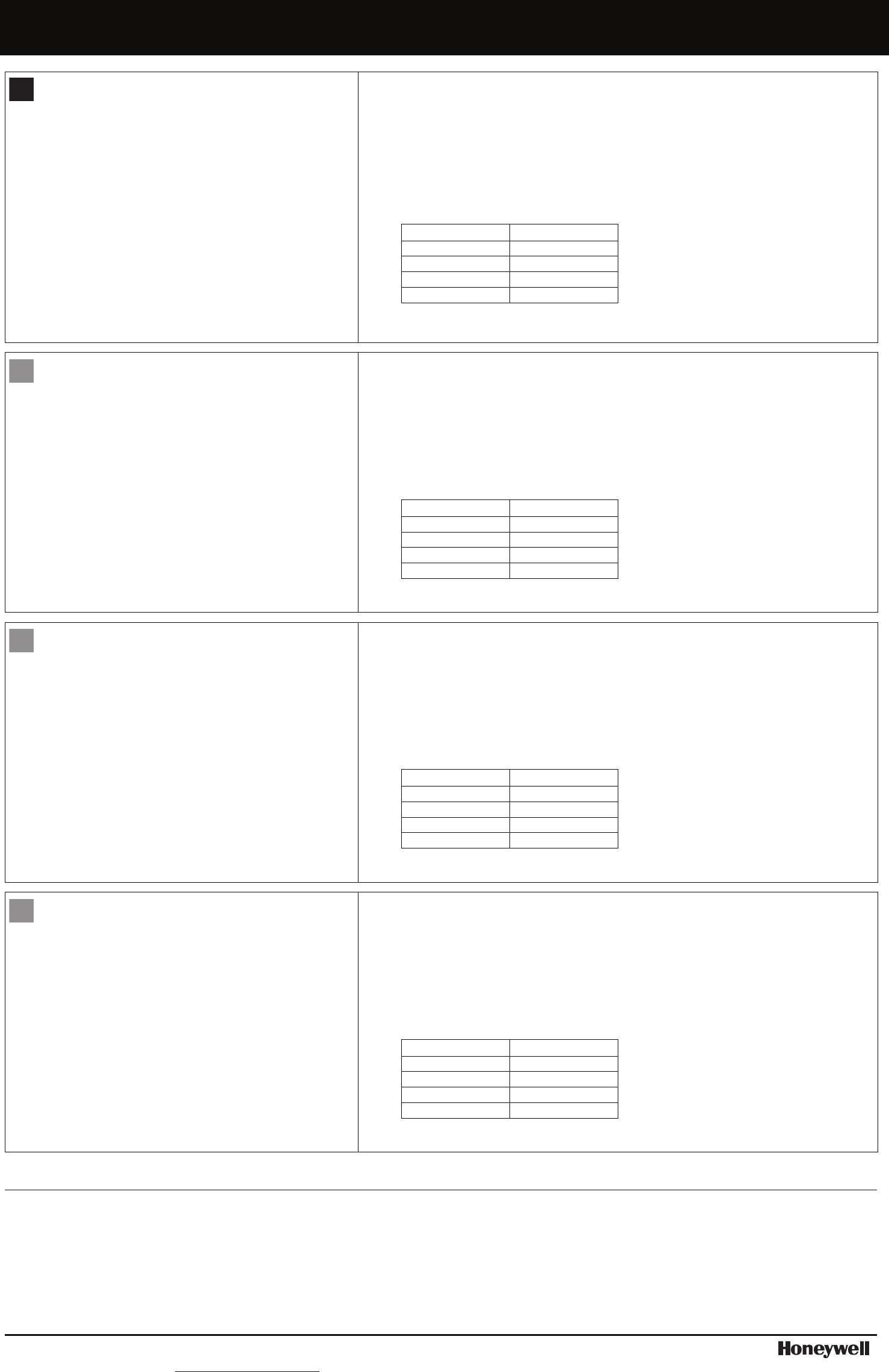
CONFIGURE THE 5877
TO USE WITH 5800 SERIES WIRELESS KEYS, ENROLL
WIRELESS KEYS INTO MODULE
1. Press (one second) and release the Program button; the LED
will start flashing GREEN.
2. Press the Wireless Key button to enroll it and the LED will stop
flashing GREEN. [Note: If no Wireless Key button is pushed,
the “enroll” program mode times out after 2 minutes.]
3. Repeat the process for each Wireless Key button; up to 7
buttons total.
4. Test by pressing each Wireless Key button enrolled in the relay
module; the relay module should click for each Wireless Key
button press.
TO DELETE ALL WIRELESS KEY BUTTONS
Press and continue to hold the Program button; the LED turns
RED, then turns off, then RED again; release the Program button.
This takes about 15 seconds.
TO USE FOR SYSTEM STATUS [Optional] ENROLL RF HOUSE ID CODE INTO MODULE
NOTE: The System Control Panel must be capable of transmitting system status, for example, an
L5000, L3000, or a VISTA Panel with a 5883 transceiver. Ensure the House ID is enabled in the
panel programming.
1. Press (one second) and release the Program button; the LED will start flashing GREEN.
2. IMMEDIATELY press (one second) and release the Program button again. The LED will start
flashing ORANGE.
3. Disarm or Arm the control panel. The LED stops flashing ORANGE and then shows the status of
the control panel (see LED indications).
[Note: If no House ID code is enrolled, the enroll program mode times out after 2 minutes.]
LED STATUS INDICATION
Flashing RED Armed AWAY
Solid RED Armed STAY
Solid GREEN System READY
Flashing ORANGE ALARM / Panic
4. Test the status by arming and disarming the system in both AWAY and STAY Modes.
CONFIGURE THE 5877 – FR-Can
TO USE WITH 5800 SERIES WIRELESS KEYS, ENROLL
WIRELESS KEYS INTO MODULE
1. Press (one second) and release the Program button; the LED
will start flashing GREEN.
2. Press the Wireless Key button to enroll it and the LED will stop
flashing GREEN. [Note: If no Wireless Key button is pushed,
the “enroll” program mode times out after 2 minutes.]
3. Repeat the process for each Wireless Key button; up to 7
buttons total.
4. Test by pressing each Wireless Key button enrolled in the relay
module; the relay module should click for each Wireless Key
button press.
TO DELETE ALL WIRELESS KEY BUTTONS
Press and continue to hold the Program button; the LED turns
RED, then turns off, then RED again; release the Program button.
This takes about 15 seconds.
TO USE FOR SYSTEM STATUS [Optional] ENROLL RF HOUSE ID CODE INTO MODULE
NOTE: The System Control Panel must be capable of transmitting system status, for example, an
L5000, L3000, or a VISTA Panel with a 5883 transceiver. Ensure the House ID is enabled in the
panel programming.
1. Press (one second) and release the Program button; the LED will start flashing GREEN.
2. IMMEDIATELY press (one second) and release the Program button again. The LED will start
flashing ORANGE.
3. Disarm or Arm the control panel. The LED stops flashing ORANGE and then shows the status of
the control panel (see LED indications).
[Note: If no House ID code is enrolled, the enroll program mode times out after 2 minutes.]
LED STATUS INDICATION
Flashing RED Armed AWAY
Solid RED Armed STAY
Solid GREEN System READY
Flashing ORANGE ALARM / Panic
4. Test the status by arming and disarming the system in both AWAY and STAY Modes.
CONFIGURE THE 5877 – LA-ES
TO USE WITH 5800 SERIES WIRELESS KEYS, ENROLL
WIRELESS KEYS INTO MODULE
1. Press (one second) and release the Program button; the LED
will start flashing GREEN.
2. Press the Wireless Key button to enroll it and the LED will stop
flashing GREEN. [Note: If no Wireless Key button is pushed,
the “enroll” program mode times out after 2 minutes.]
3. Repeat the process for each Wireless Key button; up to 7
buttons total.
4. Test by pressing each Wireless Key button enrolled in the relay
module; the relay module should click for each Wireless Key
button press.
TO DELETE ALL WIRELESS KEY BUTTONS
Press and continue to hold the Program button; the LED turns
RED, then turns off, then RED again; release the Program button.
This takes about 15 seconds.
TO USE FOR SYSTEM STATUS [Optional] ENROLL RF HOUSE ID CODE INTO MODULE
NOTE: The System Control Panel must be capable of transmitting system status, for example, an
L5000, L3000, or a VISTA Panel with a 5883 transceiver. Ensure the House ID is enabled in the
panel programming.
1. Press (one second) and release the Program button; the LED will start flashing GREEN.
2. IMMEDIATELY press (one second) and release the Program button again. The LED will start
flashing ORANGE.
3. Disarm or Arm the control panel. The LED stops flashing ORANGE and then shows the status of
the control panel (see LED indications).
[Note: If no House ID code is enrolled, the enroll program mode times out after 2 minutes.]
LED STATUS INDICATION
Flashing RED Armed AWAY
Solid RED Armed STAY
Solid GREEN System READY
Flashing ORANGE ALARM / Panic
4. Test the status by arming and disarming the system in both AWAY and STAY Modes.
CONFIGURE THE 5877 – LA-PT
TO USE WITH 5800 SERIES WIRELESS KEYS, ENROLL
WIRELESS KEYS INTO MODULE
1. Press (one second) and release the Program button; the LED
will start flashing GREEN.
2. Press the Wireless Key button to enroll it and the LED will stop
flashing GREEN. [Note: If no Wireless Key button is pushed,
the “enroll” program mode times out after 2 minutes.]
3. Repeat the process for each Wireless Key button; up to 7
buttons total.
4. Test by pressing each Wireless Key button enrolled in the relay
module; the relay module should click for each Wireless Key
button press.
TO DELETE ALL WIRELESS KEY BUTTONS
Press and continue to hold the Program button; the LED turns
RED, then turns off, then RED again; release the Program button.
This takes about 15 seconds.
TO USE FOR SYSTEM STATUS [Optional] ENROLL RF HOUSE ID CODE INTO MODULE
NOTE: The System Control Panel must be capable of transmitting system status, for example, an
L5000, L3000, or a VISTA Panel with a 5883 transceiver. Ensure the House ID is enabled in the
panel programming.
1. Press (one second) and release the Program button; the LED will start flashing GREEN.
2. IMMEDIATELY press (one second) and release the Program button again. The LED will start
flashing ORANGE.
3. Disarm or Arm the control panel. The LED stops flashing ORANGE and then shows the status of
the control panel (see LED indications).
[Note: If no House ID code is enrolled, the enroll program mode times out after 2 minutes.]
LED STATUS INDICATION
Flashing RED Armed AWAY
Solid RED Armed STAY
Solid GREEN System READY
Flashing ORANGE ALARM / Panic
4. Test the status by arming and disarming the system in both AWAY and STAY Modes.
FEDERAL COMMUNICATIONS COMMISSION STATEMENT:
The user shall not make any changes or modifications to the equipment unless authorized by the Installation Instructions or User Manual. Unauthorized changes or
modifications could void the user's authority to operate the equipment.
CLASS B DIGITAL DEVICE STATEMENT
This equipment has been tested to FCC requirements and has been found acceptable for use. The FCC requires the following statement for your information:
This equipment generates and uses radio frequency energy and if not installed and used properly, that is, in strict accordance with the manufacturer's instructions, may
cause interference to radio and television reception. It has been type tested and found to comply with the limits for a Class B computing device in accordance with the
specifications in Part 15 of FCC Rules, which are designed to provide reasonable protection against such interference in a residential installation. However, there is no
guarantee that interference will not occur in a particular installation. If this equipment does cause interference to radio or television reception, which can be
determined by turning the equipment off and on, the user is encouraged to try to correct the interference by one or more of the following measures:
• If using an indoor antenna, have a quality outdoor antenna installed.
• Reorient the receiving antenna until interference is reduced or eliminated.
• Move the radio or television receiver away from the receiver/control.
• Move the antenna leads away from any wire runs to the receiver/control.
• Plug the receiver/control into a different outlet so that it and the radio or television receiver are on different branch circuits.
• Consult the dealer or an experienced radio/TV technician for help.
FCC / IC STATEMENT:
This device complies with Part 15 of the FCC Rules and Industry Canada license-exempt RSS standard(s). Operation is
subject to the following two conditions: (1) This device may not cause harmful interference (2) This device must accept
any interference received, including interference that may cause undesired operation.
Cet appareil est conforme à la partie 15 des règles de la FCC et exempt de licence de norme(s) RSS d’Industrie Canada.
Son fonctionnement est soumis aux conditions suivantes: (1) Cet appareil ne doit pas causer d’interférences nuisibles.
(2) Cet appareil doit accepter toute interférence reçue y compris les interférences causant une réception indésirable.
Honeywell is a registered trademark of Honeywell International Inc. All other trademarks are the
properties of their respective owners. All rights reserved. Made in Taiwan.
For the latest U.S. warranty information, please visit: www.honeywell.com/security/hsc/resources/wa or
Please contact your local authorized Honeywell representative for product warranty information.
Ê800-10947XŠ
P/N 800-10947 Rev A 3/12
2 Corporate Center Drive, Suite 100
P.O. Box 9040, Melville, NY 11747
Copyright © 2012 Honeywell International Inc.
www.hone
y
well.com/securit
y
To Disable the
LED, remove the
Jumper next to
the LED.
To Disable the
LED, remove the
Jumper next to
the LED.
To Disable the
LED, remove the
Jumper next to
the LED.
To Disable the
LED, remove the
Jumper next to
the LED.
4
4
4
4