Ademco 8DL5800SS2 Wireless Shock Sensor User Manual K0011V1
Honeywell International Inc. Wireless Shock Sensor K0011V1
Ademco >
Users Manual
GENERAL INFORMATION
The 5800SS1 is a wireless shock sensor
intended for use in systems that support 5800
series devices. Each transmitter has its own
unique serial number, assigned during
manufacture, which must be “enrolled” in the
control panel before the device can be used
with the system. Refer to the control panel's
Installation and Setup Guide for programming
details.
One 5800SS1 is required for each pane of
glass protected. (Do not use more than one
sensor per pane.)
Types of Glass Protection
• Tempered
• Ordinary Plate
• Laminated Type
• Wired
• Coated*
• Sealed Insulated
* Not for use in UL installations.
Note: It is not necessary to remove the case
cover during installation.
ENROLLING THE 5800SS1
You must enroll the 5800SS1 serial number
in the control panel during zone
programming. The control panel's Installation
and Setup Guide provides detailed
programming procedures. Before
programming, perform the following:
1. To cause the transmitter to transmit,
remove the “PULL TO CONNECT
BATTERY” tab (see Figure 1). (For
additional transmissions, lightly tap on
the base of the sensor with a
screwdriver.)
5800SS1-001-V0
PULL
TAB
SENSOR
Figure 1
2. When programming the shock
sensor, note the following:
• Input Type = 3 (Supervised RF)
• Loop Number = 1
3. When prompted for the serial number,
you can transmit by lightly tapping on
the base of the sensor with a
screwdriver or by manually entering
the serial and loop number.
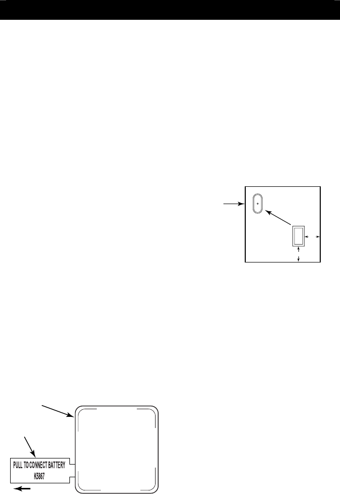
MOUNTING
1. Determine the optimum mounting
location. For best sensitivity, the
sensor should be mounted one-inch
from the corner edge of the window
frame (see Figure 2).
1in.
1in.
10 FT. RADIUS
MAXIMUM
COVERAGE
STRIKE AT
FURTHEST
OPPOSITE
CORNER WITH
SCREWDRIVER
HANDLE
MOUNT 1 INCH FROM CORNER
OF WINDOW FRAME.
5800SS1-003-V0
Figure 2
2. Before the transmitter is permanently
mounted, conduct Go/No Go tests (see
control’s instructions) to verify adequate
signal strength from the mounting
location.
3. Always verify range by holding the
sensor in the approximate mounting
location and tapping at the base. The
panel (in test mode) should respond to
the transmissions. If not, find a more
suitable mounting location.
4. Clean the glass, where the sensor will be
mounted, with a mixture of water and
isopropyl alcohol.
5. Once the glass has dried, remove the
tape backing paper and firmly press the
sensor in the desired mounting location.
6. Verify operation by striking the furthest
opposite corner of the glass with the
handle of a large screwdriver. Always
check the alarm panel keypad to verify
that the zone has tripped.
7. Apply optional “WARNING” label to the
outside glass surface opposite the tape
side of the 5800SS1.
5800SS1
5800SS1 5800SS1
5800SS1
Wireless Shock Sensor
Wireless Shock Sensor Wireless Shock Sensor
Wireless Shock Sensor -
--
-
Installation Guide
FCC / IC STATEMENTS ARE IN THE MIDDLE OF PAGE 2
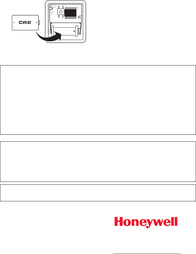
REPLACING THE BATTERY
1. Using a screwdriver, carefully remove
the sensor’s cover.
2. Check the battery polarity orientation
before installing (see Figure 3).
3. Insert the battery securely in the sensor.
4. Snap the sensor cover back in place.
5800SS1-001-V0
Figure 3
SPECIFICATIONS
Glass Coverage:
Plate, Laminate, Wired, Sealed Insulated,
Coated* and Tempered glass, with thick-
nesses between 3/32” (2.38mm) and 1/4”
(6.35mm) and up to 10 ft (3.048m) distance
from mounting location. One sensor is
required for each separate pane of glass.
* Not for use in UL installations.
Dimensions:
1.6" H x 1.6" W x 0.8" D (40.64 mm x 40.64
mm x 20.32 mm)
Power:
Single 3V Panasonic CR2, or Duracell
DLCR2 Lithium Battery
WARNING
Risk of fire, explosion, and burns. Do not
recharge, disassemble, heat above 212º F
(100º C) or incinerate. Dispose of used
batteries properly. Keep away from children.
FCC / IC STATEMENT
This device complies with Part 15 of the FCC Rules, and RSS 210 of IC. Operation is subject to
the following two conditions: (1) This device may not cause harmful interference (2) This device
must accept any interference received, including interference that may cause undesired
operation.
Cet appareil est conforme à la partie 15 des règles de la FCC & de RSS 210 des Industries
Canada. Son fonctionnement est soumis aux conditions suivantes: (1) Cet appareil ne doit pas
causer d' interferences nuisibles. (2) Cet appareil doit accepter toute interference reçue y compris
les interferences causant une reception indésirable.
FEDERAL COMMUNICATIONS COMMISSION STATEMENTS
The user shall not make any changes or modifications to the equipment unless authorized by the
Installation Instructions or User's Manual. Unauthorized changes or modifications could void the
user's authority to operate the equipment.
TO THE INSTALLER
Regular maintenance and inspection (at least annually) by the installer and frequent testing by
the user are vital to continuous satisfactory operation of any alarm system.
The installer should assume the responsibility of developing and offering a regular maintenance
program to the user as well as acquainting the user with the proper operation and limitations of
the alarm system and its component parts. Recommendations must be included for a specific
program of frequent testing (at least weekly) to ensure the system’s proper operation at all times.
FOR WARRANTY INFORMATION AND DETAILS REGARDING THE LIMITATIONS OF THE
ENTIRE ALARM SYSTEM REFER TO THE INSTALLATION INSTRUCTIONS FOR THE
RECEIVER/CONTROL USED WITH THIS DEVICE.
ÊK0011V1†Š
K0011V1 1/12 Rev. A
2 Corporate Center Drive, Suite 100
P.O. Box 9040, Melville, NY 11747
Copyright 2011 Honeywell International Inc.
http://www.honeywell.com/security