Ademco 8DL5800STAT Security accessory User Manual II with FCC part 15 statements
Honeywell International Inc. Security accessory II with FCC part 15 statements
UserManual.wiki
>
Ademco
>
8DL5800STAT User Manual
II with FCC part 15 statements
Navigation menu
Upload a User Manual
Namespaces
Wiki Guide
HTML
PDF
Info
Views
User Manual
Discussion / Help
Navigation
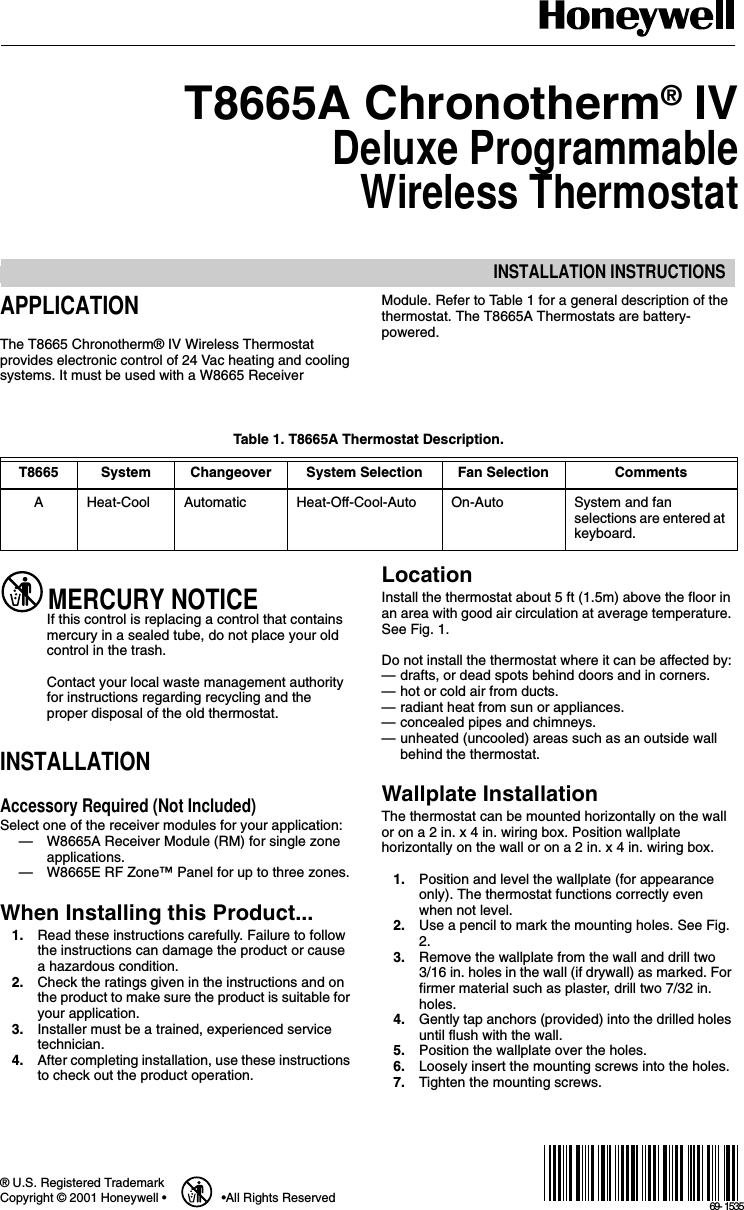
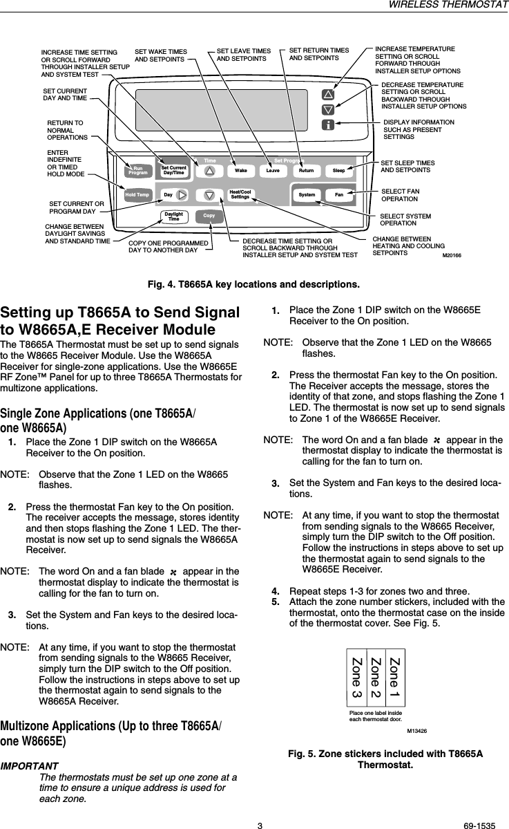
![WIRELESS THERMOSTAT69-1535 2Fig. 1. Typical thermostat location.Fig. 2. Mounting the wallplate.Mounting Thermostat1. Engage tabs at the top of the thermostat and wall-plate. See Fig. 3.2. Press lower edge of case to close and latch.NOTE: To remove the thermostat from the wall, first pull out at the bottom of the thermostat; remove top last.Fig. 3. Mounting thermostat on wallplate.Using Thermostat KeysThe thermostat keys are used to:•set current day and time.•program times and setpoints for heating and cooling.•temporarily override program temperatures•display present setting,•configure Installer Setup, •check self-test,•set the system operation, •set the fan operation. See Fig. 4 for key locations.5 FEET[1.5 METERS]YESNONONOM10106WIRES THROUGH WALLWALLMOUNTING HOLESM15044MOUNTING SCREWSWALLANCHORS(2)M14628PRESS LOWER EDGE OF CASE TO LATCH.ENGAGE TABS AT TOP OF THERMOSTAT AND WALLPLATE.A.B.](https://usermanual.wiki/Ademco/8DL5800STAT/User-Guide-166225-Page-2.png)