Ademco 8DL5800TSTAT Security device accessory User Manual 69 1534 W8665A E FR Receiver Module
Honeywell International Inc. Security device accessory 69 1534 W8665A E FR Receiver Module
Ademco >
II with FCC PART 15 statements
® U.S. Registered Trademark
Copyright © 2001 Honeywell • •All Rights Reserved
INSTALLATION INSTRUCTIONS
69- 1534- 1
W8665A,E
RF Receiver Module
APPLICATION
The W8665A,E RF Receiver Module (RM) provides
24 Vac control of HVAC equipment when used with a
T8665A Chronotherm® IV Wireless Programmable
Thermostat. The W8665A can be used with 1H/1C
single-zone conventional applications. The W8665E can
be used with up to three zones when used with a
Honeywell EMM-3 Electronic MiniZone© Panel or TZ-3
TotalZone™ Panel. See Table 1.
INSTALLATION
CAUTION
Equipment Damage Hazard.
Do not mount W8665 inside HVAC equipment.
Mount only on wall.
1. Mount the thermostats in each zone of the living
space using the installation instructions provided
with each thermostat.
2. Mount the dampers in the ductwork using the
installation instructions provided with each damper.
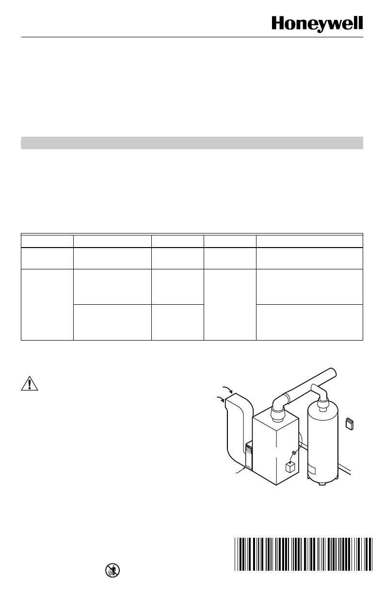
3. Mount the W8665 RF Receiver Module near the
HVAC equipment on a wall. See Fig. 1.
4. Level the W8665 for appearance only.
Fig. 1. W8665 mounting location.
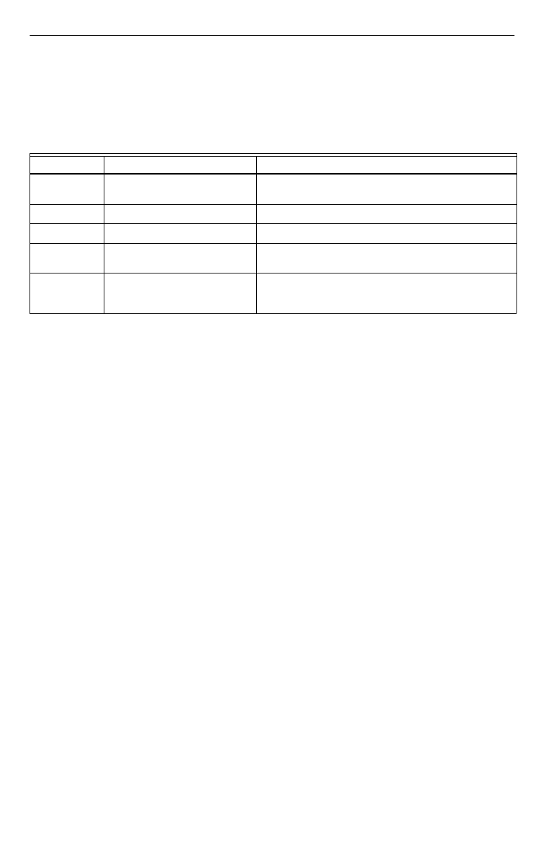
Table 1. W8665 Description.
Model Application Stages Zones Comments
W8665A Conventional gas, oil or
electric systems. 1H/1C One Use with T8665A Wireless
Thermostat.
W8665E Conventional gas, oil or
electric systems. 1H/1C Up to three Use with T8665A Wireless
Thermostats.
Use with EMM-3 Electronic
MiniZone™ Panel
Single or multi-stage
conventional or heat
pump systems.
1H/1C or up to
3H/2C Use with T8665A Wireless
Thermostats.
Use with TZ-3 TotalZone™ Zone
Control Panel.
M20162
WATER
HEATER
W8665
ELECTRONIC AIR CLEANER
RETURN
AIR
FURNACE
OR BOILER
HIGH
EFFICIENCY
AIR CLEANER
W8665A,E RF RECEIVER MODULE
69-1534-1 2
WIRING
All wiring must comply with local electric codes and
ordinances. See Fig. 2-4 wiring diagrams for specific
applications. Refer to Tables 2 and 3 for terminal
designations.
CAUTION
Voltage Hazard.
Can cause electrical shock or equipment
damage.
Disconnect power before beginning installation.
Wiring the W8665A
Connect the RF Receiver Module to the equipment
loads. See Fig. 2 and Table 2.
Wiring the W8665E
Connect the RF Receiver Module zones to the
appropriate thermostat zone connections on the EMM-3
MiniZone™ Panel or TZ-3 TotalZone ™ Zone Control
Panel. See Fig. 3 or 4 and Table 3.
Table 2. W8665A Terminal Designations.
Terminal
Designation Function
R 24 Vac transformer hot.
Powers RF receiver module.
C 24 Vac transformer common.
Powers RF receiver module.
RZ 24 Vac system transformer.
Not used in single zone
applications.
Y Stage 1 cool.
W Stage 1 heat.
G Fan.
Table 3. W8665E Terminal Designations.
Terminal
Designation Function
R 24 Vac transformer hot.
Powers RF receiver module.
C 24 Vac transformer common.
Powers RF receiver module.
RZ 24 Vac system transformer.
Connect to R of Zone1 thermostat
on zone panel.
RZ 24 Vac system transformer.
Connect to R of Zone 2 thermostat
on zone panel.
RZ 24 Vac system transformer.
Connect to R of Zone 3 thermostat
on zone panel.
Zone 1 Y Stage 1 cool.
Zone 1 W Stage 1 heat.
Zone 1 G Fan.
Zone 2 Y Stage 1 cool.
Zone 2 W Stage 1 heat.
Zone 2 G Fan
Zone 3 Y Stage 1 cool.
Zone 3 W Stage 1 heat.
Zone 3 G Fan
W8665A,E RF RECEIVER MODULE
3 69-1534-1
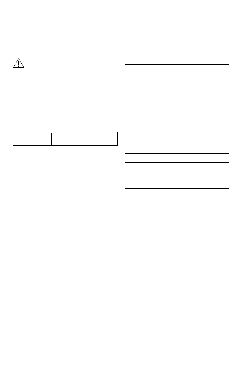
Fig. 2. Connecting the W8665A RF Receiver Module to the equipment.
M20163
COMM
T8665A
THERMOSTAT
ZONE 1 W8665A
LED LED
LED STATES:
COMM:
RAPIDLY FLASHING GREEN — RECEIVING INFORMATION FROM THERMOSTAT.
GREEN OFF — STANDBY, READY TO RECEIVE INFORMATION.
ZONE:
RED ON — SYSTEM (HEAT, COOL OR FAN) IS ON.
RED OFF — SYSTEM (HEAT, COOL OR FAN) IS OFF.
FLASHING RED — ERROR. NOT RECEIVING SIGNAL FROM THERMOSTAT.
RAPIDLY FLASHING RED — RECEIVER IN SET-UP MODE.
DIP SWITCH SETTINGS:
OFF: NOT SET-UP TO RECEIVE INFORMATION FROM A THERMOSTAT.
ON: READY TO RECEIVE INFORMATION FROM THERMOSTAT AFTER
SET-UP IS COMPLETE.
SET-UP:
MOVE DIP SWITCH TO ON POSITION AND MAKE THERMOSTAT CALL FOR FAN.
NOTE: ALL OTHER THERMOSTATS MUST BE OFF (NOT CALLING) DURING SET-UP.
ZONE 1
ZONE 2
ZONE 3
ON
HEAT
RELAY
COOL
RELAY
FAN
RELAY
L2
L1 (HOT)
YWG
ZONE 1
RCRZ
W8665A,E RF RECEIVER MODULE
69-1534-1 4
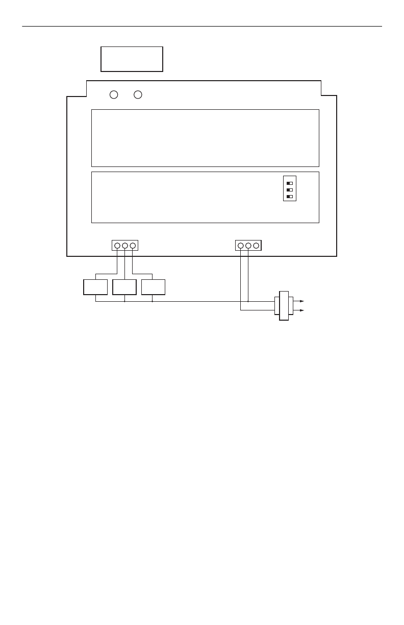
Fig. 3. Connecting the W8665E RF Zone™ Panel to the EMM-3 MiniZone™ Panel to control 1H/1C with up three
thermostat zone connections.
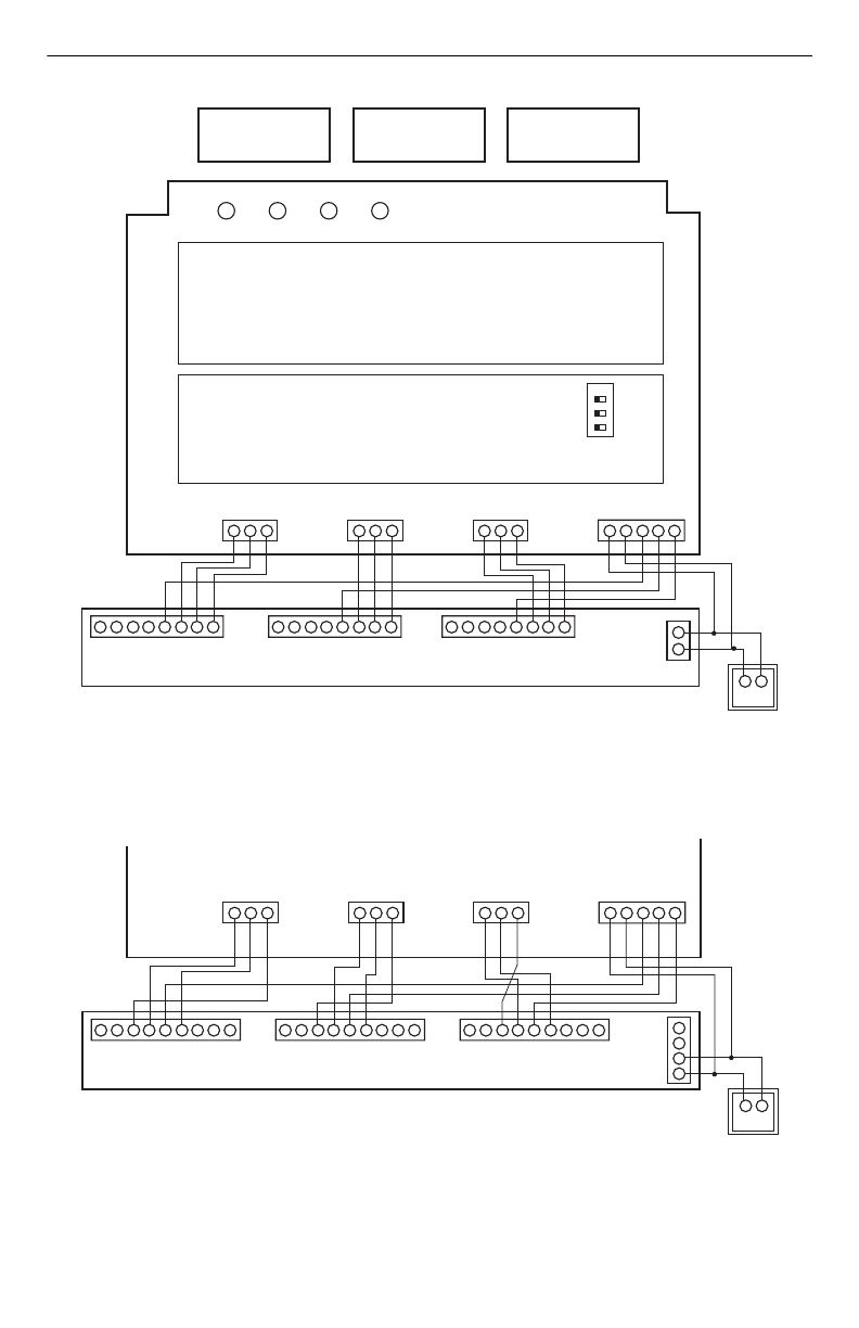
Fig. 4. Connecting the W8665E RF Zone™ Panel to the TZ-3 TotalZone™Zone Control Panel to operate up to
3H/2C with up to three thermostat zone connections.
M20164
R
R
C
C
COMM
T8665A
ZONE 1
THERMOSTAT
ZONE 1 ZONE 2 W8665E
LED LED LEDLED
ZONE 3
YWG
M1 M4 M6 C R Y W G
ZONE 1
EMM-3
LED STATES:
COMM:
RAPIDLY FLASHING GREEN — RECEIVING INFORMATION FROM THERMOSTAT.
GREEN OFF — STANDBY, READY TO RECEIVE INFORMATION.
ZONE:
RED ON — SYSTEM (HEAT, COOL OR FAN) IS ON.
RED OFF — SYSTEM (HEAT, COOL OR FAN) IS OFF.
FLASHING RED — ERROR. NOT RECEIVING SIGNAL FROM THERMOSTAT.
RAPIDLY FLASHING RED — RECEIVER IN SET-UP MODE.
YWG
ZONE 2
YWG
ZONE 3
24V, 40 VA TRANSFORMER
R C RZ RZ RZ
M1 M4 M6 C R Y W G M1 M4 M6 C R Y W G
DIP SWITCH SETTINGS:
OFF: NOT SET-UP TO RECEIVE INFORMATION FROM A THERMOSTAT.
ON: READY TO RECEIVE INFORMATION FROM THERMOSTAT AFTER
SET-UP IS COMPLETE.
SET-UP:
MOVE DIP SWITCH TO ON POSITION AND MAKE THERMOSTAT CALL FOR FAN.
NOTE: ALL OTHER THERMOSTATS MUST BE OFF (NOT CALLING) DURING SET-UP.
ZONE 1
ZONE 2
ZONE 3
ON
T8665A
ZONE 2
THERMOSTAT
T8665A
ZONE 3
THERMOSTAT
OC
OC
TR2
TR1
CR
M20165
W8665E
YWG
W2 L G Y R W M6M4M1
ZONE 1
TZ-3
YWG
ZONE 2
YWG
ZONE 3
24V, 40 VA TRANSFORMER
R C RZ RZ RZ
W2 L G Y R W M6M4M1 W2 L G Y R W M6M4M1

W8665A,E RF RECEIVER MODULE
5 69-1534-1
SETUP
Setting Up W8665A,E to Receive Signals
from the T8665A Thermostat(s)
The T8665A Thermostat(s) require(s) setup to send
signals to the W8665 Receiver Module to operate:
• The W8665A Receiver is used for single-zone
applications.
• The W8665E RF Zone™ Panel is used for up to three
T8665A Thermostats for multi-zone applications.
IMPORTANT
Be sure the thermostat is at least five feet away
from the W8665 during setup.
Single Zone Applications (1 W8665A/1 T8665A)
1. Power up the W8665A and install the batteries in
the T8665A Thermostat.
2. Place the W8665A Zone 1 DIP switch to the On
position.
NOTE: The W8665A Zone 1 LED will flash.
3. Press the thermostat Fan On key:
a. The receiver accepts the message and stores
the identity.
b. The zone 1 LED stops flashing.
c. The thermostat is now set to send signals to
the W866A Receiver.
NOTE: The word, On, and a fan blade appear in the
thermostat display to indicate the thermostat is
calling for the fan to turn on.
d. Use Fan key to turn off fan.
4. Set System and Fan keys to the desired locations.
NOTE: At any time, if you want to stop the thermostat
from sending signals to the W8665 Receiver,
turn the DIP switch to Off. Then repeat steps 1-
3 to set up the thermostat to send signals to the
W8665 Receiver.
Multizone Applications (1 W8665E/Up to 3
T8665A)
1. Power up the W8665 and install the batteries in the
T8665 Thermostats.
2. Set the thermostats so no zones are calling for sys-
tem or fan.
3. Set up each zone separately to ensure that a
unique address is used for each zone.
4. Place the zone 1 DIP switch on the W8665E
Receiver to the On position.
NOTE: The W8665E zone 1 LED will flash.
5. Press the thermostat Fan On key:
a. The receiver accepts the message and stores
the zone identity.
b. The zone 1 LED stops flashing.
c. The thermostat is now set to send signals to
the W8665E Receiver.
NOTE: The word, On, and a fan blade appear in the
thermostat display to indicate the thermostat is
calling for the fan to turn on.
d. Use Fan key to turn off fan.
NOTE: At any time, if you want to stop the thermostat
from sending signals to the W8665 Receiver,
turn the DIP switch to Off. Then repeat steps 4
and 5 to set up the thermostat to send signals to
the W8665 Receiver.
6. Repeat steps 4 and 5 for zones two and three.
7. Set System and Fan keys to desired locations.
8. Attach the zone number sticker, included with the
thermostat, onto the thermostat case on the inside
of the thermostat cover. See Fig. 5.
Fig. 5. Zone number stickers for inside of thermostat
cover.
OPERATION
W8665A Sequence of Operation
On a call for heating or cooling, the thermostat sends a
signal to the W8665A to bring on the heating or cooling
until the call is satisfied. The Comm LED flashes when
the W8665A receives a signal from the thermostat to turn
on the system or approximately every ten minutes as a
status update. On a call for heating, cooling or fan, the
zone LED lights red.
W8665E Sequence of Operation
On a call for heating or cooling from any zone, the
thermostat sends a signal to the W8665E to bring on the
heating or cooling in that zone until the call is satisfied.
The Comm LED flashes when the W8665E receives a
signal from the thermostat in any zone to turn on the
system or approximately every ten minutes as a status
update. On a call for heating, cooling or fan, the zone
LED lights red.
W8665E Single and Multi-Stage
Operation
The first stage is energized by the thermostat.
To control multistage conventional and heat pump
systems, the W8665 must be wired to a zone control
panel that is able to control multiple stages of heat and/or
cool (such as the TZ-3 TotalZone™ Zone Control Panel).
The zone panel (not the RF panel) controls these stages
based on the number of zones calling or with a timer. See
the Zone Control Panel Instructions for more details on
how to control up to three stages of heat and two stages
of cool.
Place one label inside
each thermostat door.
Zone 1
Zone 2
Zone 3
M13426
W8665A,E RF RECEIVER MODULE
69-1534-1 6
LED Operation (See Table 4)
NOTE: See Setting up W8665A,E Receiver Module to
Receive Signals from the T8665A Thermostat
section.
Table 4. LED Operation.
LED LED action Meaning
Comm Flashes rapidly for 2-3 seconds. Indicates device is currently receiving information from the
T8665 Thermostat.
Zones 1-3 On constantly. Indicates system (heat, cool, or fan) is on.
Zones 1-3 Off constantly. Indicates system (heat, cool, or fan) is off.
Zones 1-3 Flashes rapidly until signal is
received. Indicates zone is being set up to receive signals from a
transmitter (T8665 Thermostat).
Zones 1-3 Flashes continuously. Indicates a problem receiving signals from the transmitter
(T8665 Thermostat). See Troubleshooting Guide for more
information.
W8665A,E RF RECEIVER MODULE
7 69-1534-1
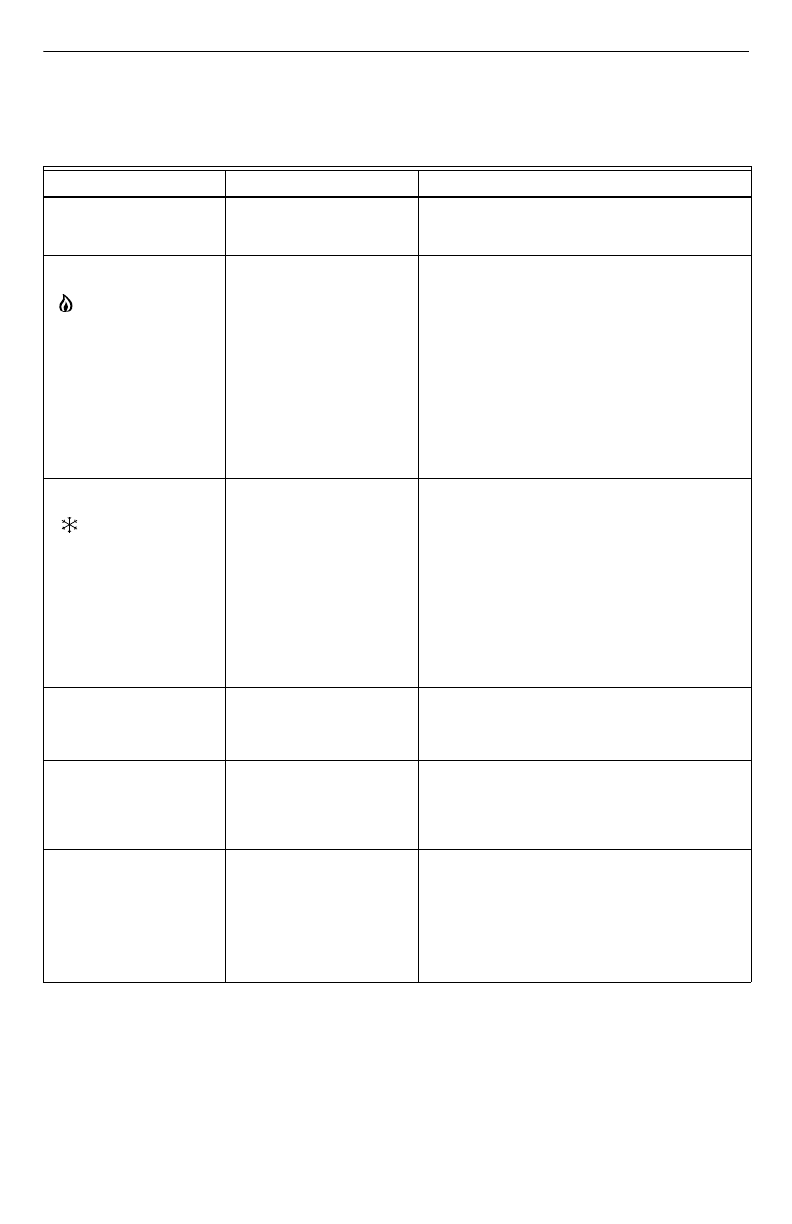
TROUBLESHOOTING (TABLE 5)
Table 5. Troubleshooting Guide.
Symptom Possible Cause Action
Display does not come on. Thermostat is not being
powered. Check if batteries are present and installed correctly.
•If batteries are in and installed correctly, replace
thermostat.
Heating does not come on.
System on indicator
( = heat) is showing in
display.
Communication is not being
completed.
Heating load at W8665 is not
connected correctly.
End and repeat the call for heat.
Check the Comm LED and Zone LED on the W8665
while the call is being made.
•If the Comm LED does not flash when thermostat
first calls for equipment, turn that zone DIP switch
to Off. Refer to Setup section to reset the W8665.
•If the Zone LED flashes continuously, turn that
zone DIP switch to Off. Refer to Setup section to
reset the W8665.
•Check if 24 Vac is present:
•Check between R and C on W8665.
•Check between W of troubled zone and C on
W8665.
If voltage is present, troubleshoot heating system.
Cooling does not come on.
System on indicator
( = cool) is showing in
display.
Communication is not being
completed.
Cooling load at W8665 is not
connected correctly.
End and repeat the call for cool.
Wait five minutes for the compressor delay to end.
•If the Comm LED does not flash when thermostat
first calls for equipment, turn that zone DIP switch
to Off. Refer to Setup section to reset the W8665.
•If the Zone LED flashes continuously, turn that
zone DIP switch to Off.Refer to Setup section to
reset the W8665.
•Check if 24 Vac is present:
•Check between R and C on W8665.
•Check between Y of troubled zone and C on
W8665.
If voltage is present, troubleshoot cooling system.
Wait is displayed and the
call for cool has not started. Compressor protection is in
effect. Compressor protection can be set on the T8665A
from 0 to 5 minutes to prevent compressor damage
due to rapid cycling.
Wait until the compressor protection period expires.
2nd stage heat or cool (or
3rd stage heat) does not
energize.
W8665 is not wired to a TZ-3
TotalZone™ Zone Control
Panel that controls the
multiple heat and cool
stages.
Wire W8665 to TZ-3 TotalZone™ Zone Control
Panel to control multi-stage systems.
Check TZ-3 TotalZone™ Zone Control Panel and set
correctly.
Fan does not come on with
a call for electric heat. Electric heat setting is not
configured.
Fan load at W8665 is not
connected correctly.
Set thermostat Installer Setup Number 2 to 1 for
electric heat. See thermostat instructions for details.
Check that 24 Vac is present between R and C.
Check that 24 Vac is present between G and C.
If voltage is present, troubleshoot system.

69-1534-1 G.H. 09-01 www.honeywell.com/yourhome
W8665A,E RF RECEIVER MODULE
Printed in U.S.A. on recycled
paper containing at least 10%
post-consumer paper fibers.
Home and Building Control Home and Building Control
Honeywell Honeywell Limited-Honeywell Limitée
1985 Douglas Drive North 35 Dynamic Drive
Golden Valley, MN 55422 Scarborough, Ontario
M1V 4Z9
FCCID: CFS8DL5800TSTAT
This device complies with Part 15 of the FCC Rules. Operation is subject to the following two conditions:
(1) This device may not cause harmful interference, and
(2) This device must accept any interference received, including interference that may cause undesired operation.
FEDERAL COMMUNICATIONS COMMISSION (FCC) STATEMENT
This equipment has been tested to FCC requirements and has been found acceptable for use. The FCC requires the
following statement for your information:
This equipment generates and uses radio frequency energy and, if not installed and used properly; that is, in strict
accordance wih the manufacturer’s instructions, may cause interference to radio and television reception. It has been
type tested and found to comply with the limits for a Class B computing device in accordance with the specifications in
Part 15 of FCC Rules, which are designed to provide reasonable protection against such interference in a residential
installation. However, there is no guarantee that interference will not occur in a particular installation. If this equipment
does cause interference to radio or television reception, which can be determined by turning the equipment off and on,
the user is encouraged to try to correct the interference by one or more of the following measures:
• If using an indoor antenna, have a quality outdoor antenna installed.
• Reorient the receiving antenna until interference is reduced or eliminated.
• Move the radio or television receiver away from the receiver/control.
• Move the antenna leads away from any wire runs to the receiver/control.
• Plug the receiver/control into a different outlet so that it and the radio or television receiver are on different branch
circuits.
If necessary, the user should consult the dealer or an experienced radio/television technician for additional
suggestions. The user or installer may find the following booklet prepared by the Federal Communications Commission
helpful: “Interference Handbook”
This booklet is available under Stock No. 004-000-00450-7 from the US Government Printing Office, Washington, DC
20402.
The user shall not make any changes or modifications to the equipment unless authorized by the Installation
Instructions or User’s Manual. Unauthorized changes or modifications could void the user’s authority to operate the
equipment.