Ademco 8DL5801-1 Remote Wireless Panic Transmitter User Manual N6478V3 RevB1
Honeywell International Inc. Remote Wireless Panic Transmitter N6478V3 RevB1
Ademco >
Users Manual
N6478V3 5/05 Rev.
B
ADEMCO 5801
Remote Wireless Panic Transmitte
r
INSTALLATION AND SETUP GUIDE
GENERAL
The ADEMCO 5801 is a portable unit, which can be programmed (at the control
receiver) to perform up to four system functions (e.g., arm STAY, arm AWAY, Panic,
disarm, etc.). No audible or visual system status indications are provided by the 5801
(except for a Red LED indicator which flashes when the unit transmits). The 5801 is
intended for use only with wireless alarm systems that support 5800 series devices.
The transmitter may be left unmounted, resting on a table, countertop, or other surface,
or carried in a pocket or purse. If the unit will not be wall-mounted, remove the mounting
plate attached to the back of the unit (see step 1 of WALL-MOUNTING instructions on
the other side)
Ensure that a transmission is received from each area where usage of this transmitter is
anticipated.
PROGRAMMING
The 5801 has four unique identification codes permanently assigned during
manufacture. You must “enroll” these codes into the control system at some point prior
to usage of the system. Each button must be enrolled by the control receiver. See
Important Note below.
IMPORTANT PROGRAMMING NOTE: THE 5801 TRANSMITTER MUST BE
PROGRAMMED AS ONE OF THE FOLLOWING INPUT TYPES ONLY:
“UR” type (unsupervised RF) or “RF” type (supervised RF)
The UR type is supervised only for battery status, whereas the RF type is supervised for
an hourly check-in signal and must not be taken out of range of the control receiver.
See the control unit’s Installation Instructions for further details regarding programming.
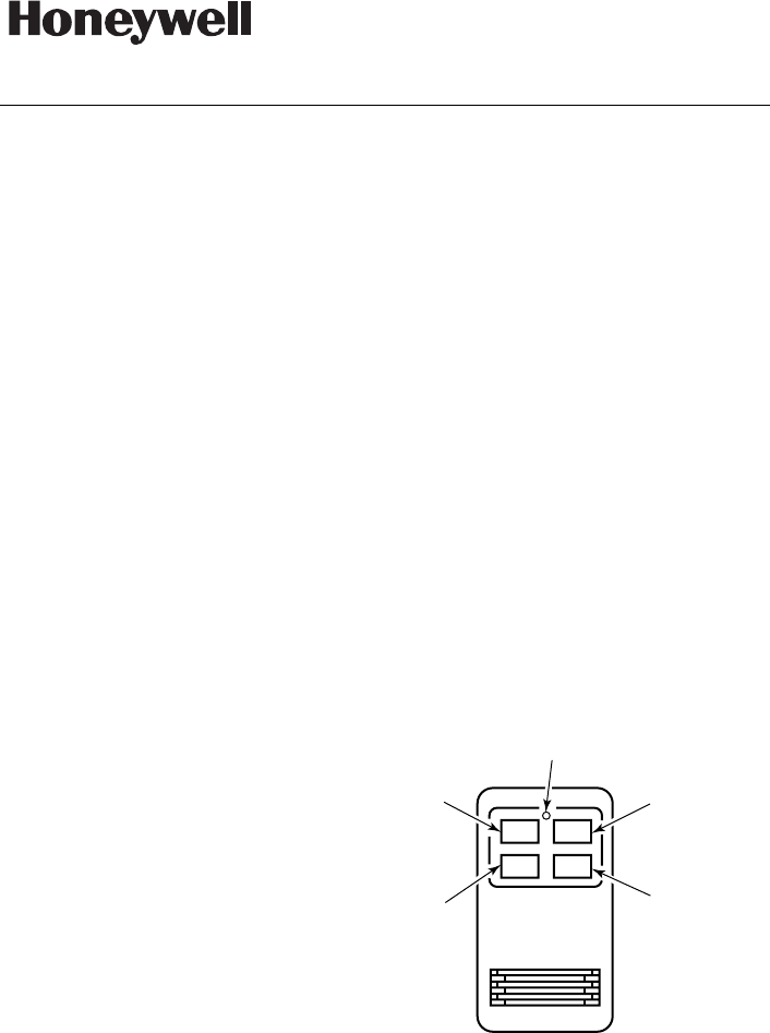
SELECTION OF FUNCTIONS FOR BUTTONS
For convenience, the 5801 is supplied with the buttons labeled with the functions shown
in Figure 1. Labels for these particular functions were chosen since they are
those likely to be selected for most
installations. However, additional
labels are provided for those cases
where other functions are desired;
simply attach the new label over the
existing one. In all cases, each
button must be programmed for its
desired function, as indicated in the
control unit’s installation instructions.
IMPORTANT NOTE:
If the “Function 4” button is not
used, it MUST be programmed as
a “Not used” zone type.
LED
FUNCTION
4
STAY
PANIC
OFF
AWAY
FUNCTION
2
FUNCTION
1
FUNCTION
3
5801-002-V0
Figure 1. 5801 Transmitter
PLEASE SEE FCC / IC
STATEMENTS AT
BOTTOM OF PAGE 2
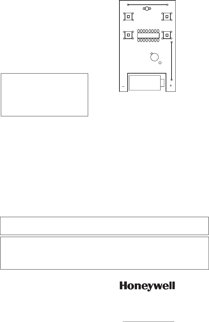
BATTERY INSTALLATION
1. Remove the cover by inserting the
blade of a small screw-driver into
the slot at the bottom of the case
and twisting.
2. Install the Lithium battery supplied
in the battery compart-ment,
observing correct polarity (see
Figure 2). Make sure the battery is
firmly seated.
3. Replace the cover (snap fit).
BATTERY CAUTION;
Risk of fire, explosion and burns. Do
not recharge, disassemble, heat
above 100"C, or incinerate. Dispose
of used batteries promptly. Keep away
from children.
5801-003-V0
LITHIUM
BATTERY
(ADEMCO 466)
Figure 2. 5801 (Cover Removed)
WALL-MOUNTING (OPTIONAL)
To wall-mount the unit, proceed as follows:
1. Disengage the supplied wall mounting plate from the unit by sliding it along the
case back.
2. Attach the mounting bracket in the desired location with the hooks pointing
upward, using the two screws supplied. The word TOP is molded along the upper
edge of the plate.
3. Locate the keyhole slots on the back of the transmitter case onto the bracket’s
hooks, and secure by sliding the case downward, firmly.
SPECIFICATIONS
Size: 4” x 2-1/4” x 13/16”`
102mm x 57mm x 21mm
LED: Flashes when unit transmits.
Battery: 3-volt Lithium. Use only ADEMCO 466, Duracell DL123A,
Panasonic CR123A, Sanyo CR123A.
REFER TO THE INSTALLATION INSTRUCTIONS FOR THE RECEIVER/CONTROL WITH WHICH
THIS DEVICE IS USED FOR WARRANTY INFORMATION AND FOR DETAILS REGARDING THE
LIMITATIONS OF THE ENTIRE ALARM SYSTEM.
This device complies with Part 15 of the FCC Rules. Operation is subject to the following two
conditions: (1) This device may not cause harmful interference (2) This device must accept any
interference received, including interference that may cause undesired operation. The user shall
not make any changes or modifications to the equipment unless authorized by the Installation
Instructions or User's Manual. Unauthorized changes or modifications could void the user's
authority to operate the equipment.
ÊN6478V3ÇŠ
N6478V3 5/05 Rev. B
2 Corporate Center Drive, Suite 100
P.O. Box 9040, Melville, NY 11747
Copyright © 2009 Honeywell International Inc.
www.honeywell.com/security