Ademco 8DL5804E-1 Wireless Key Transmitter User Manual N7674 6V3
Honeywell International Inc. Wireless Key Transmitter N7674 6V3
Ademco >
User Manual
N7674-6V3 9/08 Rev. A
ADEMCO 5804E
ADEMCO 5804EADEMCO 5804E
ADEMCO 5804E
WIRELESS KEY TRANSMITTER
WIRELESS KEY TRANSMITTERWIRELESS KEY TRANSMITTER
WIRELESS KEY TRANSMITTER
INSTALLATION AND SETUP GUIDE
GENERAL INFORMATION
The ADEMCO 5804E is a compact, 4-button
portable wireless transmitter intended for use only
with wireless alarm systems that support 5800
Series receivers. Each button on the transmitter
may be programmed for any zone response, but is
typically used for arming and disarming.
This device supports the High-Security mode,
which sends rolling-code encrypted messaging to
the RF receiver.
Important Note: This device must be used with
a 5881EN or a 6128RF (UL version) receiver.
The 5804E is powered by two replaceable lithium
batteries designed to provide up to 4 years of life.
For battery installation, see Replacing the
Batteries.
PROGRAMMING
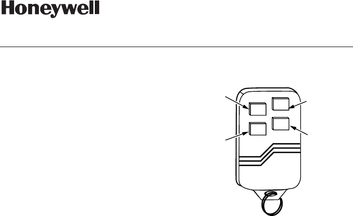
Each 5804E is assigned a unique serial number
during manufacture. Each button on the unit also
has a distinct "loop" number (refer to Figure 1) that
you must program into the control panel during
installation. Assign each button to an individual
zone and designate the Input Type as "BR"
(Button Type RF).
When you are prompted for the serial number,
either press and release twice the button you are
programming, or enter it manually through the
keypad.
For complete details on how to program the 5804E
transmitter's serial number at the control panel,
see the control unit's installation instructions.
Note: Buttons on this transmitter must be pressed
for at least 1/2 second to activate the transmitter.
This feature minimizes the possibility of accidental
transmissions.
ACTIVATING HIGH-SECURITY MODE
If Programming 5804E in the Control
1. Program the button in the control.
2. After programming is complete, exit
programming mode and wait 60 seconds.
3. Put the system in Go/No Go mode.
4. Press all 4 buttons on the 5804E at the same
time until the panel beeps.
5. To sync the device in High Security Mode,
press any button ONCE, until the panel beeps
indicating receipt.
NOTE: If no beep is heard, exit Go/No Go
mode, and repeat this procedure from Step 3.
6. Exit Go/No Go mode (user code + 1 (OFF)).
LOOP 4 LOOP 1
LOOP 2
ON
OFF
5804E-001-V0
LOOP 3
Figure 1: 5804E showing button designations
PROGRAMMING THE 5804E LOCALLY IN
AN RF KEYPAD (E.G., 6150RF)
Hold all 4 buttons down while enrolling the serial
number in the RF keypad.
USING TWO RECEIVERS IN HIGH-
SECURITY MODE
Enroll the 5804E into the receivers one at a time,
by disconnecting Receiver #2, enrolling as
described in “Activating High Security Mode”
(above). Then, disconnect Receiver #1, reconnect
Receiver #2, and repeat the enrollment procedure.
This process ensures proper High Security
operation with both receivers.
APPLYING COLORED ADHESIVE LABELS
AND BUTTONS
The 5804E is supplied with colored buttons (red
and blue) and colored adhesive identification
labels (blue, red, gray, and green). Each label has
a specified command function and symbol printed
on it, as well as an adhesive back for easy pasting.
To paste a label on a button, slowly peel off a
label with a selected function and paste it on the
button of the transmitter. If you decide later to re-
enroll a button, the label can be easily removed or
a new label pasted over the existing one.
Additional colored buttons (red and blue) are also
provided which can be used with or without the
labels. The buttons can be inserted only in the
areas provided for them (see Figure 3).
PLEASE GO TO THE BOTTOM
OF PAGE 2 FOR THE FCC & IC
STATEMENTS
To insert the colored buttons, do the
following:
1. Holding the transmitter with the buttons
face down, remove the case back by using
the blade of a small screwdriver to pry it
open (see Figure 2).
2. Carefully remove the PC board by its
rubber casing, making sure the board does
not come out of the casing. Do not bend
the exposed battery tabs on the PC board.
3. Replace the desired buttons, either red or
blue, in each button's designated opening
(see Figure 3).
4. When finished, replace the PC board,
making sure the button tabs on the board
face the four buttons, and snap the case
front and back together.
After inserting the new buttons, we recommend
you check the 5804E for proper operation.
5804E-002-V0
Figure 2: Battery tabs shown
Blue
Red
5804E-003-V0
Figure 3: 5804E shown open, buttons
facing down
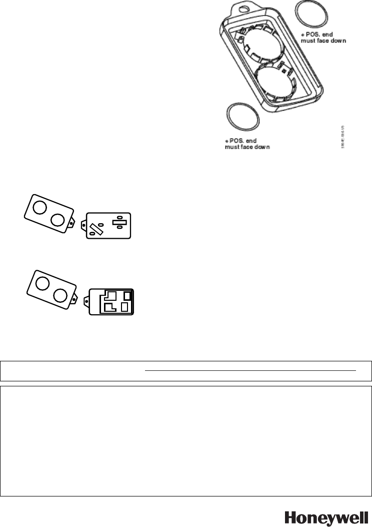
REPLACING THE BATTERIES
1. Remove case back by using the blade of a
small screwdriver to pry it open.
2. Remove old batteries.
3. Place batteries in case back locations (see
diagram above). + POS END MUST FACE
DOWN.
4. To close, snap case front and back
together.
Important Note: Do not remove
Printed
Circuit Board.
SPECIFICATIONS
Unit Dimensions:
2.25” W x 1.50”H x 0.5” D
57mm W x 38mm H x 12.7mm D
Battery:
Maxell CR2025, Duracell DL 2025, or Varta
CR2025
For the latest warranty information, go to: http://www.security.honeywell.com/hsc/resources/wa/index.html
And refer to the installation instructions for the receiver/control with which this device is used.
FEDERAL COMMUNICATIONS COMMISSION STATEMENTS:
The user shall not make any changes or modifications to the equipment unless authorized by the installation
Instructions or User's Manual. Unauthorized changes or modifications could void the user's authority to
operate the equipment.
FCC NOTICE
This device complies with Part 15 of FCC Rules, and RSS 210 of IC. Operation is subject to the following
two conditions: (1) This device may not cause harmful interference, and (2) This device must accept any
interference received, including interference that may cause undesired operation.
Cet appareil est conforme à la partie 15 des règles de la FCC & de RSS 210 des industries Canada. Son
fonctionnement est soumis aux conditions suivantes: (1) Cet appareil ne doit pas causer d'interferences
nuisibles. (2) Cet appareil doit accepter toute interference reçue y compris les interferences causant une
reception indesirable.
.ÊN7674-6V3UŠ
Honeywell International Inc.
2 Corporate Center Drive,
Suite 100, P.O. Box 9040,
Melville, NY 11747
Copyright 2008
N7674-6V3 9/08 Rev. A