Ademco 8DL5805 Key fob alarm accessory User Manual II with FCC Statements
Honeywell International Inc. Key fob alarm accessory II with FCC Statements
Ademco >
II with FCC Statements

5805-4/6
WIRELESS KEY TRANSMITTER
INSTALLATION INSTRUCTIONS
GENERAL INFORMATION
The 5805-4/6 is a compact, 4-button or 6-button
portable wireless transmitter intended for use
only with wireless alarm systems that support
5800 Series receivers. Each button on the
transmitter may be programmed for any zone
response, but is typically used for arming and
disarming.
This device supports the High-Security mode,
which sends rolling-code encrypted messaging
to the RF receiver.
Important Note: This device must be used
with a 5881EN or a 6128RF(UL version)
receiver.
The 5805-4/6 is powered by one replaceable
lithium battery designed to provide up to 4
years of life. For battery installation, see
Replacing the Batteries.
PROGRAMMING
Each 5805-4/6 is assigned a unique serial
number during manufacturing. Each button on
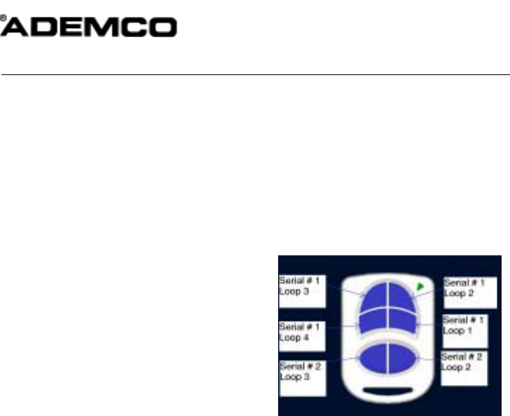
the unit also has a distinct "loop" number (refer
to Figure 1) that you must program into the
control panel during installation. Assign each
button to an individual zone and designate the
Input Type as "BR" (Button Type RF).
When you are prompted for the serial number,
both press and release twice the button you are
programming, or enter it manually through the
keypad.
For complete details on how to program the
5805-4/6 transmitter's serial number at the
control panel, see the control unit's installation
instructions.
Note: Buttons on this transmitter must be
pressed for at least 1/2 second to activate the
transmitter. This feature minimizes the
possibility of accidental transmissions.
ACTIVATING HIGH-SECURITY MODE
If Programming 5805-4/6 in the Control
1. Program the button in the control.
2. After programming is complete, exit
programming mode and wait 60 seconds.
3. Put the system in Go/No Go mode.
4. To enroll hold Loop1, Loop2, Loop3 and
loop 4 down at the same time until the
panel beeps.
5. To sync the device in High Security Mode,
press any button ONCE, until the panel
beeps indicating receipt.
6. For Second serial number Hold Loop1,
Loop4 of first Serial # and Loop 2, loop3 of
Second serial # at the same time until the
panel beeps.
NOTE: If no beep is heard, exit Go/No Go
mode, and repeat this procedure from Step 3.
7. Exit Go/No Go mode (user code + 1 (OFF)).
Figure 1: 5805-6 showing button designations
Note 1: To get second serial Loop 1 you need to
press and hold Serial # 2 Loop3 and Loop
2,To get Second serial loop 4 you need to
hold Serial # 1 Loop 3 and Serial # 2 loop 2
If Programming the 5805-4/6 Locally in the
6128RF
Hold Loop 1, Loop 2, Loop 3 and loop 4 Down
To enroll the First serial number in the
6128RF.
Hold Loop 1, Loop 4 of first Serial # and Loop 2,
loop 3 of Second serial # to enroll Second serial
number in the 6128RF
IF USING TWO RECEIVERS IN HIGH-
SECURITY MODE
Enroll the 5805-4/6 into the receivers one at a
time, by disconnecting Receiver #2, enrolling as
described in “Activating High Security Mode”
(above). Then, disconnect Receiver #1,
reconnect Receiver #2, and repeat the
enrollment procedure. This process ensures
proper High Security operation with both
receivers.

2
REPLACING THE BATTERY
1. Remove case back by using the blade of
a small screwdriver to pry it open.
2. Remove old battery
3. Place batter in case back locations (see
diagram above). - NEGATIVE END
MUST FACE DOWN.
4. To close, snap case front and back
together.
Important Note: Do not remove Printed
Circuit Board.
SPECIFICATIONS
Unit Dimensions:
55mm x 37mm x 12.7mm
Battery:
Maxell CR2032, Duracell DL 2032, or Varta
CR2032
FOR WARRANTY INFORMATION AND FOR DETAILS REGARDING THE LIMITATIONS OF THE
ENTIRE ALARM SYSTEM, REFER TO THE INSTALLATION INSTRUCTIONS FOR THE
RECEIVER/CONTROL WITH WHICH THIS DEVICE IS USED.
FCC ID: CFS8DL5805
165 Eileen Way, Syosset, New York 11791
Copyright © 1999 PITTWAY CORPORATION
THIS DEVICE COMPLIES WITH PART 15 OF FCC RULES. OPERATION IS SUBJECT TO THE FOLLOWING
TWO CONDITIONS: (1) THIS DEVICE MAY NOT CAUSE HARMFUL INTERFERENCE, AND (2) THIS DEVICE
MUST ACCEPT ANY INTERFERENCE RECEIVED, INCLUDING INTERFERENCE THAT MAY CAUSE
UNDESIRED OPERATION.