Ademco 8DL5808AP Photoelectronic Smoke/Heat Detector User Manual I56 918 14R indd

Honeywell International Inc. Photoelectronic Smoke/Heat Detector I56 918 14R indd

Contents

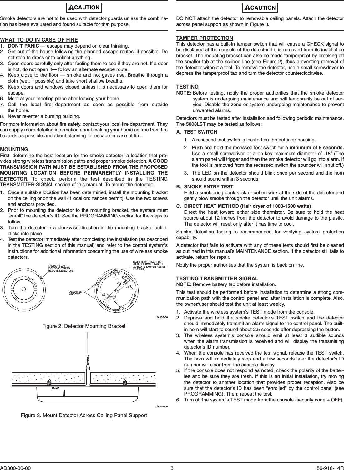
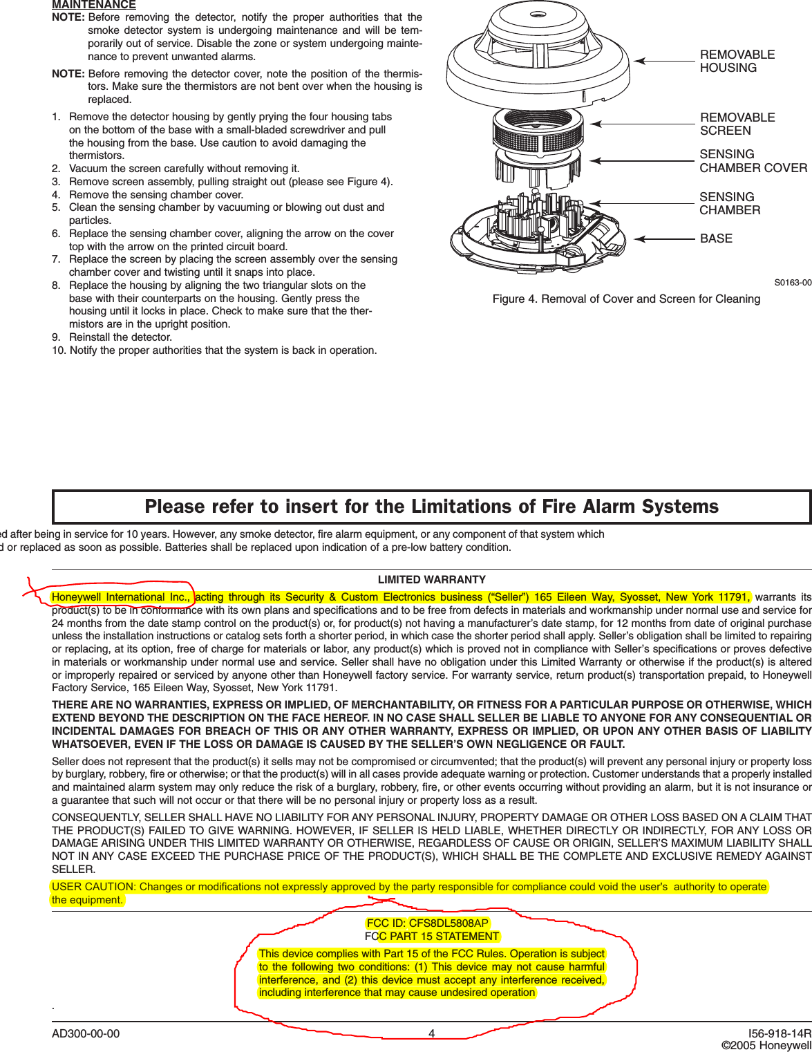
Users Manual Part 2 Revised

CAUTIONDO NOT attach the detector to removable ceiling panels. Attach the detector across panel support as shown in Figure 3.TAMPER PROTECTIONThis detector has a built-in tamper switch that will cause a CHECK signal to be displayed at the console of the detector if it is removed from its installation bracket. The mounting bracket can also be made tamperproof by breaking off the smaller tab at the scribed line (see Figure 2), thus preventing removal of the detector without a tool. To remove the detector, use a small screwdriver to depress the tamperproof tab and turn the detector counterclockwise.TESTINGNOTE:  Before  testing,  notify  the  proper  authorities  that  the  smoke  detector system is undergoing maintenance and will temporarily be out of ser-vice. Disable the zone or system undergoing maintenance to prevent unwanted alarms.Detectors must be tested after installation and following periodic maintenance. The 5808LST may be tested as follows:A.  TEST SWITCH  1.  A recessed test switch is located on the detector housing.  2.  Push and hold the recessed test switch for a minimum of 5 seconds. Use a  small screwdriver or  allen key maximum diameter of  .18” (The alarm panel will trigger and then the smoke detector will go into alarm. If the tool is removed from the recessed switch the sounder will shut off.)  3.  The LED  on the detector should blink once per second and  the horn should sound within 3 seconds.B.  SMOKE ENTRY TEST  Hold a smoldering punk stick or cotton wick at the side of the detector and gently blow smoke through the detector until the unit alarms.C.  DIRECT HEAT METHOD (Hair dryer of 1000-1500 watts)  Direct  the  heat  toward  either  side  thermistor.  Be  sure  to  hold  the  heat source about 12 inches from the detector to avoid damage to the plastic. The detector will reset only after it has time to cool.Smoke  detection  testing  is  recommended  for  verifying  system  protection capability.A detector that fails to activate with any of these tests should first be cleaned as outlined in this manual’s MAINTENANCE section. If the detector still fails to activate, return for repair.Notify the proper authorities that the system is back on line.TESTING TRANSMITTER SIGNALNOTE: Remove battery tab before installation. This test should be performed before installation to determine a strong com-munication path with the control panel and after installation is complete. Also, the owner/user should test the unit at least weekly.1.  Activate the wireless system’s TEST mode from the console.2.  Depress  and  hold  the  smoke  detector’s  TEST  switch  and  the  detector should immediately transmit an alarm signal to the control panel. The built-in horn will start to sound about 2.5 seconds after depressing the button.3.  The  wireless  system’s  console  should  emit  at  least  3  audible  sounds when the alarm transmission is received and  will display the transmitting detector’s ID number.4.  When the console has received the test signal, release the TEST switch. The horn will immediately stop and a  few seconds later the detector’s ID number will clear from the console display.5.  If the console does not respond as noted, check the polarity of the batter-ies and be  sure  they  are  fresh. If  this  is  an  initial installation, try  moving the  detector  to  another  location  that  provides  proper  reception.  Also  be sure that  the detector’s ID  has been “enrolled” by  the  control panel (see PROGRAMMING). Then, repeat the test.6.  Turn off the system’s TEST mode from the console (security code + OFF).CAUTIONSmoke detectors are not to be used with detector guards unless the combina-tion has been evaluated and found suitable for that purpose.WHAT TO DO IN CASE OF FIRE1.  DON’T PANIC — escape may depend on clear thinking.2.  Get out of the house following the planned escape routes, if possible. Do not stop to dress or to collect anything.3.  Open doors carefully only after feeling them to see if they are hot. If a door is hot, do not open it— follow an alternate escape route.4.  Keep close to the floor  —  smoke and  hot gases rise. Breathe through a cloth (wet, if possible) and take short shallow breaths.5.  Keep doors and  windows closed unless it  is necessary to  open them  for escape. 6.  Meet at your meeting place after leaving your home.7.  Call  the  local  fire  department  as  soon  as  possible  from  outside  the home.8.   Never re-enter a burning building.For more information about fire safety, contact your local fire department. They can supply more detailed information about making your home as free from fire hazards as possible and about planning for escape in case of fire.MOUNTINGFirst, determine the best location for the smoke detector; a location that pro-vides strong wireless transmission paths and proper smoke detection. A GOOD TRANSMISSION PATH MUST BE ESTABLISHED FROM THE PROPOSED MOUNTING  LOCATION  BEFORE  PERMANENTLY  INSTALLING  THE DETECTOR.  To  check,  perform  the  test  described  in  the  TESTING TRANSMITTER SIGNAL section of this manual. To mount the detector:1.  Once a suitable location has been determined, install the mounting bracket on the ceiling or on the wall (if local ordinances permit). Use the two screws and anchors provided.2.  Prior to  mounting the detector to the  mounting bracket, the  system must “enroll” the detector’s ID. See the PROGRAMMING section for the steps to follow.3.  Turn the  detector in  a clockwise direction in the  mounting bracket until it clicks into place.4.  Test the detector immediately after completing the installation (as described in the TESTING section of this manual) and refer to  the control system’s instructions for additional information concerning the use of wireless smoke detectors.   TAMPER SLOT(DEPRESS TAB TOREMOVE DETECTOR)TAMPER RESISTANT TAB (CUT OFF SMALL TAB TO ACTIVATE TAMPER-RESIST FEATURE)ALIGNMENTARROWSS0158-00Figure 2. Detector Mounting BracketS0162-00Figure 3. Mount Detector Across Ceiling Panel SupportAD300-00-00  3  I56-918-14R
AD300-00-00  4  I56-918-14R©2005 HoneywellLIMITED WARRANTYHoneywell  International  Inc.,  acting  through  its  Security  &  Custom  Electronics  business  (“Seller”)  165  Eileen  Way,  Syosset,  New  York  11791,  warrants  its product(s) to be in conformance with its own plans and specifications and to be free from defects in materials and workmanship under normal use and service for 24 months from the date stamp control on the product(s) or, for product(s) not having a manufacturer’s date stamp, for 12 months from date of original purchase unless the installation instructions or catalog sets forth a shorter period, in which case the shorter period shall apply. Seller’s obligation shall be limited to repairing or replacing, at its option, free of charge for materials or labor, any product(s) which is proved not in compliance with Seller’s specifications or proves defective in materials or workmanship under normal use and service. Seller shall have no obligation under this Limited Warranty or otherwise if the product(s) is altered or improperly repaired or serviced by anyone other than Honeywell factory service. For warranty service, return product(s) transportation prepaid, to Honeywell Factory Service, 165 Eileen Way, Syosset, New York 11791. THERE ARE NO WARRANTIES, EXPRESS OR IMPLIED, OF MERCHANTABILITY, OR FITNESS FOR A PARTICULAR PURPOSE OR OTHERWISE, WHICH EXTEND BEYOND THE DESCRIPTION ON THE FACE HEREOF. IN NO CASE SHALL SELLER BE LIABLE TO ANYONE FOR ANY CONSEQUENTIAL OR INCIDENTAL DAMAGES FOR BREACH OF THIS OR ANY OTHER WARRANTY, EXPRESS OR IMPLIED, OR UPON ANY OTHER BASIS OF LIABILITY WHATSOEVER, EVEN IF THE LOSS OR DAMAGE IS CAUSED BY THE SELLER’S OWN NEGLIGENCE OR FAULT.Seller does not represent that the product(s) it sells may not be compromised or circumvented; that the product(s) will prevent any personal injury or property loss by burglary, robbery, fire or otherwise; or that the product(s) will in all cases provide adequate warning or protection. Customer understands that a properly installed and maintained alarm system may only reduce the risk of a burglary, robbery, fire, or other events occurring without providing an alarm, but it is not insurance or a guarantee that such will not occur or that there will be no personal injury or property loss as a result.CONSEQUENTLY, SELLER SHALL HAVE NO LIABILITY FOR ANY PERSONAL INJURY, PROPERTY DAMAGE OR OTHER LOSS BASED ON A CLAIM THAT THE PRODUCT(S) FAILED TO GIVE WARNING. HOWEVER, IF SELLER IS HELD LIABLE, WHETHER DIRECTLY OR INDIRECTLY, FOR ANY LOSS OR DAMAGE ARISING UNDER THIS LIMITED WARRANTY OR OTHERWISE, REGARDLESS OF CAUSE OR ORIGIN, SELLER’S MAXIMUM LIABILITY SHALL NOT IN ANY CASE EXCEED THE PURCHASE PRICE OF THE PRODUCT(S), WHICH SHALL BE THE COMPLETE AND EXCLUSIVE REMEDY AGAINST SELLER.USER CAUTION: Changes or modifications not expressly approved by the party responsible for compliance could void the user's  authority to operate  the equipment.FCC ID: CFS8DL5808APFCC PART 15 STATEMENTThis device complies with Part 15 of the FCC Rules. Operation is subject to  the  following two  conditions:  (1) This  device may  not  cause  harmful interference, and (2) this device must accept any interference received, including interference that may cause undesired operation.Smoke detectors shall be replaced after being in service for 10 years. However, any smoke detector, fire alarm equipment, or any component of that system which fails prior to that shall be repaired or replaced as soon as possible. Batteries shall be replaced upon indication of a pre-low battery condition.MAINTENANCENOTE:  Before  removing  the  detector,  notify  the  proper  authorities  that  the smoke  detector  system  is  undergoing  maintenance  and  will  be  tem-porarily out of service. Disable the zone or system undergoing mainte-nance to prevent unwanted alarms.NOTE:  Before removing the detector cover,  note the position of the thermis-tors. Make sure the thermistors are not bent over when the housing is replaced.1.   Remove the detector housing by gently prying the four housing tabs    on the bottom of the base with a small-bladed screwdriver and pull    the housing from the base. Use caution to avoid damaging the    thermistors. 2.  Vacuum the screen carefully without removing it.3.   Remove screen assembly, pulling straight out (please see Figure 4).4.  Remove the sensing chamber cover.5.   Clean the sensing chamber by vacuuming or blowing out dust and    particles.6.  Replace the sensing chamber cover, aligning the arrow on the cover    top with the arrow on the printed circuit board.7.   Replace the screen by placing the screen assembly over the sensing    chamber cover and twisting until it snaps into place.8.   Replace the housing by aligning the two triangular slots on the    base with their counterparts on the housing. Gently press the    housing until it locks in place. Check to make sure that the ther-   mistors are in the upright position.9.   Reinstall the detector.10. Notify the proper authorities that the system is back in operation.REMOVABLEHOUSINGBASEREMOVABLESCREENSENSINGCHAMBER COVERSENSINGCHAMBERS0163-00Figure 4. Removal of Cover and Screen for Cleaning Please refer to insert for the Limitations of Fire Alarm Systems

Navigation menu