Ademco 8DL5808LP-1 smoke detector transmitter User Manual I56 918 14R indd
Honeywell International Inc. smoke detector transmitter I56 918 14R indd
Ademco >
II users manual with FCC Part 15 statment
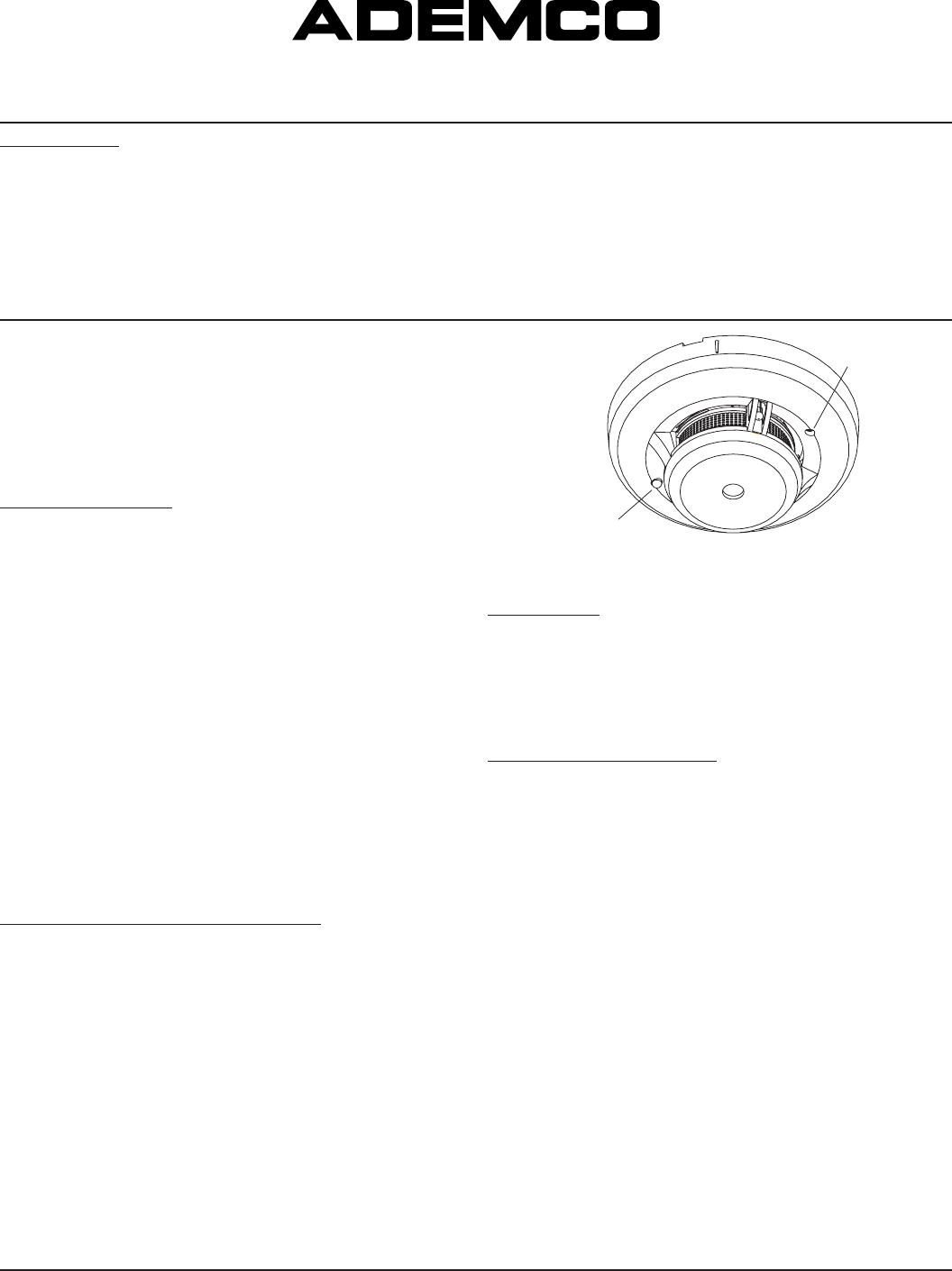
Indicator Light
Pulsing: Normal/Thermal Alarm
Fast Blink: Smoke Alarm
None: Call for Service
Test Switch
S0162-00
Figure 1. 5808LST Wireless Smoke/Heat Detector
PROGRAMMING
The smoke detector’s ID must be enrolled in the control panel during installa-
tion of the system. The 5808LST must be enrolled on loop 1 as an input “Type
3” (supervised RF).
With the control panel in the programming mode, enter the 7 digit serial number
that is on the label of the 5808LST. For confirmation, press the test switch to
send a transmission to the control panel.
See the control unit’s installation instructions for further details.
SMOKE DETECTOR LIMITATIONS
• Smoke detectors will not sense a fire if the smoke does not reach the
sensor or if the air temperature does not reach 135° F. In order for a
smoke detector to sense smoke, it must be installed in the immediate vicin-
ity of the fire. In addition, smoke from fires in chimneys, in walls, on roofs,
in remote parts of the building, or on another level from where the smoke
detector is located, may not reach the smoke detector quickly enough for
occupants to escape unharmed. For this reason, installer shall install
smoke detectors on every level, in every sleeping area, and in every
bedroom of the household.
• Smoke detectors may not be heard. The alarm horn in this smoke detector
meets or exceeds current Underwriter’s Laboratories standards. However, if
the smoke detector is not located in the same room as the occupant, or if
it is blocked by a closed door or normal noise, the alarm horn may not be
heard. In addition, sound sleepers, or persons who are under the influence of
drugs or alcohol may not hear the alarm or be able to react to it. Therefore,
locate this smoke detector, which has a sounder rated at 85 dB at 10
feet, on every level, in every sleeping area, and in every bedroom of the
household.
• In general, detectors may not always warn you about fires caused by care-
lessness and safety hazards like smoking in bed, violent explosions, escaping
gas, improper storage of flammable materials, overloaded electrical circuits,
children playing with matches, or arson.
• Smoke detectors are not fool-proof. Like all electronic devices, smoke
detectors have limitations. No type of smoke detector can sense every
kind of fire every time. In addition, smoke from slow, smoldering fires
rises slowly and may not reach the smoke detector until actual flame
breaks out. This type of smoke may not reach the smoke detector in
time for occupants to escape unharmed.
• Smoke detectors are not a substitute for life or property insurance.
Though smoke detectors have been responsible for saving many lives, they
are not warranted or implied to protect lives or property in the event of a fire.
Before installing detectors, please thoroughly read these installation instruc-
tions and Manual I56-407, Guide for Proper Use of System Smoke Detectors,
which provides detailed information on detector spacing, placement, zoning,
wiring, and special applications. Copies of this manual are available from
ADEMCO.
NOTICE: This manual should be left with the owner/user of this equipment.
IMPORTANT: This detector must be tested and maintained regularly following
NFPA 72 requirements. The detector should be cleaned at least once a year.
GENERAL DESCRIPTION
The 5808LST photoelectronic smoke/heat detector with built-in wireless trans-
mitter is intended for use with wireless alarm systems that support 5800 series
devices. Refer to control/communicator installation instructions for compatibil-
ity. The 5808LST smoke/heat detector can be used with 5881 series (L, M, H)
and 5881EH receivers for residential installations. For commercial installations,
the 5881EH receiver should be used. The transmitter can send alarm, tamper,
maintenance (when control panels are equipped to process maintenance
signals), and battery condition messages to the system’s receiver. The main-
tenance signal fully complies with the sensitivity test requirement specified in
NFPA 72, 7-2.2. Refer to the wireless system’s instructions for the maximum
number of transmitters that can be supported.
The 5808LST will sound its built-in temporal horn when smoke activates the
detector (also the LED also flashes rapidly), or when the air temperature
reaches 135° F (the LED flashes normally, about once every 40 seconds). A
message is also sent to the wireless control panel and the smoke detector’s ID
number is displayed at the console. The alarm message is transmitted every 4
seconds until the smoke condition has cleared and the detector has reset. After
the horn stops, a RESTORE message is transmitted to the control panel and the
ID number can be cleared from the panel. During normal and low battery condi-
tions, the LED flashes approximately once every 40 seconds. The built-in Drift
Compensation algorithm automatically maintains the sensitivity of the detector.
Once the detector reaches its limit of compensation, it transmits a maintenance
signal to the panel. In maintenance condition, the LED stops flashing.
BATTERY INSTALLATION AND REPLACEMENT
The 5808LST is powered by two 3-volt CR123A or DL123A Lithium batteries
(included). The detector checks for low batteries at least every 60 minutes. If
a low battery is detected, the transmitter sends a low battery message to the
control panel, which beeps and displays the detector’s ID. This condition will
exist for a minimum of seven days, and then the detector’s horn will “chirp”
about every 40 seconds. The batteries should be replaced BEFORE the chirps
begin. Be sure to replace BOTH batteries with fresh ones.
To replace batteries:
1. Remove the detector from its mounting plate by twisting the detector coun-
terclockwise. Remove batteries, and dispose properly.
2. Install two new 3-volt CR123A Lithium batteries in the battery compartment.
Follow the polarity diagram inside the compartment.
3. Reinstall the smoke detector onto the mounting plate by turning the detec-
tor clockwise.
4. Test the detector as described in the TESTING TRANSMITTER SIGNAL
section of this manual. The LED should flash about once every 40 seconds
to indicate normal operation. If the batteries are not installed correctly, the
smoke detector will not operate and the batteries may be damaged. If the
detector does not appear to be sending a signal during any of the tests,
check for correct battery installation.
AD300-00-00 1 I56-918-14R
Honeywell, 165 Eileen Way, Syosset, New York 11791
5808LST Photoelectronic Smoke/Heat Detector with
Built-in Wireless Transmitter Installation Instructions
SPECIFICATIONS
Power Source: Two 3-volt CR123A Lithium Batteries (included). (Replace with Duracell DL123A, Sanyo CR123A, Panasonic CR123A
or ADEMCO 466.)
Height: 2.05 inches (52 mm)
Diameter: 5.0 inches (127 mm) without adapter bracket
5.5 inches (140 mm) with adapter bracket
Weight: 8.5 oz. (241 g) without batteries
Operating Ambient Temperature Range: 0° to 38° C (32° to 100° F)
Operating Humidity Range: 5% to 95% Relative Humidity
Heat Sensor: 135° F Fixed Temperature Electronic Thermistors
Agency Listings: UL 268 – Commercial and Residential Installations
®
• Install detectors on the ceiling as close to the center of the room as possible.
If this is not practical, install it on the ceiling no closer than 4 inches (10 cm)
from any wall or corner. (See Figure 4.)
• If wall-mounting is permitted by local and state codes, and ceiling mounting
is not practical, install detectors on an inside wall between 4 and 6 inches (10
and 15 cm) from the ceiling. (See Figure 4.)
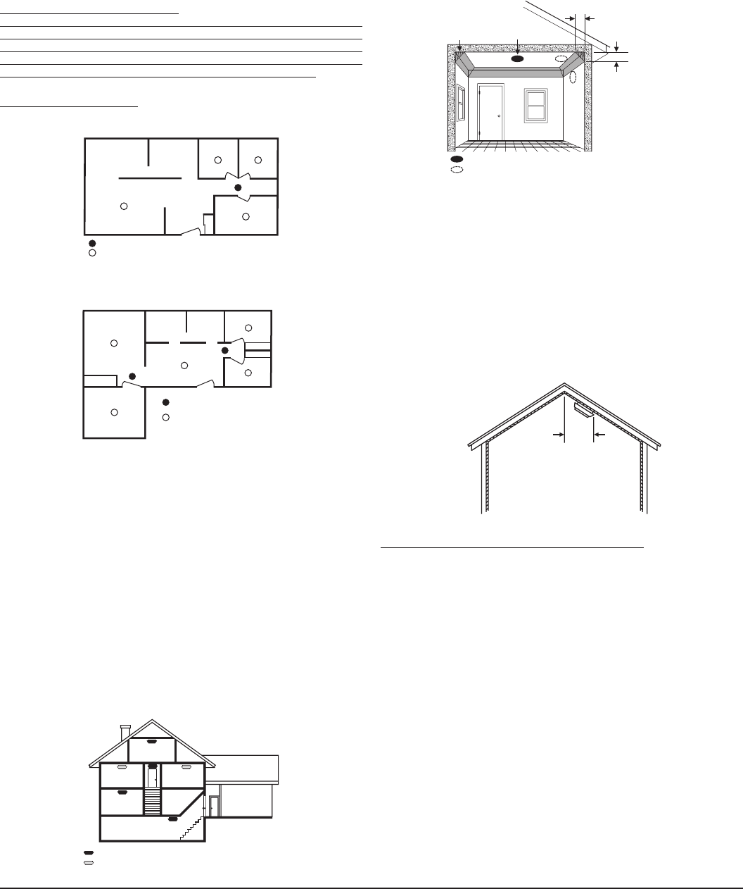
Figure 4: Recommended smoke detector mounting locations:
BEST LOCATION
ACCEPTABLE LOCATION
DEAD AIR
SPACE
BEST IN CENTER
OF CEILING
NO CLOSER THAN 4" (10 cm)
FROM SIDE WALL
MOUNT ON WALL
AT LEAST 4" (10 cm)
FROM CEILING
NO MORE
THAN 6" (15 cm)
FROM CEILING
S0147-00
• Put detectors at both ends of a bedroom hallway if the hallway is more than
30 feet (9 meters) long. In addition, large rooms will require more than a single
detector if the room is over 900 square feet.
• Rooms or areas that do not have smooth ceilings, or which have short, tran-
som-type walls coming down from the ceiling require additional detectors.
• Install second-floor detectors on the ceiling at the top of the first-to-second
floor stairwell. Be sure no door or other obstruction blocks the path of smoke
to the detector.
• In rooms with sloped, peaked, or gabled ceilings, install detectors 3 feet (0.9
meter) measured down on the slant from the highest point of the ceiling. See
Figure 5.
Figure 5: Recommended smoke detector location in rooms with sloped, gabled
or peaked ceilings:
HORIZONTAL
DISTANCE
FROM PEAK
3 FEET
(.9M)
S0148-00
Where Smoke Detectors Should NOT Be Installed
• In or near areas where combustion particles are normally present such
as kitchens; in garages where there are particles of combustion in vehicle
exhausts; near furnaces, hot water heaters, or gas space heaters. Install
detectors at least 20 feet (6 meters) away from kitchens and other areas
where combustion particles are normally present.
• On the ceiling in rooms next to kitchens where there is no transom
between the kitchen and these rooms. Instead, install the smoke detector on
an inside wall, furthest from the kitchen. Be sure not to install smoke detectors
within 4” of the ceiling or any corner or more than 6” from the ceiling.
• In damp or very humid areas, or next to bathrooms with showers. The
moisture in humid air can enter the sensing chamber as water vapor, then
cool and condense into droplets that cause a nuisance alarm. Install detec-
tors at least 5 feet (1.5 meters) away from bathrooms.
• In very cold or very hot rooms or areas. Operating temperature of the
smoke detector is 40°F to 100°F (4°C to 38°C).
• In dusty, dirty, or insect-infested areas. Dust and dirt can build up on the
detector’s sensing chamber and make it overly sensitive, or can block open-
ings to the sensing chamber and keep the detector from sensing smoke.
• Near fresh air inlets or returns or excessively drafty areas. Air condition-
ers, heaters, fans, and fresh air intakes and returns can drive smoke away
from smoke detectors, making the detectors less effective.
• In dead air spaces at the top of a peaked ceiling or wall/ceiling intersect.
Dead air may prevent smoke from reaching a detector.
• Near fluorescent light fixtures. Install detectors at least 10 feet (3 meters)
away from such light fixtures.
• To keep your equipment in excellent working order, ongoing maintenance is
required per the manufacturer’s recommendations and UL and NFPA stan-
dards. At a minimum, the requirements of Chapter 7 of NFPA 72, the National
Fire Alarm Code, shall be followed. A preventative maintenance agreement
should be arranged through the local manufacturer’s representative. Though
smoke detectors are designed for long life, they may fail at any time. Any
smoke detector, fire alarm equipment, or any component of that system which
fails shall be repaired or replaced as soon as possible.
Where to Install Smoke Detectors
Warning: As a minimum requirement, smoke detectors must be installed in
accordance with the National Fire Protection Agency (NFPA) Standard 72,
Chapter 5, which defines the standards for the National Fire Alarm Code
(National Fire Protection Association, Batterymarch Park, MA 02269-9101). In
addition, observe all local and national building and electrical codes.
Proper Detector Location:
Figure 1: Recommended smoke detector protection for single-floor residence
with only one sleeping area
DINING ROOM KITCHEN BEDROOM BEDROOM
BEDROOMLIVING ROOM
SMOKE DETECTORS FOR MINIMUM PROTECTION
SMOKE DETECTORS FOR MORE PROTECTION AND
REQUIRED IN NEW CONSTRUCTION
S0144-00
Figure 2: Recommended smoke detector protection for single-floor residence
with more than one sleeping area:
BEDROOM
SMOKE DETECTORS FOR
MINIMUM PROTECTION
SMOKE DETECTORS FOR
MORE PROTECTION AND
REQUIRED IN NEW CONSTRUCTION
BEDROOM
BEDROOM
LIVING ROOM
DINING
ROOM
KITCHENFAMILY ROOM
S0145-00
NFPA 72, Chapter 2, Section 2-2.1.1.1 states as follows: “Smoke detectors
shall be installed outside of each separate sleeping area in the immediate
vicinity of the bedrooms and on each additional story of the family living unit,
including basements and excluding crawl spaces and unfinished attics. In new
construction, a smoke detector also shall be installed in each sleeping room.”
The above NFPA standard is a minimum requirement for smoke detector
installation. For better protection, we also require the installation of a
smoke detector inside every bedroom in existing construction.
• Install a minimum of two smoke detectors in any household, no matter
how small it is.
• Put a smoke detector in the hallway outside of every separate bedroom
area. (See Figure 1.) A minimum of two detectors are required in homes with
two bedroom areas. (See Figure 2.)
• Put a smoke detector on every level of a multi-level residence. (See
Figure 3.)
• Install basement detectors on the ceiling at the bottom of the basement stair-
well. (See Figure 3.)
Figure 3: Recommended smoke detector protection for a multi-level resi-
dence:
BEDROOM
BEDROOM BEDROOM
LIVING
ROOM
KITCHEN
BASEMENT
GARAGE
SMOKE DETECTORS FOR MINIMUM PROTECTION
SMOKE DETECTORS FOR MORE PROTECTION AND
REQUIRED IN NEW CONSTRUCTION
S0146-00
AD300-00-00 2 I56-918-14R
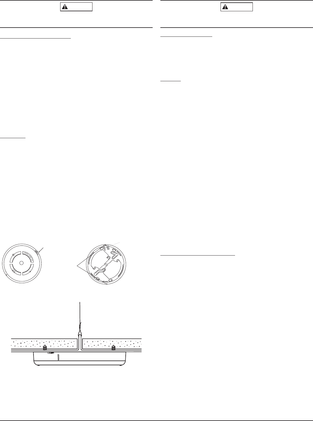
CAUTION
DO NOT attach the detector to removable ceiling panels. Attach the detector
across panel support as shown in Figure 3.
TAMPER PROTECTION
This detector has a built-in tamper switch that will cause a CHECK signal to
be displayed at the console of the detector if it is removed from its installation
bracket. The mounting bracket can also be made tamperproof by breaking off
the smaller tab at the scribed line (see Figure 2), thus preventing removal of
the detector without a tool. To remove the detector, use a small screwdriver to
depress the tamperproof tab and turn the detector counterclockwise.
TESTING
NOTE: Before testing, notify the proper authorities that the smoke detector
system is undergoing maintenance and will temporarily be out of ser-
vice. Disable the zone or system undergoing maintenance to prevent
unwanted alarms.
Detectors must be tested after installation and following periodic maintenance.
The 5808LST may be tested as follows:
A. TEST SWITCH
1. A recessed test switch is located on the detector housing.
2. Push and hold the recessed test switch for a minimum of 5 seconds.
Use a small screwdriver or allen key maximum diameter of .18” (The
alarm panel will trigger and then the smoke detector will go into alarm. If
the tool is removed from the recessed switch the sounder will shut off.)
3. The LED on the detector should blink once per second and the horn
should sound within 3 seconds.
B. SMOKE ENTRY TEST
Hold a smoldering punk stick or cotton wick at the side of the detector and
gently blow smoke through the detector until the unit alarms.
C. DIRECT HEAT METHOD (Hair dryer of 1000-1500 watts)
Direct the heat toward either side thermistor. Be sure to hold the heat
source about 12 inches from the detector to avoid damage to the plastic.
The detector will reset only after it has time to cool.
Smoke detection testing is recommended for verifying system protection
capability.
A detector that fails to activate with any of these tests should first be cleaned
as outlined in this manual’s MAINTENANCE section. If the detector still fails to
activate, return for repair.
Notify the proper authorities that the system is back on line.
TESTING TRANSMITTER SIGNAL
NOTE: Remove battery tab before installation.
This test should be performed before installation to determine a strong com-
munication path with the control panel and after installation is complete. Also,
the owner/user should test the unit at least weekly.
1. Activate the wireless system’s TEST mode from the console.
2. Depress and hold the smoke detector’s TEST switch and the detector
should immediately transmit an alarm signal to the control panel. The built-
in horn will start to sound about 2.5 seconds after depressing the button.
3. The wireless system’s console should emit at least 3 audible sounds
when the alarm transmission is received and will display the transmitting
detector’s ID number.
4. When the console has received the test signal, release the TEST switch.
The horn will immediately stop and a few seconds later the detector’s ID
number will clear from the console display.
5. If the console does not respond as noted, check the polarity of the batter-
ies and be sure they are fresh. If this is an initial installation, try moving
the detector to another location that provides proper reception. Also be
sure that the detector’s ID has been “enrolled” by the control panel (see
PROGRAMMING). Then, repeat the test.
6. Turn off the system’s TEST mode from the console (security code + OFF).
CAUTION
Smoke detectors are not to be used with detector guards unless the combina-
tion has been evaluated and found suitable for that purpose.
WHAT TO DO IN CASE OF FIRE
1. DON’T PANIC — escape may depend on clear thinking.
2. Get out of the house following the planned escape routes, if possible. Do
not stop to dress or to collect anything.
3. Open doors carefully only after feeling them to see if they are hot. If a door
is hot, do not open it— follow an alternate escape route.
4. Keep close to the floor — smoke and hot gases rise. Breathe through a
cloth (wet, if possible) and take short shallow breaths.
5. Keep doors and windows closed unless it is necessary to open them for
escape.
6. Meet at your meeting place after leaving your home.
7. Call the local fire department as soon as possible from outside
the home.
8. Never re-enter a burning building.
For more information about fire safety, contact your local fire department. They
can supply more detailed information about making your home as free from fire
hazards as possible and about planning for escape in case of fire.
MOUNTING
First, determine the best location for the smoke detector; a location that pro-
vides strong wireless transmission paths and proper smoke detection. A GOOD
TRANSMISSION PATH MUST BE ESTABLISHED FROM THE PROPOSED
MOUNTING LOCATION BEFORE PERMANENTLY INSTALLING THE
DETECTOR. To check, perform the test described in the TESTING
TRANSMITTER SIGNAL section of this manual. To mount the detector:
1. Once a suitable location has been determined, install the mounting bracket
on the ceiling or on the wall (if local ordinances permit). Use the two screws
and anchors provided.
2. Prior to mounting the detector to the mounting bracket, the system must
“enroll” the detector’s ID. See the PROGRAMMING section for the steps to
follow.
3. Turn the detector in a clockwise direction in the mounting bracket until it
clicks into place.
4. Test the detector immediately after completing the installation (as described
in the TESTING section of this manual) and refer to the control system’s
instructions for additional information concerning the use of wireless smoke
detectors.
TAMPER SLOT
(DEPRESS TAB TO
REMOVE DETECTOR)
TAMPER RESISTANT TAB
(CUT OFF SMALL TAB TO
ACTIVATE TAMPER-RESIST
FEATURE)
ALIGNMENT
ARROWS
S0158-00
Figure 2. Detector Mounting Bracket
S0162-00
Figure 3. Mount Detector Across Ceiling Panel Support
AD300-00-00 3 I56-918-14R
AD300-00-00 4 I56-918-14R
©2005 Honeywell
LIMITED WARRANTY
Honeywell International Inc., acting through its Security & Custom Electronics business (“Seller”) 165 Eileen Way, Syosset, New York 11791, warrants its
product(s) to be in conformance with its own plans and specifications and to be free from defects in materials and workmanship under normal use and service for
24 months from the date stamp control on the product(s) or, for product(s) not having a manufacturer’s date stamp, for 12 months from date of original purchase
unless the installation instructions or catalog sets forth a shorter period, in which case the shorter period shall apply. Seller’s obligation shall be limited to repairing
or replacing, at its option, free of charge for materials or labor, any product(s) which is proved not in compliance with Seller’s specifications or proves defective
in materials or workmanship under normal use and service. Seller shall have no obligation under this Limited Warranty or otherwise if the product(s) is altered
or improperly repaired or serviced by anyone other than Honeywell factory service. For warranty service, return product(s) transportation prepaid, to Honeywell
Factory Service, 165 Eileen Way, Syosset, New York 11791.
THERE ARE NO WARRANTIES, EXPRESS OR IMPLIED, OF MERCHANTABILITY, OR FITNESS FOR A PARTICULAR PURPOSE OR OTHERWISE, WHICH
EXTEND BEYOND THE DESCRIPTION ON THE FACE HEREOF. IN NO CASE SHALL SELLER BE LIABLE TO ANYONE FOR ANY CONSEQUENTIAL OR
INCIDENTAL DAMAGES FOR BREACH OF THIS OR ANY OTHER WARRANTY, EXPRESS OR IMPLIED, OR UPON ANY OTHER BASIS OF LIABILITY
WHATSOEVER, EVEN IF THE LOSS OR DAMAGE IS CAUSED BY THE SELLER’S OWN NEGLIGENCE OR FAULT.
Seller does not represent that the product(s) it sells may not be compromised or circumvented; that the product(s) will prevent any personal injury or property loss
by burglary, robbery, fire or otherwise; or that the product(s) will in all cases provide adequate warning or protection. Customer understands that a properly installed
and maintained alarm system may only reduce the risk of a burglary, robbery, fire, or other events occurring without providing an alarm, but it is not insurance or
a guarantee that such will not occur or that there will be no personal injury or property loss as a result.
CONSEQUENTLY, SELLER SHALL HAVE NO LIABILITY FOR ANY PERSONAL INJURY, PROPERTY DAMAGE OR OTHER LOSS BASED ON A CLAIM THAT
THE PRODUCT(S) FAILED TO GIVE WARNING. HOWEVER, IF SELLER IS HELD LIABLE, WHETHER DIRECTLY OR INDIRECTLY, FOR ANY LOSS OR
DAMAGE ARISING UNDER THIS LIMITED WARRANTY OR OTHERWISE, REGARDLESS OF CAUSE OR ORIGIN, SELLER’S MAXIMUM LIABILITY SHALL
NOT IN ANY CASE EXCEED THE PURCHASE PRICE OF THE PRODUCT(S), WHICH SHALL BE THE COMPLETE AND EXCLUSIVE REMEDY AGAINST
SELLER.
This warranty replaces any previous warranties and is the only warranty made by Seller on this product(s). No increase or alteration, written or verbal, of the
obligations of this Limited Warranty is authorized.
FCC ID: CFS8DL5808LP-1
FCC PART 15 STATEMENT
This device complies with Part 15 of the FCC Rules. Operation is subject
to the following two conditions: (1) This device may not cause harmful
interference, and (2) this device must accept any interference received,
including interference that may cause undesired operation.
CANADA: 573F-5808LP1
Smoke detectors shall be replaced after being in service for 10 years. However, any smoke detector, fire alarm equipment, or any component of that system which
fails prior to that shall be repaired or replaced as soon as possible. Batteries shall be replaced upon indication of a pre-low battery condition.
MAINTENANCE
NOTE: Before removing the detector, notify the proper authorities that the
smoke detector system is undergoing maintenance and will be tem-
porarily out of service. Disable the zone or system undergoing mainte-
nance to prevent unwanted alarms.
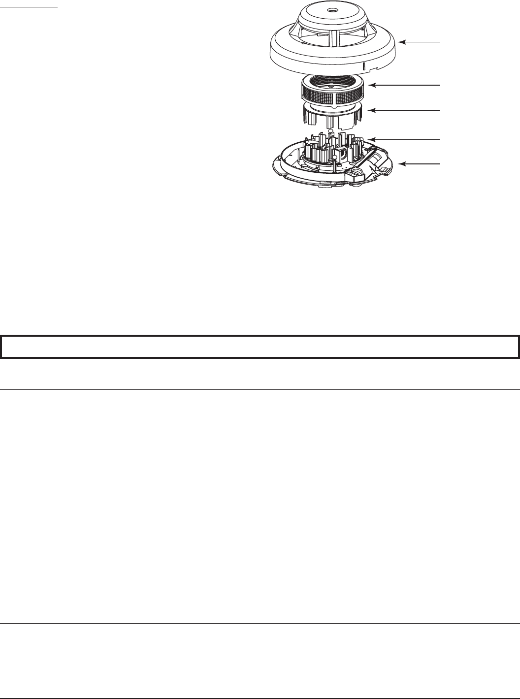
NOTE: Before removing the detector cover, note the position of the thermis-
tors. Make sure the thermistors are not bent over when the housing is
replaced.
1. Remove the detector housing by gently prying the four housing tabs
on the bottom of the base with a small-bladed screwdriver and pull
the housing from the base. Use caution to avoid damaging the
thermistors.
2. Vacuum the screen carefully without removing it.
3. Remove screen assembly, pulling straight out (please see Figure 4).
4. Remove the sensing chamber cover.
5. Clean the sensing chamber by vacuuming or blowing out dust and
particles.
6. Replace the sensing chamber cover, aligning the arrow on the cover
top with the arrow on the printed circuit board.
7. Replace the screen by placing the screen assembly over the sensing
chamber cover and twisting until it snaps into place.
8. Replace the housing by aligning the two triangular slots on the
base with their counterparts on the housing. Gently press the
housing until it locks in place. Check to make sure that the ther-
mistors are in the upright position.
9. Reinstall the detector.
10. Notify the proper authorities that the system is back in operation.
REMOVABLE
HOUSING
BASE
REMOVABLE
SCREEN
SENSING
CHAMBER COVER
SENSING
CHAMBER
S0163-00
Figure 4. Removal of Cover and Screen for Cleaning
Please refer to insert for the Limitations of Fire Alarm Systems