Ademco 8DL5817XT Three Zone Universal Transmitter User Manual 5817XT THREE POINT UNIVERSAL TRANSMITTER
Honeywell International Inc. Three Zone Universal Transmitter 5817XT THREE POINT UNIVERSAL TRANSMITTER
Ademco >
Contents
- 1. Installation Instructions Revised
- 2. Carton Install Info
Installation Instructions Revised
5817XT THREE-POINT UNIVERSAL TRANSMITTER – Installation and Setup Guide
GENERAL INFORMATION
The 5817XT Three-Point Universal Transmitter provides up to three connections for contact loops. Each loop transmits a unique serial number to a
5800 wireless system receiver connected to the system control panel. The Primary Loop’s connection requirements, response and transmission
characteristics are set via DIP switch. (See table.)
SPECIFICATIONS
Dimensions
Length 3.5”
Width 1.6”
Depth 1.2”
(89mm)
(40mm)
(30mm)
Tamper Detection
Enrollment Type
Activates when cover removed
Supervised RF
(Mandatory in UL installations)
Battery Type
Lithium 3V, supplied. Replace with only:
Duracell DL 123
Duracell DL123A
Panasonic CR123A
ADEMCO 466
Contact Loops (3)
Primary loop: DIP switch selectable options
Response time 320mSec – 5mSec, approx.
Aux loops: Closed circuit
Response time 320mSec, approx.
In UL installations, a contact must be installed within 3' of
the transmitter,
with no intervening walls or barriers.
1 Installation
Guidelines
This device is for professional installation only.
•In Residential Fire installations, 5817XT may be connected to
only
one
initiating device. In Residential Burglar Alarm installations, the
transmitter may be connected to multiple initiating devices,
only if
all of these devices serve the same function
(i.e., all devices are
door contacts or all are window contacts).
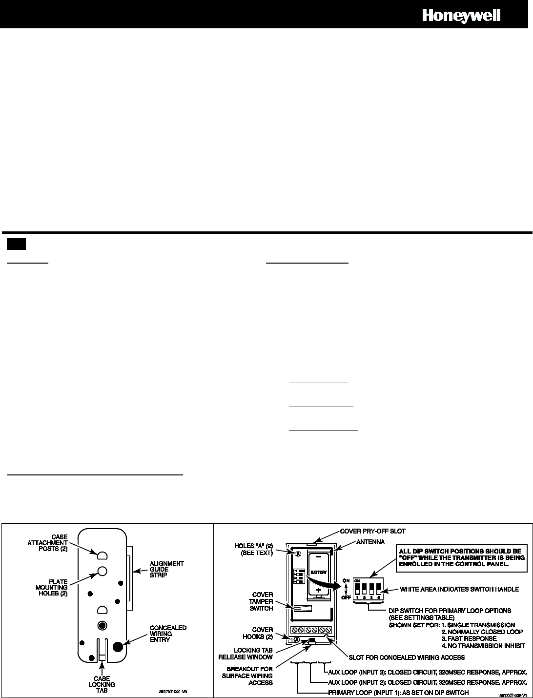
•Use of the included mounting plate is strongly recommended for
ease of removal if the transmitter requires servicing. Holes in the
transmitter’s rear case allow mounting directly to a surface. Holes
are labeled “A”, located top and bottom left in Figure 2.
•BEFORE separating the transmitter from the mounting plate, look at
the concealed wiring entry next to the locking tab on the mounting
plate. Note that the opening aligns with the concealed wiring access
slot on the transmitter’s rear case.
•Perform the Go/No Go test to determine the position for best signal
strength BEFORE mounting the transmitter permanently (see control
panel instructions). Verify best signal strength and reorient or
relocate the transmitter as needed.
•REMOVE the battery from the transmitter after finding the best
location.
Enrolling the transmitter in the control panel
See the control panel’s instructions for more information.
•Make sure all DIP switch positions are OFF during enrollment in the
control panel.
•Make sure to enroll the 5817XT as input type “RF” (Supervised RF).
Mounting and Wiring
1. Remove the transmitter’s top cover. Insert a small flat-blade
screwdriver into the cover pry-off slot seen in Figure 2. Twist the blade
gently until the cover disengages.
2. Disengage the mounting plate from the transmitter’s rear
case. Insert a small flat-blade screwdriver into the locking tab release
window and press it against the locking tab, while sliding the mounting
plate until free. See Figures 1 and 2.
3. Install the mounting plate at the transmitter’s planned location
(optional). Use the flat-head screws supplied.
4. Route the wires
•Concealed wiring: Align the device’s concealed wiring entry with the
wire exit in the wall. Wire exit should not exceed 0.25" diameter.
•Wired contact loop: Feed concealed wiring through the entry
openings, but do not connect the wire to the loop terminals yet.
•Surface wiring entry: Use breakout slots on long sides of case.
5. Attach the case to the mounting plate. Press the case against the
mounting plate and slide until the locking tab clicks into place.
6. Connect loop wiring to the transmitter’s loop terminals, shown in
Figure 2.
Figure 1: Mounting Plate
Figure 2: 5817XT, seen with front cover removed.
EXHIBIT 7A B CFS8DL5817XT / 573F-5817XT
SEE BOTTOM OF NEXT PAGE FOR AGENCY
STATEMENTS
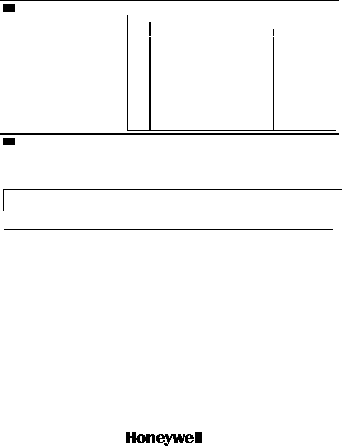
2 DIP Switch Settings
After enrollment in the control panel, set the DIP
switch for the desired primary loop characteristics, as
described in the table at right.
Notes
a. DIP switches may be set by a professional installer
only. They may not be changed by the end user.
b. Due to FCC regulation 15.231(a)(4), DIP switch
position 1 may not be set to ON unless Loop 1 is
used to indicate a type of emergency involving fire,
security or safety of life.
c. Except in the case of the position 4 ON setting, the
Auxiliary loops are not affected by the DIP switch
settings.
d.
For UL installations with fire zones, the position 4
ON setting must not be used.
IMPORTANT: The 5817XT transmitter resets when
a DIP switch is changed. This can take up to one
minute.
SWITCH
P R I M A R Y L O O P O P T I O N S – D I P S W I T C H P O S I T I O N S
SETTING
1 2 3 4
ON
REPEATING
TRANSMISSION
(every 4 sec.)
Upon primary
loop fault
For high-priority
alarm, such as fire.
N.O. CIRCUIT
PRIMARY
LOOP
NORMAL
PRIMARY LOOP
RESPONSE
(Approx. 320mSec
response time)
3 MINUTE, ALL LOOP
TRANSMISSION INHIBIT
After restore of primary loop.
See note d.
This affects all Aux. loops.
Use on often-used doors,
etc. to conserve battery.
OFF
SINGLE
TRANSMISSION
Per primary loop
Change-of-State
N.C. CIRCUIT
PRIMARY
LOOP
FAST
PRIMARY LOOP
RESPONSE
(Approx. 5mSec
response time)
NO
TRANSMISSION
INHIBIT
3 Battery Installation / Replacement
1. Remove the transmitter's cover if it is still in place. See Step 1 under Mounting and Wiring.
2. Observe correct polarity and insert the battery into the battery holder (see Figure 2).
3. To replace the cover, engage the hooks on either side of the locking tab release, and snap shut.
ENROLLMENT NOTE: Wait 30 seconds after battery installation before enrolling the transmitter.
Replace the battery with only Duracell DL 123, Duracell DL123A, Panasonic CR123A or ADEMCO 466.
BATTERY CAUTION
Risk of fire, explosion, and burns. Do not recharge, disassemble, heat above 212°F (100°C), or incinerate.
Dispose of used batteries promptly. Keep away from children.
IMPORTANT:
The 5817XT Transmitter should be tested at least once per week to ensure proper operation.
FEDERAL COMMUNICATIONS COMMISSION STATEMENTS
The user shall not make any changes or modifications to the equipment unless authorized by the Installation Instructions or User's Manual. Unauthorized changes or
modifications could void the user's authority to operate the equipment. Equipment should be installed in accordance with Chapter 2 of ANSI/NFPA 72.
CLASS B DIGITAL DEVICE STATEMENT
This equipment has been tested to FCC requirements and has been found acceptable for use. The FCC requires the following statement for your information:
This equipment generates and uses radio frequency energy and if not installed and used properly, that is, in strict accordance with the manufacturer's instructions,
may cause interference to radio and television reception. It has been type tested and found to comply with the limits for a Class B computing device in accordance
with the specifications in Part 15 of FCC Rules, which are designed to provide reasonable protection against such interference in a residential installation. However,
there is no guarantee that interference will not occur in a particular installation. If this equipment does cause interference to radio or television reception, which can
be determined by turning the equipment off and on, the user is encouraged to try to correct the interference by one or more of the following measures:
• If using an indoor antenna, have a quality outdoor antenna installed.
• Reorient the receiving antenna until interference is reduced or eliminated.
• Move the radio or television receiver away from the receiver/control.
• Move the antenna leads away from any wire runs to the receiver/control.
• Plug the receiver/control into a different outlet so that it and the radio or television receiver are on different branch circuits.
• Consult the dealer or an experienced radio/TV technician for help.
INDUSTRY CANADA CLASS B STATEMENT
This Class B digital apparatus complies with Canadian ICES-003.
Cet appareil numérique de la classe B est conforme à la norme NMB-003 du Canada.
FCC / IC STATEMENT
This device complies with Part 15 of the FCC Rules, and RSS210 of Industry Canada. Operation is subject to the following two conditions: (1) This device may not
cause harmful interference, and (2) This device must accept any interference received, including interference that may cause undesired operation.
Cet appareil est conforme à la partie 15 des règles de la FCC & de RSS 210 des Industries Canada. Son fonctionnement est soumis aux conditions suivantes: (1) Cet
appareil ne doit pas causer d’interférences nuisibles. (2) Cet appareil doit accepter toute interférence reçue y compris les interférences causant une réception
indésirable.
For limitations of the entire alarm system, refer to the installation instructions for the control panel with which this device is used.
WARRANTY Go to: http://www.security.honeywell.com/hsc/resources/wa/
DOCUMENTATION AND ONLINE SUPPORT Go to: http://www.security.honeywell.com/hsc/resources/MyWebTech/
Ê800-18506CŠ
800-18506 6/14 Rev. B
2 Corporate Center Drive, Suite 100
P.O. Box 9040, Melville, NY 11747
Copyright 2014 Honeywell International Inc.
www.honeywell.com/security