Ademco 8DL5818-1 Security Remote Transmitter User Manual N7022V3 draft
Honeywell International Inc. Security Remote Transmitter N7022V3 draft
Ademco >
USERS MANUAL WITH FCC ID AND PART 15 STATMENT
N7022V3 4/05 Rev. A
5818 Recessed Door Transmitter
INSTALLATION AND SETUP GUIDE
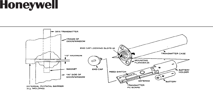
TYPICAL INSTALLATION
GENERAL INFORMATION
The 5818 Recessed Door Transmitter is a
reed switch, magnetic-contact sensor that
provides concealed protection for a door.
It is intended for use only with alarm
systems that support 5800 series devices.
The transmitter is powered by long-life
lithium battery that is easily replaceable
when a low battery is indicated by the
control.
PROGRAMMING THE ID NUMBER
Each 5818 has its own unique
identification code (serial number)
permanently assigned during manu-
facture.
You must “enroll” the transmitter’s ID
during installation of the alarm system.
5818 transmitters must be enrolled as
"RF" (supervised RF) Type (mandatory for
UL installations).
PRELIMINARY CONSIDERATIONS
Read all of this and the next section
before installing the unit.
1. Select a location for the transmitter
on the frame of the door (never on
the hinged edge) to be protected.
• Do not use on metal frame doors.
• The transmitter will require a 7/8“
diameter hole in the edge of the
frame, at least 5” deep and its
magnet will need a 1/2” diameter hole
in the edge of the door at least 1-3/4”
deep.
BEFORE DRILLING ANY HOLES, SEE
STEP 2 BELOW AND READ ALL
OFMOUNTING.
• The preferred direction of mounting is
vertical, although the 5818 may be
mounted in any direction if
satisfactory reception of its
transmissions is obtained.
• A physical barrier (e.g., a molding
strip on the door frame) should be
present to protect against defeat of
the contact from outside the
premises.
2. Before drilling any holes, tape the
transmitter and magnet in their
approximate locations (with battery
installed and unit together as described
under BATTERY INSTALLATION/
REPLACEMENT (below) and conduct
Go/No Go tests (refer to control panel’s
instructions) to verify adequate signal
strength. Reorient or relocate trans-
mitter if necessary.
• Make sure that no more than 1/2”
gap exists between the faces of the
transmitter and magnet cases when
they are installed and set.
• When installed, an alarm signal must
be obtained before a clear space of
2” is reached as the door is opened.
MOUNTING
1. Mark the selected location for the
transmitter on the frame of the door.
ÊN7022V3GŠ
N7022V3 4/05 Rev. A
165 Eileen Way, Syosset, New York 11791
Copyright © 2004 Honeywell International Inc.
www.honeywell.com/security
2. Mark the location for the magnet on
the door, directly opposite the
transmitter location.
Caution: Before drilling any holes,
make sure that successful Go/No Go
transmission/reception tests have been
conducted (see previous section).
3. Drill holes at the locations marked for
the transmitter (7/8” diameter, at least
5” deep) and magnet (1/2” diameter, at
least 1-3/4” deep).
4. Insert the transmitter and magnet
cases into their respective holes, so
that their ends are flush with the
surface.
• DO NOT hammer in place with hard
blows. If necessary, tap gently with a
rubber mallet or wood block.
• The transmitter case may be secured
by two screws via the holes in its
mounting flanges, or the flanges can
be snapped off by scoring around
them first with a sharp knife.
• If necessary, either case may be
secured with a suitable adhesive.
A closure plug is supplied to cover an
empty hole if the transmitter is ever
relocated.
BATTERY INSTALLATION OR
REPLACEMENT
1. Remove the transmitter’s end cap by
inserting the flat blade of a small
screwdriver in the cap’s slot and turning
slightly counterclockwise.
2. Slide the transmitter PC board
assembly out of its case, taking care
not to bend the antenna during this step
or later.
3. Remove the old battery, if replacing it.
4. Observe correct polarity and insert
the fresh battery into the battery holder
(+ and – polarity indications are inside).
See diagram.
5. Slide the PC board assembly back
into its case, battery end first (the reed
switch end must be toward the cap).
6. Replace the end cap. Line up the
projections on the cap with the
openings at the edge of the case. Press
the cap gently against the PC board
and turn the cap (via its slot) slightly
clockwise, thereby locking it in place.
BATTERY CAUTION: Risk of fire, explosion,
and burns. Do not recharge, disassemble,
heat above 212ºF (100ºC) or incinerate.
Dispose of used batteries promptly. Keep
away from children.
SPECIFICATIONS
Dimensions (Approximate) Transmitter: 13/16” (21mm) Diameter x 4-7/8” (124mm) Long
Magnet: 1/2” (13mm) Diameter x 1-3/4” (45mm) Long
Battery: 3V Lithium. Replace battery only with:
Panasonic CR123A, Duracell DL123A, Sanyo CR123A, Varta CR123A, or Ademco 466.
TO THE INSTALLER
Regular maintenance and inspection (at least annually) by the installer and frequent testing by the user are vital to
continuous satisfactory operation of any alarm system.
The installer should assume the responsibility of developing and offering a regular maintenance program to the
user, as well as acquainting the user with the proper operation and limitations of the alarm system and its
component parts. Recommendations must be included for a specific program of frequent testing (at least weekly)
to insure the system’s operation at all times.
REFER TO THE INSTALLATION INSTRUCTIONS FOR THE RECEIVER/CONTROL WITH WHICH THIS
DEVICE IS USED, FOR WARRANTY IFFORMATION AND FOR DETAILS REGARDING LIMITATIONS OF THE
ENTIRE ALARM SYSTEM.
FCC ID: CFS8DL5818-1
This device complies with Part 15 of the FCC Rules. Operation is subject to the following two
conditions: (1) This device may not cause harmful interference (2) This device must accept any
interference received, including interference that may cause undesired operation.
CANADA: 573F-58181