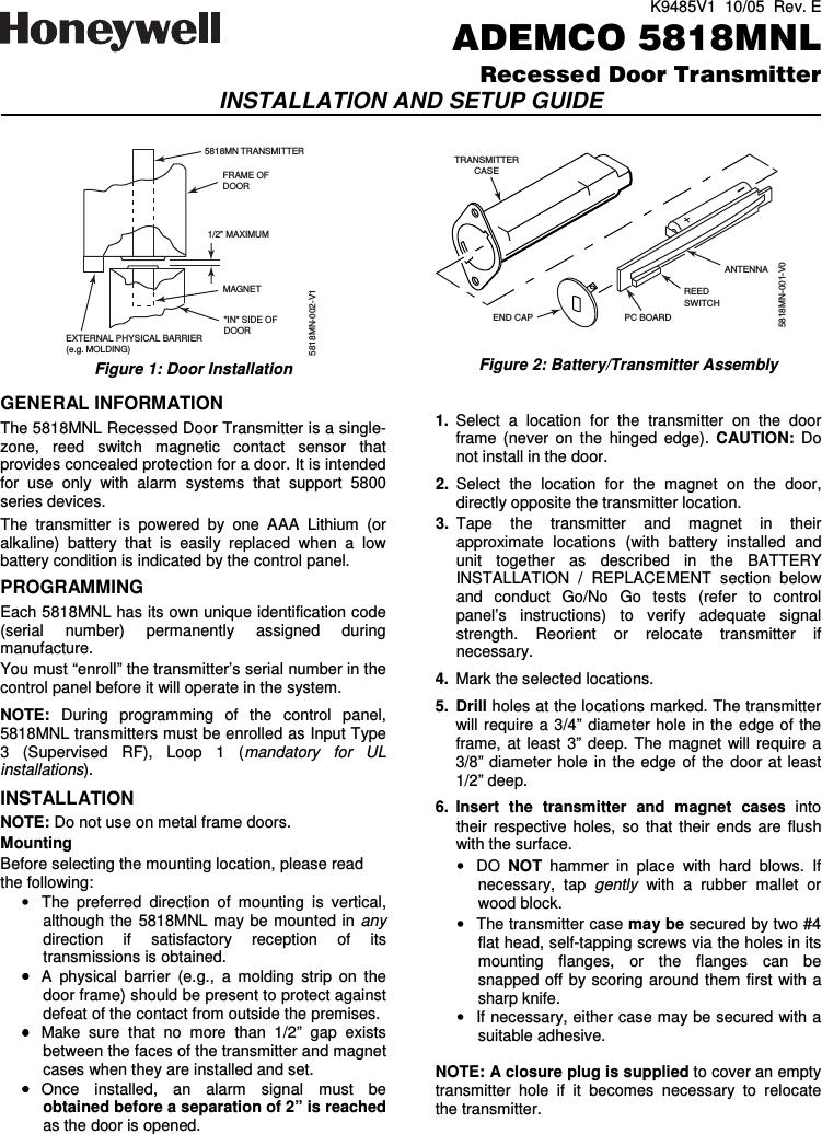
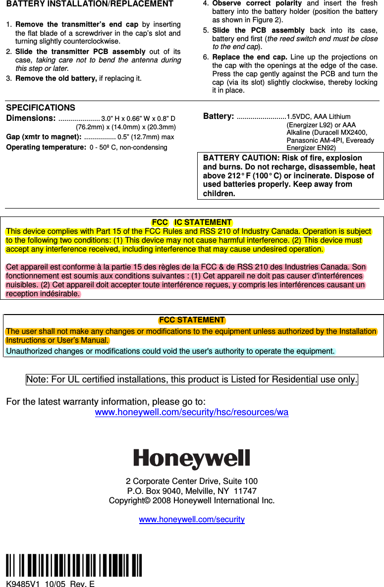
Ademco 8DL5818MNL Recessed Door Transmitter User Manual K9485V1 RevE

Honeywell International Inc. Recessed Door Transmitter K9485V1 RevE

Users Manual

K9485V1  10/05  Rev. E ADEMCO 5818MNLRecessed Door TransmitterINSTALLATION AND SETUP GUIDE  EXTERNAL PHYSICAL BARRIER(e.g. MOLDING)1/2" MAXIMUMMAGNET"IN" SIDE OFDOOR5818MN TRANSMITTER5818MN-002-V1FRAME OFDOOR Figure 1: Door Installation  GENERAL INFORMATION The 5818MNL Recessed Door Transmitter is a single-zone,  reed  switch  magnetic  contact  sensor  that provides concealed protection for a door. It is intended for  use  only  with  alarm  systems  that  support  5800 series devices. The  transmitter  is  powered  by  one  AAA  Lithium  (or alkaline)  battery  that  is  easily  replaced  when  a  low battery condition is indicated by the control panel. PROGRAMMING  Each 5818MNL has its own unique identification code (serial  number)  permanently  assigned  during manufacture. You must “enroll” the transmitter’s serial number in the control panel before it will operate in the system.  NOTE:  During  programming  of  the  control  panel, 5818MNL transmitters must be enrolled as Input Type 3  (Supervised  RF),  Loop  1  (mandatory  for  UL installations). INSTALLATION  NOTE: Do not use on metal frame doors. Mounting Before selecting the mounting location, please read the following: •  The  preferred  direction  of  mounting  is  vertical, although the 5818MNL may be  mounted  in any direction  if  satisfactory  reception  of  its transmissions is obtained.  •••• A  physical  barrier  (e.g.,  a  molding  strip  on  the door frame) should be present to protect against defeat of the contact from outside the premises. •••• Make  sure  that  no  more  than  1/2”  gap  exists between the faces of the transmitter and magnet cases when they are installed and set. •••• Once  installed,  an  alarm  signal  must  be obtained before a separation of 2” is reached as the door is opened.    TRANSMITTERCASEANTENNAEND CAPREEDSWITCHPC BOARD5818MN-001-V0  Figure 2: Battery/Transmitter Assembly  1.  Select  a  location  for  the  transmitter  on  the  door frame  (never  on the  hinged  edge).  CAUTION: Do not install in the door. 2.  Select  the  location  for  the  magnet  on  the  door, directly opposite the transmitter location.  3.  Tape  the  transmitter  and  magnet  in  their approximate  locations  (with  battery  installed  and unit  together  as  described  in  the  BATTERY INSTALLATION  /  REPLACEMENT  section  below and  conduct  Go/No  Go  tests  (refer  to  control panel’s  instructions)  to  verify  adequate  signal strength.  Reorient  or  relocate  transmitter  if necessary. 4.  Mark the selected locations.  5.  Drill holes at the locations marked. The transmitter will require  a  3/4” diameter hole  in  the edge of the frame,  at  least  3”  deep.  The  magnet  will  require  a 3/8” diameter hole in the edge of  the  door at least 1/2” deep. 6.  Insert  the  transmitter  and  magnet  cases  into their  respective  holes, so  that  their  ends  are  flush with the surface. •  DO  NOT  hammer  in  place  with  hard  blows.  If necessary,  tap  gently  with  a  rubber  mallet  or wood block. •  The transmitter case may be secured by two #4 flat head, self-tapping screws via the holes in its mounting  flanges,  or  the  flanges  can  be snapped off  by scoring  around them first  with a sharp knife. •  If necessary, either case may be secured with a suitable adhesive.  NOTE: A closure plug is supplied to cover an empty transmitter  hole  if  it  becomes  necessary  to  relocate the transmitter.
BATTERY INSTALLATION/REPLACEMENT  1.  Remove  the  transmitter’s  end  cap  by  inserting the flat blade of a screwdriver in the cap’s slot and turning slightly counterclockwise. 2.  Slide  the  transmitter  PCB  assembly  out  of  its case, taking  care  not  to  bend  the  antenna  during this step or later. 3.  Remove the old battery, if replacing it. 4.  Observe  correct  polarity  and  insert  the  fresh battery  into  the  battery  holder  (position  the  battery as shown in Figure 2). 5.  Slide  the  PCB  assembly  back  into  its  case, battery end first (the reed switch end must be close to the end cap). 6.  Replace  the  end  cap.  Line  up  the  projections  on the cap with the openings at the edge of the case. Press the cap gently against the PCB  and turn the cap (via its  slot) slightly  clockwise,  thereby  locking it in place.   SPECIFICATIONS Dimensions: .....................3.0” H x 0.66” W x 0.8” D  (76.2mm) x (14.0mm) x (20.3mm) Gap (xmtr to magnet):  ................0.5” (12.7mm) max Operating temperature:0 - 50º C, non-condensing  Battery: .........................1.5VDC, AAA Lithium (Energizer L92) or AAA Alkaline (Duracell MX2400,  Panasonic AM-4PI, Eveready Energizer EN92)  BATTERY CAUTION: Risk of fire, explosion and burns. Do not recharge, disassemble, heat above 212° F (100° C) or incinerate. Dispose of used batteries properly. Keep away from children.    FCC   IC STATEMENT This device complies with Part 15 of the FCC Rules and RSS 210 of Industry Canada. Operation is subject to the following two conditions: (1) This device may not cause harmful interference. (2) This device must accept any interference received, including interference that may cause undesired operation.   Cet appareil est conforme à la partie 15 des règles de la FCC & de RSS 210 des Industries Canada. Son fonctionnement est soumis aux conditions suivantes : (1) Cet appareil ne doit pas causer d'interférences nuisibles. (2) Cet appareil doit accepter toute interférence reçues, y compris les interférences causant un reception indésirable.    FCC STATEMENT The user shall not make any changes or modifications to the equipment unless authorized by the Installation Instructions or User’s Manual. Unauthorized changes or modifications could void the user's authority to operate the equipment.     Note: For UL certified installations, this product is Listed for Residential use only.   For the latest warranty information, please go to: www.honeywell.com/security/hsc/resources/wa    2 Corporate Center Drive, Suite 100 P.O. Box 9040, Melville, NY  11747 Copyright© 2008 Honeywell International Inc.  www.honeywell.com/security       ÊK9485V1mŠ  K9485V1  10/05  Rev. E

Navigation menu