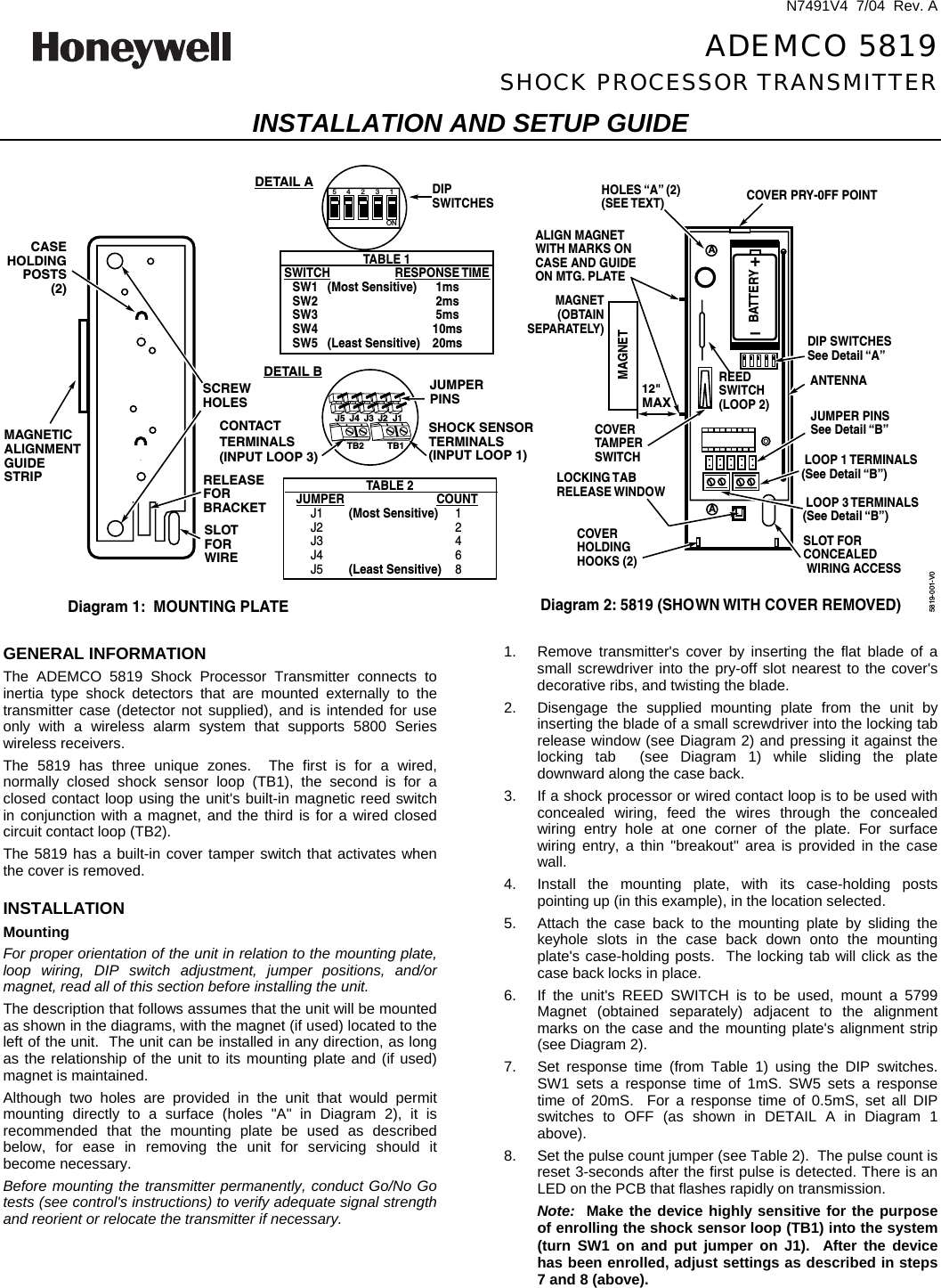
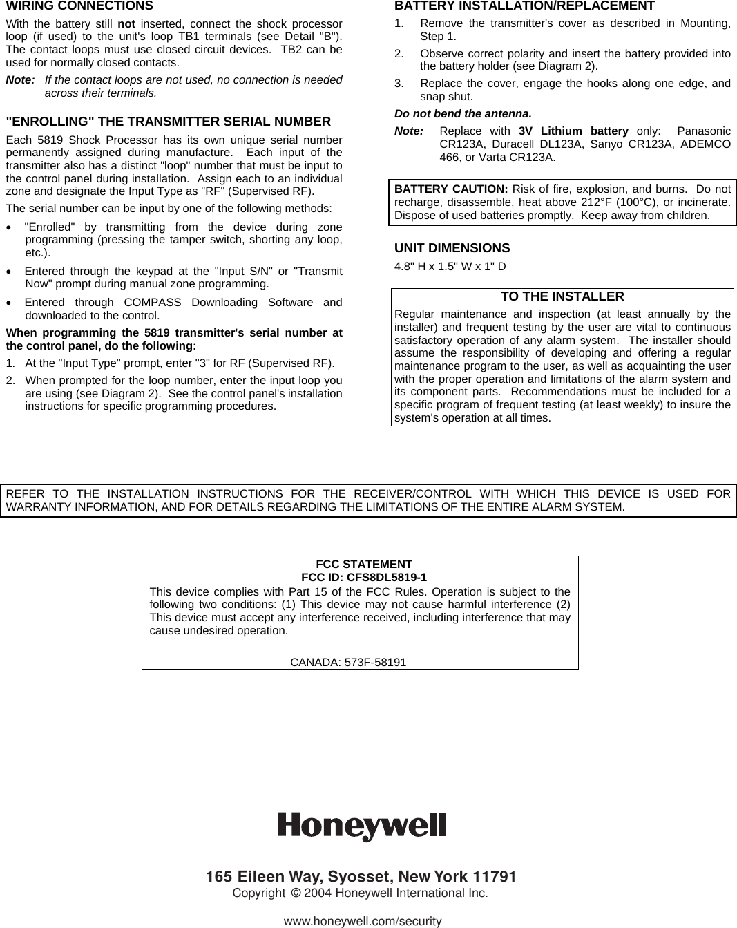
Ademco 8DL5819-1 Security Remote Transmitter User Manual N7491V4 RevA

Honeywell International Inc. Security Remote Transmitter N7491V4 RevA

users manual with FCC Part 15 statment and FCC ID

 N7491V4  7/04  Rev. A  ADEMCO 5819 SHOCK PROCESSOR TRANSMITTER INSTALLATION AND SETUP GUIDE  A+–BATTERYREEDSWITCH(LOOP 2)COVER PRY-0FF POINTALIGN MAGNETWITH MARKS ONCASE AND GUIDEON MTG. PLATEMAGNET (OBTAIN SEPARATELY)LOOP 1 TERMINALS(See Detail “B”)LOCKING TABRELEASE WINDOWCOVERHOLDINGHOOKS (2)COVERTAMPERSWITCHHOLES “A” (2)(SEE TEXT)ANTENNADIP SWITCHESSee Detail “A”DIPSWITCHESJUMPER PINSSee Detail “B”SLOT FORCONCEALEDWIRING ACCESSAMAGNETDiagram 2: 5819 (SHOWN WITH COVER REMOVED)12"MAX12345ONTB2 TB1MAGNETICALIGNMENTGUIDESTRIP RELEASE FORBRACKETCASEHOLDINGPOSTS(2)SLOT FOR WIRESCREWHOLESDiagram 1:  MOUNTING PLATETABLE 1SWITCH RESPONSE TIMESW1   (Most Sensitive) 1msSW2 2msSW3 5msSW4 10msSW5   (Least Sensitive) 20msJUMPERPINSSHOCK SENSORTERMINALS(INPUT LOOP 1)TABLE 2JUMPER COUNTJ1        (Most Sensitive) 1J2 2J3 4J4 6J5        (Least Sensitive) 8J5 J4 J3 J2 J1DETAIL BDETAIL ACONTACTTERMINALS(INPUT LOOP 3)LOOP 3 TERMINALS(See Detail “B”)5819-001-V0  GENERAL INFORMATION The ADEMCO 5819 Shock Processor Transmitter connects to inertia type shock detectors that are mounted externally to the transmitter case (detector not supplied), and is intended for use only with a wireless alarm system that supports 5800 Series wireless receivers. The 5819 has three unique zones.  The first is for a wired, normally closed shock sensor loop (TB1), the second is for a closed contact loop using the unit's built-in magnetic reed switch in conjunction with a magnet, and the third is for a wired closed circuit contact loop (TB2).   The 5819 has a built-in cover tamper switch that activates when the cover is removed.  INSTALLATION Mounting For proper orientation of the unit in relation to the mounting plate, loop wiring, DIP switch adjustment, jumper positions, and/or magnet, read all of this section before installing the unit. The description that follows assumes that the unit will be mounted as shown in the diagrams, with the magnet (if used) located to the left of the unit.  The unit can be installed in any direction, as long as the relationship of the unit to its mounting plate and (if used) magnet is maintained. Although two holes are provided in the unit that would permit mounting directly to a surface (holes "A" in Diagram 2), it is recommended that the mounting plate be used as described below, for ease in removing the unit for servicing should it become necessary. Before mounting the transmitter permanently, conduct Go/No Go tests (see control's instructions) to verify adequate signal strength and reorient or relocate the transmitter if necessary. 1.  Remove transmitter's cover by inserting the flat blade of a small screwdriver into the pry-off slot nearest to the cover's decorative ribs, and twisting the blade. 2.  Disengage the supplied mounting plate from the unit by inserting the blade of a small screwdriver into the locking tab release window (see Diagram 2) and pressing it against the locking tab  (see Diagram 1) while sliding the plate downward along the case back. 3.  If a shock processor or wired contact loop is to be used with concealed wiring, feed the wires through the concealed wiring entry hole at one corner of the plate. For surface wiring entry, a thin "breakout" area is provided in the case wall. 4.  Install the mounting plate, with its case-holding posts pointing up (in this example), in the location selected. 5.  Attach the case back to the mounting plate by sliding the keyhole slots in the case back down onto the mounting plate's case-holding posts.  The locking tab will click as the case back locks in place. 6.  If the unit's REED SWITCH is to be used, mount a 5799 Magnet (obtained separately) adjacent to the alignment marks on the case and the mounting plate's alignment strip (see Diagram 2). 7.  Set response time (from Table 1) using the DIP switches. SW1 sets a response time of 1mS. SW5 sets a response time of 20mS.  For a response time of 0.5mS, set all DIP switches to OFF (as shown in DETAIL A in Diagram 1 above).   8.  Set the pulse count jumper (see Table 2).  The pulse count is reset 3-seconds after the first pulse is detected. There is an LED on the PCB that flashes rapidly on transmission. Note:  Make the device highly sensitive for the purpose of enrolling the shock sensor loop (TB1) into the system (turn SW1 on and put jumper on J1).  After the device has been enrolled, adjust settings as described in steps 7 and 8 (above).
WIRING CONNECTIONS With the battery still not inserted, connect the shock processor loop (if used) to the unit's loop TB1 terminals (see Detail "B").  The contact loops must use closed circuit devices.  TB2 can be used for normally closed contacts. Note:  If the contact loops are not used, no connection is needed across their terminals.  "ENROLLING" THE TRANSMITTER SERIAL NUMBER Each 5819 Shock Processor has its own unique serial number permanently assigned during manufacture.  Each input of the transmitter also has a distinct "loop" number that must be input to the control panel during installation.  Assign each to an individual zone and designate the Input Type as "RF" (Supervised RF). The serial number can be input by one of the following methods: •  "Enrolled" by transmitting from the device during zone programming (pressing the tamper switch, shorting any loop, etc.). •  Entered through the keypad at the "Input S/N" or "Transmit Now" prompt during manual zone programming. •  Entered through COMPASS Downloading Software and downloaded to the control.   When programming the 5819 transmitter's serial number at the control panel, do the following: 1.  At the "Input Type" prompt, enter "3" for RF (Supervised RF). 2.  When prompted for the loop number, enter the input loop you are using (see Diagram 2).  See the control panel's installation instructions for specific programming procedures. BATTERY INSTALLATION/REPLACEMENT 1.  Remove the transmitter's cover as described in Mounting, Step 1. 2.  Observe correct polarity and insert the battery provided into the battery holder (see Diagram 2).   3.  Replace the cover, engage the hooks along one edge, and snap shut. Do not bend the antenna. Note:  Replace with 3V Lithium battery only:  Panasonic CR123A, Duracell DL123A, Sanyo CR123A, ADEMCO 466, or Varta CR123A.  BATTERY CAUTION: Risk of fire, explosion, and burns.  Do not recharge, disassemble, heat above 212°F (100°C), or incinerate.  Dispose of used batteries promptly.  Keep away from children.  UNIT DIMENSIONS 4.8" H x 1.5" W x 1" D  TO THE INSTALLER Regular maintenance and inspection (at least annually by the installer) and frequent testing by the user are vital to continuous satisfactory operation of any alarm system.  The installer should assume the responsibility of developing and offering a regular maintenance program to the user, as well as acquainting the user with the proper operation and limitations of the alarm system and its component parts.  Recommendations must be included for a specific program of frequent testing (at least weekly) to insure the system's operation at all times.     REFER TO THE INSTALLATION INSTRUCTIONS FOR THE RECEIVER/CONTROL WITH WHICH THIS DEVICE IS USED FOR WARRANTY INFORMATION, AND FOR DETAILS REGARDING THE LIMITATIONS OF THE ENTIRE ALARM SYSTEM.   FCC STATEMENT FCC ID: CFS8DL5819-1 This device complies with Part 15 of the FCC Rules. Operation is subject to the following two conditions: (1) This device may not cause harmful interference (2) This device must accept any interference received, including interference that may cause undesired operation.                                              CANADA: 573F-58191           165 Eileen Way, Syosset, New York 11791Copyright © 2004 Honeywell International Inc.www.honeywell.com/security
ÊN7491V4qŠ N7491V4  7/04  Rev. A

Navigation menu