Ademco 8DL5819S Shock Processor Transmitter User Manual
Honeywell International Inc. Shock Processor Transmitter
Ademco >
User manual
5819S Wireless Shock Sensor and Transmitter – Installation Instructions
The 5819S includes an omni-directional, built-in shock sensor, and is designed to protect window and
door surroundings. Use this Shock Sensor and Transmitter with alarm systems that support Honeywell
5800 Series wireless devices.
Typical shock protection area: 6 - 8 feet / 3 - 4 foot radius (1.8m – 2.44m / 0.91m – 1.23m radius);
The coverage area can vary depending on the mounting surface.
The device supports three unique zones or “loops”:
Loop 1: Normally Open, built-in shock sensor*
Loop 2: Normally closed, built in reed switch, used with the included magnet
Loop 3: Externally wired, closed-circuit contact loop connected to the Terminal Block
*Note: This device features the option to enable Loop 1 to report both shock and reed switch
faults to the panel on a single zone (see Enroll and Program section for details).
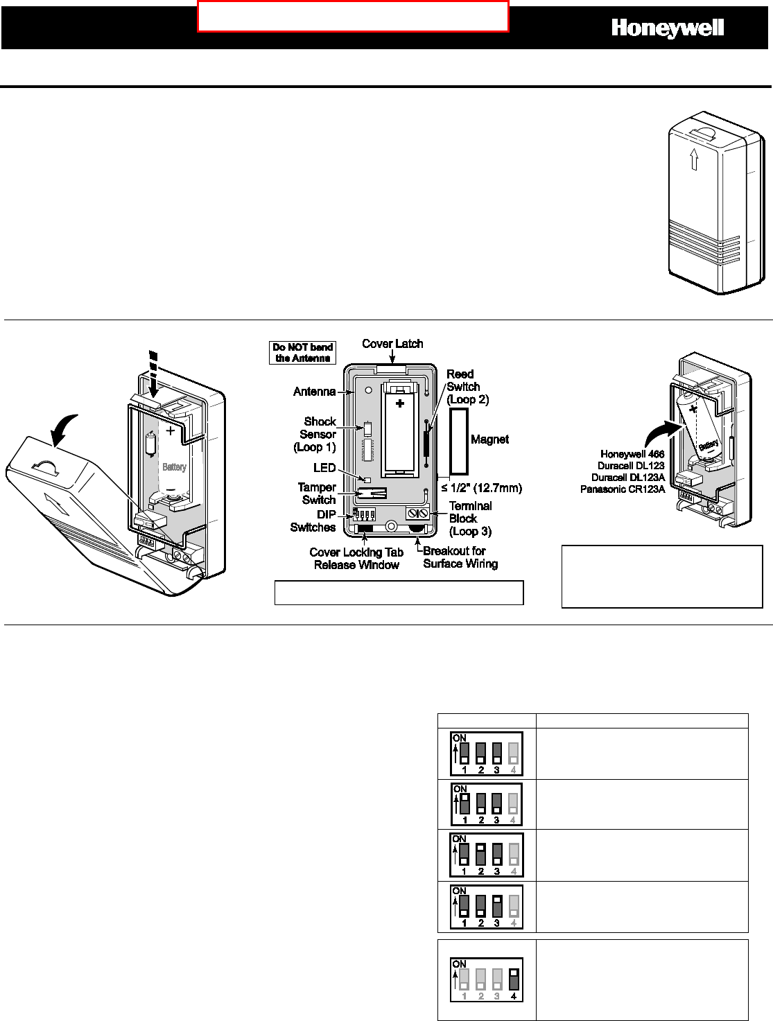
Open the Sensor
Install the Battery
BATTERY CAUTION: Risk of fire,
explosion, and burns. Do not recharge,
disassemble, heat above 212°F (100°C), or
incinerate. Dispose of used batteries
properly. Keep away from children.
Enroll and Program
1. Install the battery and ensure all the DIP Switches are
OFF (Highest Sensitivity setting).
2. Assign an individual zone number to each loop used* and
assign the zones as Input Type = 3 (Supervised RF).
*Note: To set Loop 1 to report both shock and reed switch
faults on a single zone, enroll Loop 1 (do not enroll Loop 2),
and set DIP Switch 4 ON after enrollment.
3. Activate any of the device loops (see loop descriptions
above) to transmit the device serial number to the control.
• For Loop 1, trigger the shock sensor by shaking the
device, or create a shock near the mounted device.
• For Loop 2, move the magnet close to and away from
the reed switch to trigger it.
• For Loop 3, Open and close the contact according to its
instructions.
4. Trigger again to complete enrollment.
The LED will flash rapidly to indicate the device is
transmitting to the control.
Alternatively, enter the device serial number manually
when prompted for the information.
DIP Switch Settings
After enrollment, test and adjust the device sensitivity
until the desired setting is achieved. (Refer to the
Test section.)
DIP SWITCH
SETTING
Most Sensitive (use this setting for
enrollment)
High Sensitivity
Medium Sensitivity
Low Sensitivity
*Set ON - Loop 1 reports both shock
and reed switch faults on a single
zone
Set OFF – Loop 1 reports shock
only
Do NOT Remove the PC Board from the back case
PRELIMINARY DRAFT II’s – 06/09/15
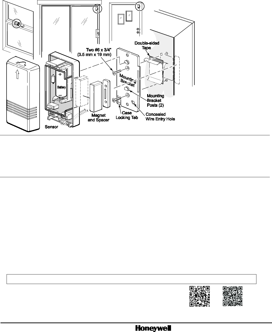
Mount the Sensor
After enrolling and before
mounting permanently,
conduct Go/No Go tests (see
the control's instructions) to
verify adequate signal
strength. Reorient or relocate
the device if necessary.
The device can be mounted in
any direction for shock
sensing.
If using the magnet, install it
within 1/2” (12.7mm) of the
device as shown.
Test
Use a hard tool to carefully
simulate shock impacts on or
near the area where the
device is mounted. The LED
lights each time the shock
vibrations trip the device.
Adjust the device sensitivity as
needed for the application.
Specifications
Power: 1 x 3 V , Lithium Battery (included); Panasonic CR123A, Duracell DL123 or DL123A, Honeywell 466
Operating Temperature: 14° to 131° F / -10° to 55° C (Agency Compliance 32° to 120° F / 0° to 49° C)
Relative Humidity: Up to 95% (Agency Compliance up to 93%); non-condensing
Dimensions: 3.05” H x 1.54” W x 1” D (77.47mm H x 39.12mm W x 25.4mm D)
Product must be tested at least once each year.
Approval Listings
FCC part 15, Class B verified
IC, RSS-210, Class B verified
ETL
FEDERAL COMMUNICATIONS COMMISSION & INDUSTRY CANADA STATEMENTS
The user shall not make any changes or modifications to the equipment unless authorized by the Installation Instructions or User's Manual. Unauthorized changes or modifications could void the user's
authority to operate the equipment.
CLASS B DIGITAL DEVICE STATEMENT This equipment has been tested to FCC requirements and has been found acceptable for use. The FCC requires the following statement for your
information: This equipment generates and uses radio frequency energy and if not installed and used properly, that is, in strict accordance with the manufacturer's instructions, may cause interference to
radio and television reception. It has been type tested and found to comply with the limits for a Class B computing device in accordance with the specifications in Part 15 of FCC Rules, which are designed
to provide reasonable protection against such interference in a residential installation. However, there is no guarantee that interference will not occur in a particular installation. If this equipment does cause
interference to radio or television reception, which can be determined by turning the equipment off and on, the user is encouraged to try to correct the interference by one or more of the following measures:
• If using an indoor antenna, have a quality outdoor antenna installed.
• Reorient the receiving antenna until interference is reduced or eliminated.
• Move the radio or television receiver away from the receiver/control.
• Move the antenna leads away from any wire runs to the receiver/control.
• Plug the receiver/control into a different outlet so that it and the radio or television receiver are on different branch circuits.
• Consult the dealer or an experienced radio/TV technician for help.
INDUSTRY CANADA CLASS B STATEMENT
This Class B digital apparatus complies with Canadian ICES-003.
Cet appareil numérique de la classe B est conforme à la norme NMB-003 du Canada.
FCC / IC STATEMENT
This device complies with Part 15 of the FCC Rules, and RSS-210 of Industry Canada. Operation is subject to the following two conditions: (1) This device may not cause harmful interference, and (2) This
device must accept any interference received, including interference that may cause undesired operation.
Cet appareil est conforme à la partie 15 des règles de la FCC & de RSS-210 des Industries Canada. Son fonctionnement est soumis aux conditions suivantes: (1) Cet appareil ne doit pas causer
d’interférences nuisibles. (2) Cet appareil doit accepter toute interférence reçue y compris les interférences causant une reception indésirable.
Support and Warranty
REFER TO THE INSTALLATION INSTRUCTIONS FOR THE CONTROL WITH WHICH THIS DEVICE IS USED, FOR DETAILS REGARDING
LIMITATIONS OF THE ENTIRE ALARM SYSTEM.
For the latest documentation and online support information, please go to:
https://mywebtech.honeywell.com/
For the latest warranty information, please go to:
www.honeywell.com/security/hsc/resources/wa
MyWebTech
Warranty
2014 Honeywell International Inc. Honeywell is a registered trademarks of Honeywell International Inc.
All other trademarks are the properties of their respective owners. All rights reserved.
Ê800-19771bŠ
P/N 800-19771 06/15 Rev A
2 Corporate Center Drive, Suite 100
P.O. Box 9040, Melville, NY 11747
www.honeywell.com/security