Ademco 8DL5820 door window security transmitter User Manual K9232 ii
Honeywell International Inc. door window security transmitter K9232 ii
Ademco >
Contents
- 1. II with FCC PART 15 Statement
- 2. Users Manual
II with FCC PART 15 Statement
K9232..12/02
5820
®
Door/Window Contact Transmitter
INSTALLATION AND SETUP GUIDE
GENERAL INFORMATION
Use the 5820 Slim-Line Door/Window contact
transmitter only with alarm systems that
support 5800 Series wireless devices. The 5820
Transmitter has its own unique serial number
permanently assigned during manufacture.
The same serial number must be “learned” into
the control panel prior to the transmitter’s
usage. Refer to the control panel’s installation
instructions for programming details.
Note:
During programming of the control
panel, 5820 transmitters shall be treated as
"RF" (i.e., supervised RF) Type.
The 5820 is assigned as one zone.
TAMPER PROTECTION
Front and back case tamper is provided using
the same switch. The front case tamper is
always enabled. Adding the third screw as
shown in Figure 2 enables the back case
tamper.
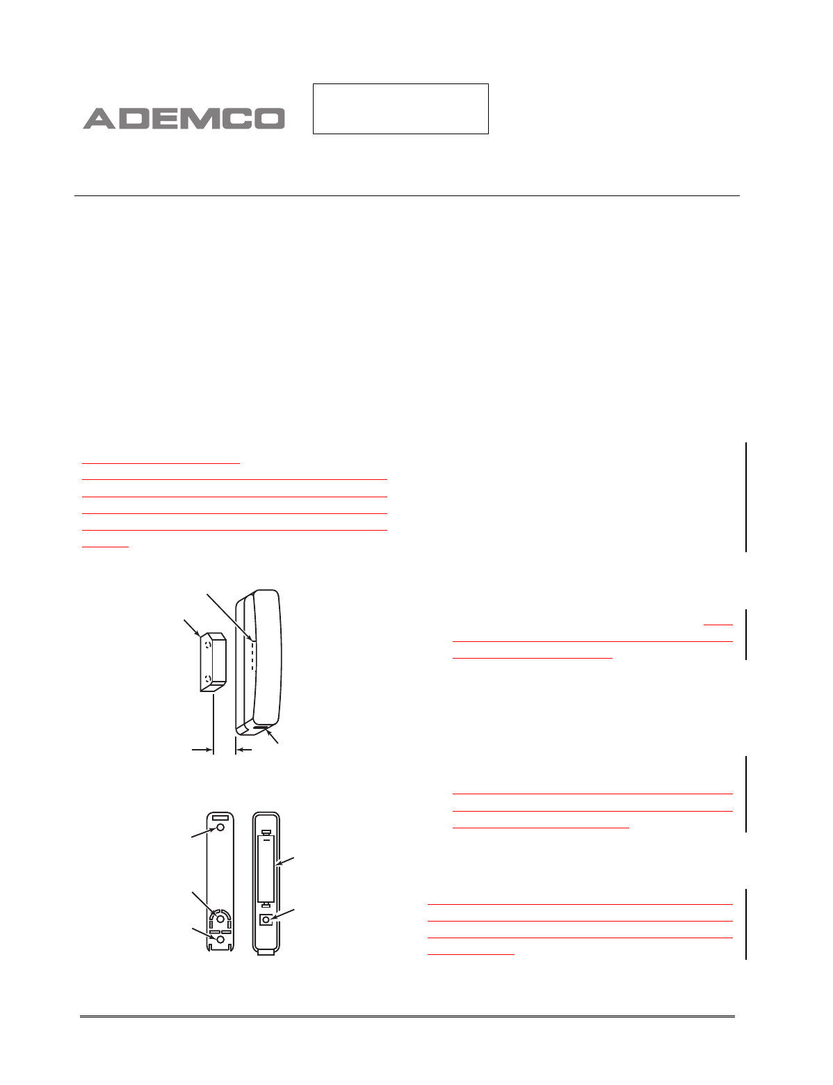
APPROXIMATE LOCATION
OF REED SWITCH
MAGNET
PRY OPEN
SLOT
GAP
.5" MAX
5820-001-V0
Figure 1. 5820 (Typical Installation Arrangement)
+
MOUNTING
HOLE
MOUNTING
HOLE
TAMPER
PROTECTION
5820-002-V0
BATTERY
TAMPER
SWITCH
Figure 2. 5820 Mounting/Battery Location
MOUNTING
The description that follows assumes that the
transmitter will be mounted as shown in
Figure 1, with the magnet located adjacent to
the unit's left side. The transmitter may,
however, be installed in any direction, as long
as the relationship of the unit to the magnet is
maintained as shown in Figure 1.
Observe polarity and install battery supplied
between the contacts in the case as shown in
figure 2. Snap-shut the two halves of the
transmitter case.
1. Temporarily mount the 5820 using the
double-backed tape supplied by removing
the adhesive protective cover from one side
of the tape at a time.
Note:
Before mounting the transmitter
permanently, conduct Go/No Go tests (see
control's instructions) to verify adequate signal
strength and reorient or relocate the transmitter
if necessary.
2. If the Go/No Go test was ok, remove the
transmitter's cover by inserting the flat
blade of a small screwdriver into the- slot
at one end of the unit as shown in Figure 1,
and pulling the cover up.
3. Install mounting screws in the two outside
mounting holes as shown in Figure 2.
4. If the case-back tamper switch will be
used, install a third screw in the middle
hole.
5. Mount the magnet (supplied) adjacent to
the two vertical positioning lines on the
case side (see Figure 1). The gap can be
one-half an inch maximum.
6. To reinstall the cover, position it so that it
covers the mounted case back, and snap-
shut.
Notes: 1)
Do NOT attempt to remove the PCB
from the plastic cover for any reason. 2) The
two case halves can only be fitted together in
one direction.
PRELIMINARY
12/12/02..tp

¬.l
K9232 12/02
BATTERY INSTALLATION/REPLACEMENT
Replace battery only with same or equivalent
type. Dispose of used batteries according to
the battery manufacturer’s instruction.
1. Remove the transmitter's cover (if it is
not already off) as described in Mounting
Step 2.
2. Observe correct polarity and insert the
battery provided into the battery retainer
clips as shown in Figure 2.
Note: Replace battery only with type
specified in the following specifications.
SPECIFICATIONS
Contact Gap: 0.5 inch maximum
Dimensions: 0.5” (12.7mm) x 3.0” (76.2mm) x
0.8” (20.3mm)
Battery: 1.5V, AAA, Panasonic, Sanyo, or
Duracell.
FCC STATEMENT
FCC ID: CFS8DL5820MN
This device complies with Part 15 of the FCC Rules. Operation is subject to the following two
conditions: (1) This device may not cause harmful interference, and (2), this device must accept any
interference received, including interference that may cause undesired operation.
REFER TO THE INSTALLATION INSTRUCTIONS FOR THE CONTROL WITH WHICH THIS DEVICE
IS USED, FOR DETAILS REGARDING LIMITATIONS OF THE ENTIRE ALARM SYSTEM.
165 Eileen Way, Syosset, NY 11791
Copyright 2002 PITTWAY CORPORATION