Ademco 8DL5821-1 Security Remote Transmitter User Manual K9947V3 RevA
Honeywell International Inc. Security Remote Transmitter K9947V3 RevA
Ademco >
Contents
- 1. II with FCC Part 15 Statment
- 2. Users Manual
Users Manual

K9947V3 5/08 Rev. A
ADEMCO 5821
Temperature Sensor & Flood Detector
INSTALLATION AND SETUP GUIDE
GENERAL INFORMATION
The ADEMCO 5821 Temperature Sensor & Flood Detector
is a wireless transmitter used with Honeywell’s ADEMCO
alarm systems that support 5800 series devices. The 5821
can be configured to operate as a stand-alone temperature
sensor and/or as either a Remote Temperature Sensor or
Flood Detector. The 5821 in combination with the
ADEMCO T280R temperature probe is ideal for monitoring
refrigerators and freezers in restaurants, kitchens and
warehouses where food storage is a concern. The 5821 in
combination with the ADEMCO 470PB probe can be used to
sense floods in basements and other areas where there is a
possibility of flooding. The 5821 will send an alarm, via its
RF transmitter, to the control when the preset temperature
limit is exceeded or when a flood is detected. Temperature
monitoring and flood detection is dependent on the
operating mode selected. Refer to Table 1 for applicable
operating modes.
Room temperature is monitored at the device using the
5821’s internal sensor. Refrigerator or Freezer temperature
is monitored remotely using the ADEMCO T280R
temperature probe. Flood detection is monitored remotely
using the ADEMCO 470PB probe with the supplied resistor.
A separate 5821 is required for each external probe being
used.
In refrigerator or freezer applications, when the
temperature increases past the high threshold limit and a
delay of greater than 30 minutes passes, an alarm is
triggered. This preset delay offers greater reliability
against false alarms, especially due to open refrigerator or
freezer doors.
A 3-volt lithium battery powers the 5821. If the battery
voltage gets too low, the 5821 sends a low battery signal to
the control panel.
INSTALLING/REPLACING THE BATTERY
Important Notes:
• Use 3-volt lithium battery:
Duracell DL 123A or Panasonic CR123A.
• Observe polarity.
• When replacing the battery, wait at least 30 seconds
after removing the old battery, before installing the new
one.
Install or replace the battery as follows:
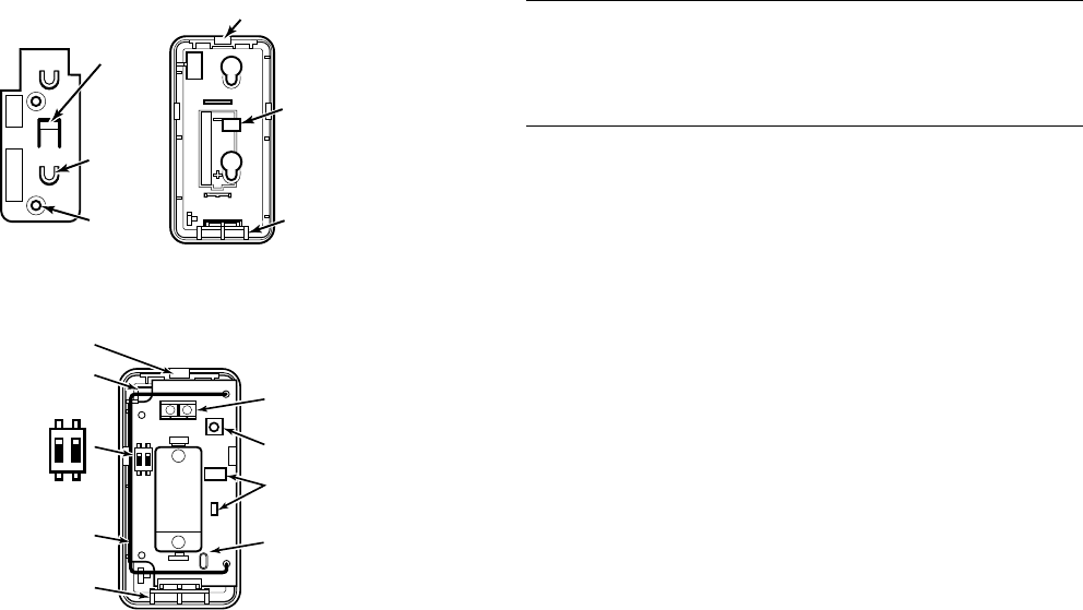
1. Remove the transmitter's top cover by inserting the flat
blade of a small screwdriver into the pry-off slot at one
end of the unit (see Figure 1 for location), and slightly
twisting the blade until the cover disengages.
2. Install a 3-volt lithium battery as shown in Figure 1.
TAMPER SUPERVISION
The 5821 tamper supervision feature (Loop 4) causes a
trouble signal to be sent to the control if the unit’s cover is
removed from the base or if an external probe is used and
the wire is cut (open) or the probe is shorted. The tamper
switch is also used to program the unit’s serial number and
loop assignments to the control panel.
SETTING THE OPERATING MODE
Table 1 provides a list of the various operating modes of the
5821 with the respective Loop and DIP Switch settings for
each. Note that Cold Temp Sensing can be used in
combination with any of the other operating modes. To use
the transmitter to monitor two different conditions, you
must program each loop used on the 5821 as its own zone,
and you must set the DIP Switches as shown for the
combination functions in Table 1.
PROGRAMMING THE UNIT
Once you have selected an operating mode and have set the
DIP Switches accordingly, you must enroll the transmitter
in the control panel. When programming the transmitter in
the control panel, note that you must program a separate
zone for each loop you are using on the transmitter. To
program:
1. Enter the control’s Zone Programming mode.
2. Enter the zone number to be programmed.
3. Enter the applicable zone type when prompted (zone
types such as 24-Hr. Aux, Waterflow, etc. should be
used) depending on the function of the zone and the
control panel being used (see the control panel’s
instructions for available zone types and definitions).
4. When prompted, enter Input Type 03 (3 on some
controls) – Supervised RF Transmitter.
5. When prompted for the serial number, transmit from
the detector by pressing the tamper switch.
6. When the serial number is displayed, transmit from the
detector again by pressing the tamper switch.
The current loop number (4) will begin to flash.
7. Manually change the loop number to the desired loop
number for the zone (according to the application—see
Table 1).
8. When programming for this zone is complete, program
other zones for the transmitter as necessary (each loop
requires its own zone.
9. Exit Programming mode when programming is
complete, and test the detector. Refer to the Testing
section.
FCC / IC STATEMENT IS ON PAGE 4
(OR USE BOOK MARK )
2
MOUNTING THE DETECTOR
You can mount the 5821 on a wall or ceiling within the
protection area. The following notes apply:
• The 5821 may be installed in any direction.
• When used in-conjunction with the ADEMCO 470PB
flood sensor probe, use no more than 48 inches of wire
from the 5821 to the flood sensor and connect the
termination resistor across the probes terminals.
• When used in-conjunction with ADEMCO T280R
temperature probe, use the shortest wire possible (less
than 96 inches) to improve the signal integrity.
• Although the unit can be mounted directly to a surface,
we recommend that the mounting plate be used for ease
of removal for servicing if necessary. Avoid mounting
the detector near heat generating devices (e.g. ovens,
heat vents, furnaces, boilers) or to a metal cabinet or
surface.
Wireless Transmission Path Test
A good RF transmission path must be established from the
proposed mounting location before permanently installing
the detector. To determine that there is good signal
reception from the proposed location, perform the test
procedure described in TESTING THE DETECTOR section.
Once a good RF transmission path is confirmed, mount the
detector as follows, referring to Figure 1.
5821-001-V0
LOCKING
TA B
RELEASE
WINDOW
COVER PRY-OFF SLOT
MOUNTING
PLATE
HOLES (2)
OBSERVE POLARITY
LOCKING
TAB
WIRES
MOUNTING PLATE CASE
COVER
RETAINING
HOOKS
(3)
POST (2)
5821-002-V1
LOOP
TERMINALS
BATTERY
CR123A
COVER
RETAINING
HOOKS (3)
ANNTENNA
DIP SWITCH
+
+
COVER
PRY-OFF
SLOT
WIRE ENTRY
HOLE
TAMPER
SWITCH
IC
CRYSTAL
+
_
21
ON
21
ON
Figure 1
To mount the detector, proceed as follows:
1. Remove the transmitter's top cover by inserting the flat
blade of a small screwdriver into the 'pry-off' slot at one
end of the unit (see Fig. 1 for location), and slightly
twisting the blade until the cover disengages.
IMPORTANT: DO NOT remove the circuit board from the
back case plastic.
2. Remove the battery.
3. Disengage the attached mounting plate from the case
by inserting the blade of a small screwdriver into the
locking tab release window (see Figure 1) and pressing
it against the locking tab, while sliding the mounting
plate upward along the case back until free.
4. Install the mounting plate, with its two case- holding
posts pointing up (in this example), in the location
selected. Use the flat-head screws supplied.
5. For surface wiring entry, two thin "breakout" areas are
provided in the case wall (see Figure 1).
6. Attach the case back to the mounting plate by sliding
the keyhole slots in the case back down onto the
mounting plate's case holding posts. The locking tab
will click as the case back locks in place.
External Probe Wiring Connections (If used)
7. With the battery still not inserted, connect the wires to
the unit's sensor terminals (see Figure 1).
8. Install the battery.
IMPORTANT:
This detector should be used for property protection.
Reliance should not be placed on this detector for life safety.
When life safety is involved, smoke detectors MUST also be
used. The flood probe must not be painted.
TESTING THE DETECTOR
The test procedure should be performed to determine a good
RF transmission path and again after installation is
completed. To test,
1. Activate the control panel’s test mode.
2. Activate the detector by removing and replacing
the cover. The system’s keypads should beep and
each zone the 5821 is programmed for will be
displayed.
3. Exit the control’s test mode (User Code + OFF).
MAINTAINING PROPER OPERATION
To maintain the detector in proper working condition, it is
important that you observe the following:
Replace the battery when the system indicates that the
5821 reported a low battery condition.
Units should never be relocated without the advice or
assistance of the alarm service company.

3
Table 1: 5821 Operating Mode Choices
✝ When the 5821 is used with either external probe, an open-circuit or a short-circuit of the probe’s wiring results in an alarm on
that loop, and a trouble condition on all other programmed loops.
✝✝ Use a maximum wire length of 48 inches between the 5821 and the 470PB probe.
Operating Mode
Dip
Switch
Setting Loop Faults when… Restores when…
External
Probe ✝
Cold Temp Sensing SW1=OFF
SW2=OFF
1 temperature drops below
45°F (7°C) for >10 minutes.
temperature rises 48°F (9°C)
for >4 minutes.
No external
probe
Hot Temp Sensing SW1=OFF
SW2=OFF
2 temperature rises above
95°F (35°C) for >10 minutes.
temperature drops below 92°F
(33°C) for > 4 minutes.
No external
probe
Warm Temp
Sensing
SW1=ON
SW2=OFF 2 temperature rises above
75°F (24°C) for >10 minutes.
temperature drops below 72°F
(22°C) for > 4 minutes.
No external
probe
Freezer Temp
Monitoring
SW1=OFF
SW2=ON 2
temperature rises above
10°F
(-12°C) for >30 minutes.
temperature drops below 7°F
(-14°C) for > 4 minutes.
Use T280R
external probe
Refrig. Temp
Monitoring
SW1=ON
SW2=ON 2 temperature rises above
42°F (6°C) for >30 minutes.
temperature drops below 39°F
(4°C) for > 4 minutes.
Use T280R
external probe
Flood Sensing SW1=OFF
SW2=ON 3
external probe tips are in
contact with water for >3
minutes.
probe tips have not been in
contact with water for > 3
minutes.
Use 470PB ext.
probe shunted by
2.2MΩ resistor ✝✝
Cold Temp Sensing
&
SW1=ON
1=Cold
temperature drops below
45°F (7°C) for >10 minutes.
temperature rises 48°F (9°C)
for >4 minutes.
Warm Temp
Sensing
SW2=OFF 2=Warm temperature rises above
75°F (24°C) for >10 minutes.
temperature drops below 72°F
(22°C) for > 4 minutes.
No external probe
Cold Temp Sensing
&
SW1=OFF 1=Cold temperature drops below
45°F (7°C) for >10 minutes.
temperature rises 48°F (9°C)
for >4 minutes.
Hot Temp Sensing SW2=OFF 2=Hot temperature rises above
95°F (35°C) for >10 minutes.
temperature drops below 92°F
(33°C) for > 4 minutes.
No external probe
Cold Temp Sensing
&
SW1=ON
1=Cold temperature drops below
45°F (7°C) for >10 minutes.
temperature rises 48°F (9°C)
for >4 minutes.
Refrig. Temp
Monitoring
SW2=ON 2=Refrig temperature rises above
42°F (6°C) for >30 minutes.
temperature drops below 39°F
(4°C) for > 4 minutes.
Use T280R
external probe
Cold Temp Sensing
&
SW1=OFF 1=Cold
temperature drops below
45°F (7°C) for >10 minutes.
temperature rises 48°F (9°C)
for >4 minutes.
Freezer Temp
Monitoring
SW2=ON 2=Freezer temperature rises above
10°F (-12°C) for >30
minutes.
temperature drops below 7°F
(-14°C) for > 4 minutes.
Use T280R
external probe
Cold Temp Sensing
&
SW1=OFF 1=Cold
temperature drops below
45°F (7°C) for >10 minutes.
temperature rises 48°F (9°C)
for >4 minutes.
Flood Sensing SW2=ON 3=Flood external probe tips are in
contact with water for >3
minutes.
probe tips have not been in
contact with water for > 3
minutes.
Use 470PB
ext. probe
shunted by
2.2MΩ resistor ✝✝

ÊK9947V3ÈŠ
K9947V3 5/08 Rev. A
SPECIFICATIONS
Power: 3V lithium battery
(Duracell DL123A, Panasonic CR123A)
CAUTION: Risk of fire, explosion, and burns. Do not
recharge, disassemble, heat above 212°F
(100°C) or incinerate. Dispose of used batteries
promptly. Keep away from children.
Operating Temperature: 14°F (-10°C) to 104°F
(+40°C)
Operating Voltage: 3.2VDC
Dimensions: 3.1” length, 1.6”wide, 1.0”
depth
Sensor Parameters:
Cold Temperature
(Freeze) Detector 45°F (7°C)
Warm Temperature
Detector 75°F (24°C)
Hot Temperature
Detector 95°F (35°C)
Refrigerator Failure
Detector 42°F (6°C)
Freezer Failure
Detector 10°F (-12°C)
Hysteresis ✝✝✝ 3°F (-16°C)
Flood Sensor ¼ inch of water covering
the probe
Response Time
Tolerance ✝✝✝✝ +50%, -20%
Temperature Measurement
Accuracy (internal temp. sensor
or external temp. probe) ±3°F (-16°C)
✝✝✝ Hysteresis is the temperature difference between “fault” and
“restore” points.
✝✝✝✝ The Response Time Tolerance is the time duration necessary
for the device to respond to a “fault” or “restore” condition.
This time does not take into account the time necessary for
the probe and circuitry to equalize to the ambient
temperature. This feature prevents false alarms due to open
doors and other transitory conditions.
TO THE INSTALLER
Regular maintenance and inspection (at least annually) by the
installer and frequent testing by the user are vital to continuous
satisfactory operation of any alarm system.
The installer should assume the responsibility of developing and
offering a regular maintenance program to the user as well as
acquainting the user with the proper operation and limitations of
the alarm system and its components parts. Recommendations
must be included for a specific program of frequent testing (at least
weekly) to ensure the system’s proper operation at all times.
FCC / IC STATEMENT
This device complies with Part 15 of the FCC rules and RSS210 of
Industry Canada. Operation is subject to the following two
conditions: (1) This device may not cause harmful interference, and
(2) this device must accept any interference received, including
interference that may cause undesired operation.
Unauthorized changes or modifications could void the user's
authority to operate the equipment.
REFER TO THE INSTALLATION AND SETUP GUIDE FOR THE
CONTROL PANEL WITH WHICH THIS DEVICE IS USED FOR
WARRANTY INFORMATION AND LIMITATIONS OF THE
ENTIRE ALARM SYSTEM.
2 Corporate Center Drive, Suite 100
P.O. Box 9040, Melville, NY 11747
Copyright 2008 Honeywell International Inc.
www.honeywell.com/security