Ademco 8DL5842 Security Transceiver User Manual K9674
Honeywell International Inc. Security Transceiver K9674
Ademco >
II with FCC Part 15 Statments
DRAFT – 24 February 2004
K9674ax 2/04 Rev. A
$'(0&2
:LUHOHVV'LDOHU
Installation and Setup Guide
GENERAL INFORMATION
The 5842 Wireless Dialer is a combination Central Station
dialer and RF transceiver. It receives and acknowledges RF
messages from the control’s transceiver. In response, it
sends reports to the central station via the dialer. The 5842
also sends acknowledgements, supervisory and tamper RF
transmissions to the control.
DIALER FEATURES
• ADEMCO Contact ID® central station reporting format.
• Reports low battery conditions to control panel.
• Front cover tamper switch.
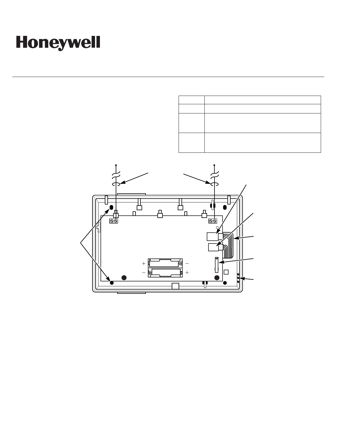
The LEDs and their functions are described below:
LED Function
Green Lights continuously and flickers during RF activity.
Yellow Flashes once each time the 5842 sends an
acknowledge message to the control. Stays on while
the dialer is using the telephone line.
Red Lights to indicate no setup information has been
received, or setup information is incomplete. Once
setup information is received the LED will go off.
REDYELGRN
MOUNTING
HOLES
(4)
ANTENNAS
(INSERT IN
RIGHT-HAND
TERMINALS)
BREAKOUT
WIRING
OPENING
TAMPER
SWITCH
RJ31X
TELEPHONE
JACK
WIRING
OPENING
5842-001-V0
TELEPHONE IN
TELEPHONE OUT
RJ11
TELEPHONE
JACK
BATTERY
BATTERY
Figure 1 - 5842 Wireless Dialer (cover removed)
OPERATION
The 5842 dialer is triggered by an RF message that contains a command, (i.e. a dialer report message or a line seize and clear
command). It processes the command and remains active for a short time after it has received and acknowledged the last RF
message from the control panel. The 5842 then reverts to Low current standby mode. The Wireless Dialer is normally in a low
current standby mode, which maximizes battery life. At specific intervals the unit’s RF receiver is switched on, and listens for a
“Time Sync” message from the control panel. If the “Time Sync” message is not received within a specified time the 5842 switches
to an active receiving state. If the 5842 still does not receive a message it transmits a time sync fault to the control panel. Normal
operation resumes after the control panel logs the event and transmits a “Time Sync Fault Restore” message. Failure to receive a
kiss-off signal from the central station is reported to the control panel. Dialer reports are sent to the central station using
ADEMCO Contact ID® format only.
PROGRAMMING AND INSTALLING THE 5842 WIRELESS DIALER
Refer to the following procedure and the Installation and Setup Guide for the Control Panel being installed to program and
install the 5842 Wireless Dialer:
-2-
If the 5842 batteries are removed refer to REPLACING THE BATTERIES section before reinstalling/replacing the cells. Use only
1.5-volt alkaline batteries. Observe the polarity when installing batteries.
STEP DESCRIPTION
1. Remove the cover from the 5842 Wireless Dialer.
Note: The 5842 is configured to accept programming data any time the cover is removed from the unit. The unit performs this function whether or not it has
been previously programmed.
2. Place the control in the Programming Mode and enable operation with the 5842 Wireless Dialer. Refer to the procedure in the Installation
and Setup Guide for the Control Panel that is being installed.
3. Install each antenna in the respective right-hand terminal of the two terminal blocks at the upper edge of the 5842’s circuit board, and tighten
the screws to secure them. (Refer to Figure 1.)
4. Install two 1.5V AA batteries in the 5842. The 5842 will activate its receiver and begin listening for an RF broadcast from the control panel.
The panel’s Green, Yellow and Red LEDs will come on for one- (1) second after the unit is powered-up.
Notes: (1) Do not mount the 5842 or install the cover at this time.
(2) To conserve battery life, the 5842’s listen mode has a five (5) minute time-out. If the 5842 times out, install and remove the cover to restart the
listen mode.
5. Exit the control panel’s programming mode by entering ✻99.
6. The control panel will transmit the setup information and the 5842’s Green and Yellow LEDs will flash briefly.
7. The control panel will indicate receipt of the RF acknowledgement from the 5842 by beeping three times and the 5842’s red LED will go out.
8. Install the cover on the 5842.
9. Place the control panel in Go/No Go Test Mode.
10. After selecting a mounting location for the 5842 remove and replace the cover to activate the tamper and ensure the control has received the
transmission.
11. Exit the controls Go/No Go Test Mode (Refer to the Installation Instructions for the Control Panel being installed) and cause the control to
send several dialer reports via the 5842. Ensure that the central station receives each report.
12. For concealed wiring, route wires through the rectangular opening at the rear of the base before mounting. For surface wiring entry, a thin
breakaway area is provided along the base's right edge.
13. Mount the case back to a wall or to and electrical box using the 25mm-long self-tapping screws that are supplied (mollies for drywall are not
supplied).
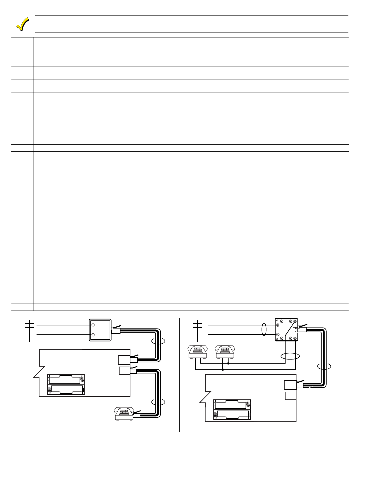
14. Make Phone Line Connections - For local or full line seizure proceed to the appropriate steps below and refer to figure 2.
Local Seizure: Only the telephone equipment connected to the 5842 Wireless Dialer’s RJ11 jack will be disconnected to prevent
interference while the 5842 is using the phone line. This may or may not include ALL the telephone equipment on the premises.
a. Connect the incoming phone line to the 5842’s internal RJ31 jack.
b. Connect the handset phone lines to either 5842’s internal RJ11 jack.
Full Line Seizure: Requires the installation of an RJ31X jack at the network demarcation (before any other premises connections). It
ensures that the ALL premises telephone equipment is disconnected and will not interfere with the 5842 while it is using the phone line. In
the event of a problem with the 5842 it will also ensure uninterrupted service to all premises telephone equipment when the cable to the
5842 has been disconnected from the RJ31X jack.
a. Cut the incoming RING and TIP phone lines (typically red and green, respectively) and connect them to RJ31X terminals 4 (red) and 5
(green).
b. Connect the premises end of the cut RING and TIP wires to RJ31X terminals 1 (grey) and 8 (brown) respectively.
c. Plug one end of the Direct Connect Cord to the wireless dialer’s internal RJ31 jack.
d. Plug the other end of the Direct Connect Cord into the RJ31X jack.
15. Install the cover on the 5842 and secure it with the provided screw.
5842-002-V1
TELEPHONE IN
TELEPHONE OUT
INCOMING
PHONE LINE
INCOMING
PHONE LINE
DIRECT CONNECT
TELCO
TERMINATION
BLOCK
RJ31X
RJ11
FULL LINE SEIZURE CONNECTIONS
LOCAL LINE SEIZURE CONNECTIONS
DIRECT
CONNECT
DIRECT CONNECT
RJ31X
GRAY
RED
GREEN BROWN
4
1
23
5
678
TO PREMISES PHONES
RING
TIP
RING
TIP
TO CONTROL PANEL
(FOR BACKUP
REPORTING)
5842
TELEPHONE IN
TELEPHONE OUT
RJ31X
RJ11
5842
Figure 2 - 5842 Telephone Connections

-3-
REPLACING THE BATTERIES
STEP DESCRIPTION
1. Remove the cover from the 5842 Wireless Dialer.
2. Remove two 1.5-volt AA batteries.
3. Place the control panel into programming mode. Refer to the procedure in the Installation and Setup Guide for the Control Panel.
Note: Wait at least 30 seconds before reinstalling/replacing the cells.
4. Install two 1.5-volt AA alkaline batteries.
Note: Observe the polarity when installing batteries.
5. Exit the control panel’s programming mode by entering ✻99.
6. Install the cover on the 5842.
SPECIFICATIONS
Physical: 5.5" H x 8" W x 2.5"D
Antenna: Dual Antennas for spatial diversity.
Range: 200 Ft (60.9 m) nominal
Frequency: 345 MHz
Telephone Interface: One (1), RJ-31 Jack labeled “IN”
and One (1), RJ-11 Jack labeled
“OUT”
Battery: Two (2) 1.5-volt Alkaline cells
FOR DETAILS ON THE LIMITATIONS OF THE ENTIRE ALARM SYSTEM, REFER TO THE INSTALLATION INSTRUCTIONS FOR THE CONTROL PANEL THAT IS
BEING INSTALLED IN CONJUCTION WITH THIS DEVICE.
Limited Warranty
Honeywell International Inc., 165 Eileen Way, Syosset, New York 11791, warrants its products to be in conformance with its own plans and
specifications and to be free from defects in materials and workmanship under normal use and service for 24 months from the date stamp control on
the product or, for products not having an Ademco date stamp, for 12 months from date of original purchase unless the installation instructions or
catalog sets forth a shorter period, in which case the shorter period shall apply. Seller's obligation shall be limited to repairing or replacing, at its
option, free of charge for materials or labor, any product, which is proved not in compliance with Seller's specifications or proves defective in materials
or workmanship under normal use and service. Seller shall have no obligation under this Limited Warranty or otherwise if the product is altered or
improperly repaired or serviced by anyone other than Honeywell factory service. For warranty service, return product transportation prepaid, to
Honeywell Factory Service, 165 Eileen Way, Syosset, New York 11791.
THERE ARE NO WARRANTIES, EXPRESS OR IMPLIED, OF MERCHANTABILITY, OR FITNESS FOR A PARTICULAR PURPOSE OR
OTHERWISE, WHICH EXTEND BEYOND THE DESCRIPTION ON THE FACE HEREOF. IN NO CASE SHALL SELLER BE LIABLE TO ANYONE
FOR ANY CONSEQUENTIAL OR INCIDENTAL DAMAGES FOR BREACH OF THIS OR ANY OTHER WARRANTY, EXPRESS OR IMPLIED, OR
UPON ANY OTHER BASIS OF LIABILITY WHATSOEVER, EVEN IF THE LOSS OR DAMAGE IS CAUSED BY THE SELLER'S OWN NEGLIGENCE
OR FAULT.
Seller does not represent that the products it sells may not be compromised or circumvented; that the products will prevent any personal injury or
property loss by burglary, robbery, fire or otherwise; or that the products will in all cases provide adequate warning or protection. Customer
understands that a properly installed and maintained alarm may only reduce the risk of a burglary, robbery, fire or other events occurring without
providing an alarm, but it is not insurance or a guarantee that such will not occur or that there will be no personal injury or property loss as a result.
CONSEQUENTLY, SELLER SHALL HAVE NO LIABILITY FOR ANY PERSONAL INJURY, PROPERTY DAMAGE OR OTHER LOSS BASED ON A
CLAIM THE PRODUCT FAILED TO GIVE WARNING. HOWEVER, IF SELLER IS HELD LIABLE, WHETHER DIRECTLY OR INDIRECTLY, FOR
ANY LOSS OR DAMAGE ARISING UNDER THIS LIMITED WARRANTY OR OTHERWISE, REGARDLESS OF CAUSE OR ORIGIN, SELLER'S
MAXIMUM LIABILITY SHALL NOT IN ANY CASE EXCEED THE PURCHASE PRICE OF THE PRODUCT, WHICH SHALL BE THE COMPLETE
AND EXCLUSIVE REMEDY AGAINST SELLER. This warranty replaces any previous warranties and is the only warranty made by Seller on this
product. No increase or alteration, written or verbal, of the obligations of this Limited Warranty is authorized.
FCC ID: CFS8DL5842
CANADA: 1748542
FCC STATEMENT
Federal Communications Commission (FCC) Part 15
This device complies with part 15 of the FCC rules. Operation is subject to the following two conditions: (1) This device may not cause harmful interference, and (2) this
device must accept any interference received, including interference that may cause undesired operation.
Industry Canada
This Class B digital apparatus complies with Canadian ICES-003.
Cet Appareil numérique de la classe B est conforme à la norme NMB-003 du Canada.
Federal Communications Commission (FCC) Part 15 Statement
This equipment has been tested to FCC requirements and has been found acceptable for use. The FCC requires the following statement for your information:
This equipment generates and uses radio frequency energy and if not installed and used properly, that is, in strict accordance with the manufacturer's instructions, may
cause interference to radio and television reception. It has been type tested and found to comply with the limits for a Class B computing device in accordance with the
specifications in Part 15 of FCC Rules, which are designed to provide reasonable protection against such interference in a residential installation. However, there is no
guarantee that interference will not occur in a particular installation. If this equipment does cause interference to radio or television reception, which can be determined by
turning the equipment off and on, the user is encouraged to try to correct the interference by one or more of the following measures:
• If using an indoor antenna, have a quality outdoor antenna installed.
• Reorient the receiving antenna until interference is reduced or eliminated.
• Move the radio or television receiver away from the receiver/control.
• Move the antenna leads away from any wire runs to the receiver/control.
• Plug the receiver/control into a different outlet so that it and the radio or television receiver are on different branch circuits.
If necessary, the user should consult the dealer or an experienced radio/television technician for additional suggestions. The user or installer may find the following booklet
prepared by the Federal Communications Commission helpful: "Interference Handbook." This booklet is available from the U.S. Government Printing Office, Washington,
DC 20402. The user shall not make any changes or modifications to the equipment unless authorized by the Installation Instructions or User's Manual. Unauthorized
changes or modifications could void the user's authority to operate the equipment.
ACTA US: AC3AL00BK5842
TELEPHONE/MODEM INTERFACE
Federal Communications Commission (FCC) Part 68
This equipment complies with Part 68 of the FCC rules and the requirements adopted by the ACTA. On the front cover of this equipment is a label that contains among other
information, a product identifier in the format US:AAAEQ##TXXX. You must provide this information to the telephone company when requested.
A plug and jack used to connect this equipment to the premises wiring and telephone network must comply with the applicable FCC Part 68 rules and requirements adopted
by the ACTA. A compliant telephone cord and modular plug is provided with this product. It is designed to be connected to a compatible RJ31X modular jack that is also
compliant. (Refer to the installation instructions for details.)
Ringer Equivalence Number (REN) Notice:
The REN is used to determine the number of devices that may be connected to a telephone line. Excessive REN’s on a telephone line may result in the devices not ringing in
response to an incoming call. In most but not all areas, the sum of the REN’s should not exceed five (5). To be certain of the number of devices that may be connected to a
line, as determined by the total REN’s, contact the local telephone company. The REN for this product is part of the product identifier that has the format
US:AAAEQ##TXXXX. The digits represented by ## are the REN without a decimal point (e.g., 03 is a REN of 0.3).
If this equipment causes harm to the telephone network, the telephone company will notify you in advance that temporary discontinuance of service may be required. If
advance notice not practical, the telephone company will notify the customer as soon as possible. You will be advised of your right to file a complaint with the FCC if you
believe it is necessary.
Changes made by the Telephone Company, to its facilities, equipment, operations or procedures could affect the operation of this equipment. In the event that this should
occur the telephone company will provide advance notice in order for you to make necessary modifications to maintain uninterrupted service.
If trouble is experienced with this equipment
,
for repair or warranty information, refer to the Limited Warranty that is provided. If the equipment is causing harm to the
telephone network, the telephone company may request that it be disconnected until the problem has been resolved.
Connection to party line service is subject to state tariffs. Contact the state public utility commission, public service commission or corporation commission for information.
WHEN PROGRAMMING EMERGENCY NUMBERS AND (OR) MAKING TEST CALLS TO EMERGENCY NUMBERS:
1) Remain on the line and briefly explain to the dispatcher the reason for the call.
2) Perform such activities in the off-peak yours, such as early morning or late evenings.
ALLOWING THIS EQUIPMENT TO BE OPERATED IN SUCH A MANNER AS TO NOT PROVIDE FOR PROPER ANSWER SUPERVISION IS A VIOLATION OF PART 68
OF THE FCC’S RULES.
Caution – To insure proper operation, this equipment must
be installed according to the enclosed installation
instructions. To verify that the equipment is operating
properly and can successfully report an alarm, this
equipment must be tested immediately after installation,
and periodically thereafter, according to the enclosed test
instructions.
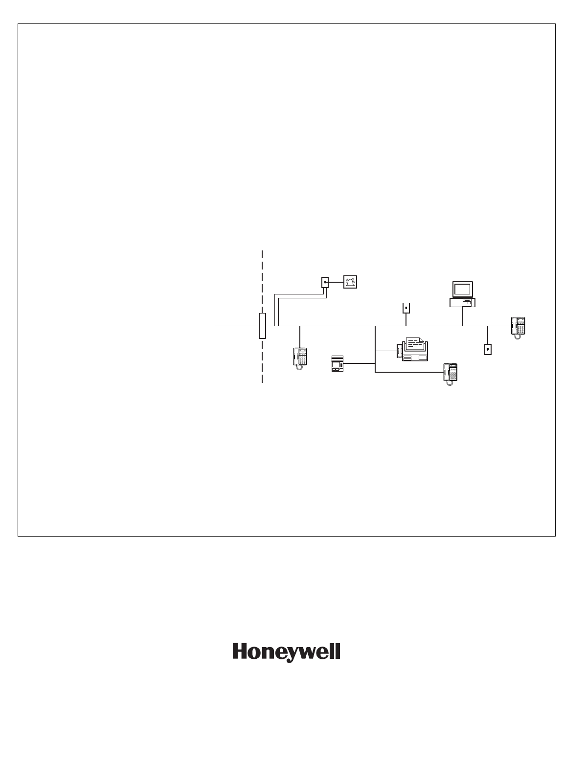
In order for ‘alarm dialing equipment’ to be able to seize the
phone line to report an alarm or other event when other
customer equipment (telephone, answering system,
computer modem, etc.) connected to the same line is in
use, the ‘alarm dialing equipment’ must be connected to a
properly installed RJ31X jack that is electrically in series
with and ahead of all other equipment attached to the same
telephone line. Proper installation is depicted in the figure
below. If you have any questions concerning these
instructions, you should consult your telephone company or
a qualified installer about installing the RJ31X jack and
alarm dialing equipment for you.
NETWORK
DEMARCATION
POINT
NETWORK
SERVICE
PROVIDER'S
FACILITIES
TELEPHONE
LINE
RJ31X
JACK
TELEPHONE
ANSWERING
SYSTEM
ALARM DIALING
EQUIPMENT
UNUSED
RJ11 JACK
UNUSED
RJ11 JACK
COMPUTER
CUSTOMER PREMISES EQUIPTMENT AND WIRING
TELEPHONE
TELEPHONE
fcc_diag
FAX MACHINE
Industry Canada
NOTICE: The Industry Canada Label identifies certified equipment. This certification means that the equipment meets telecommunications network protective, operational
and safety requirements as prescribed in the appropriate Terminal Equipment Technical Requirements document(s). The Department does not guarantee the equipment will
operate to the user’s satisfaction.
Before installing this equipment, users should ensure that it is permissible to be connected to the facilities of the local telecommunications company. The equipment must also
be installed using an acceptable method of connection. The customer should be aware that compliance with the above conditions may not prevent degradation of service in
some situations.
Repairs to certified equipment should be coordinated by a representative designated by the supplier. Any repairs or alterations made by the user to this equipment, or
equipment malfunctions, may give the telecommunications company to request the user to disconnect the equipment.
Users should ensure for their own protection that the electrical ground connections of the power utility, telephone lines and internal metallic water pipe system, if present, are
connected together, This precaution may be particularly important in rural areas.
Caution: Users should not attempt to make such connections themselves but should contact appropriate electric inspection authority, or electrician, as appropriate.
Ringer Equivalence Number Notice:
The Ringer Equivalence Number (REN) assigned to each terminal device provides an indication of the maximum number of terminals allowed to be connected to a
telephone interface. The termination on an interface may consist of any combination of devices subject only to the requirement that the sum of the Ringer Equivalence
Numbers of all the devices does not exceed 5.
i.-l
K9674ax 2/04 Rev. A
165 Eileen Way, Syosset, New York 11791
Copyright 2004 Honeywell International Inc.
www.security.honeywell.com