Ademco 8DL5870API Indoor Asset Protection Device User Manual K14379 ii
Honeywell International Inc. Indoor Asset Protection Device K14379 ii
Ademco >
Contents
- 1. Users Manual
- 2. Manual
Users Manual
K14379 4/07 Rev. A
ADEMCO 5
ADEMCO 5ADEMCO 5
ADEMCO 5870API
870API870API
870API
Wireless Indoor Asset Protection Device
Wireless Indoor Asset Protection DeviceWireless Indoor Asset Protection Device
Wireless Indoor Asset Protection Device
INSTALLATION AND SETUP GUIDE
GENERAL INFORMATION
The ADEMCO 5870API is a wireless, supervised asset
protection device that uses patented Micro-Electro-
Mechanical System (MEMS) technology, which references
the Earth’s gravitational field. When affixed to a
protected high-value asset the device will trigger an
alarm if an attempt is made to move or disturb the asset.
ADEMCO VISTA P-series control panels (VISTA-10P,
15P and 20P) provide configurable zone types that allow
the installer to customize a zone for asset protection (i.e.,
24 hour supervisory alarm, trouble by day/alarm by night,
etc.) Refer to the control panel installation instruction for
full details.
The 5870API is intended for use in systems that support
5800 series devices. Each transmitter has its own unique
serial number, assigned during manufacture, which must
be “enrolled” in the control panel before the device can be
used with the system. Refer to the control panel's
Installation and Setup Guide for programming details.
One 5870API is required for each asset that will be
protected.
Typical Protected Assets
The 5870API can be used for many residential and
commercial applications such as:
Residential Commercial
• Electronic equipment • Office Equipment
• Jewelry boxes • Museum Art
• Paintings and Art • Laboratory Equipment
• Entertainment devices
• House or Gun Safe
• Antiques and Collectables
The 5870API sensor is for use on objects that do not
move frequently or vibrate. Mounting the sensor near
sources of vibration may cause false alarm
conditions to occur.
Operating Modes
The 5870API is equipped with three programming
options. A three minute inhibit prevents excessive RF
transmissions and preserves battery life by transmitting
alarm signals three minutes apart.
Short Travel Time Detection (Loop 1) – This is a
high-security, minimum movement mode in which the
sensor detects the movement of the device over a short
time period and sends an alarm signal after one second of
continuous movement. When the motion has stopped for
period of three seconds, a restore signal is sent.
Long Travel Time Detection (Loop 2) – The sensor
detects the movement of the device over a longer time
period in this mode and sends an alarm signal after five
seconds of continuous movement. When the motion has
stopped for period of three seconds, a restore signal is
sent.
Open/Close Sensor (Loop 3) – This mode is intended
for boxes with lids that can be opened (e.g.; jewelry boxes).
The sensor detects tilt with respect to the horizon. If the
unit is tilted more than 30° of tilt with respect to the
Earth the sensor will send an alarm signal. If the unit is
tilted back to less than 15° a restore signal will be sent.
The 5870API is not watertight, and therefore should
not be used in damp locations. Do not use the device
in applications that may be exposed to moisture. The
device may be used in garages, sheds, etc., as long
as it is not at risk from rain, snow, humidity or
condensation. The device should not be installed in
locations where temperatures may drop below 14° F.
OPERATION
Upon initial battery power up, the unit will transmit
every time it is faulted or restored, which enables you to
program and test the device. To conserve battery life the
sensor’s normal operating mode has a three-minute
lockout on Loops 1, 2 and 3. Once a restore has been sent
on any loop, further transmissions on that loop are
inhibited for three minutes. Other loops are not affected.
The sensor automatically switches from installer test
mode to normal mode after the first supervisory
transmission is sent. This will occur approximately 72
minutes after the last fault/restore message has been
sent.
To return to the installer test mode remove and reinstall
the battery.
TAMPER SUPERVISION
The 5870API tamper supervision feature (Loop 4) causes
a trouble signal to be sent to the control if the sensor is
removed from the asset being protected or if the unit’s
cover is removed from the base. The tamper switch is
also used to program the unit’s serial number and loop
assignments to the control panel.
SETTING THE OPERATING MODE
You must enroll the 5870API serial number in the control
panel during zone programming. The control panel's
Installation and Setup Guide provides detailed program-
ming procedures. Table 1 provides a list of the various
operating modes of the 5870API with the respective Loop
numbers for each. Before programming, perform the
following:
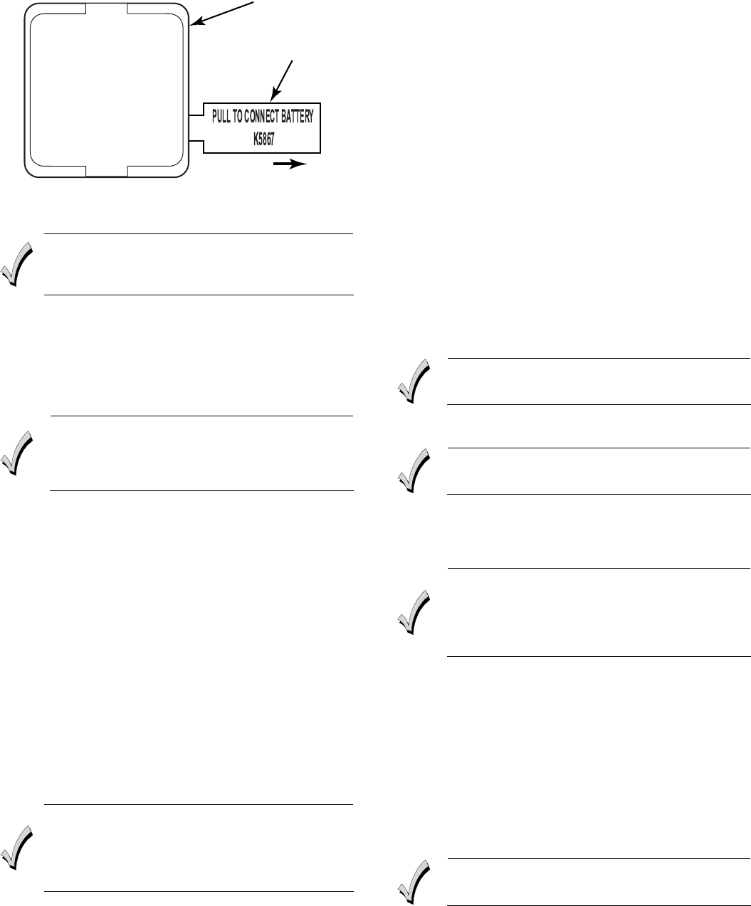
1. To cause the transmitter to transmit, remove the
“PULL TO CONNECT BATTERY” tab (see Figure 1).
(For additional transmissions, move or rotate the
sensor.)
2. When the battery is connected the sensor powers up
in the installer test mode. In this mode the sensor
will transmit fault and restore messages on all loops
when it detects the corresponding motion (or lack
thereof).
PLEASE GO TO THE BOTTOM OF PAGE 4
FOR THE FCC AND IC STATEMENTS
- 2 -
5870API-002-V0
PULL
TAB
SENSOR
Figure 1 - 5870API Battery Tab
PROGRAMMING THE UNIT
If you are enrolling this device on a LYNXR-Series
control panel refer to the *56 Enhanced Zone
Programming Mode section in the LYNXR Installation
Guide for programming information.
Once you have selected an operating mode you must
enroll the transmitter in the control panel. When
programming the transmitter in the control panel, note
that you must program a separate zone for each loop you
are using on the transmitter. To program:
1. Enter the control’s Zone Programming mode.
2. Enter the zone number to be programmed.
If the asset being protected should not be moved (i.e.,
a painting) it can be programmed as a 24 hour zone
type. If the asset will occasionally be moved, when the
system is disarmed, it can be programmed as a
perimeter zone type .
3. When prompted, enter zone type.
4. When prompted, enter Input Type 03 (3 on some
controls) – Supervised RF Transmitter.
5. When prompted for the serial number, transmit from
the detector by pressing the tamper switch.
6. When the serial number is displayed, transmit from
the detector again by pressing the tamper switch.
The current loop number (4) will begin to flash.
7. Manually change the loop number to the desired loop
number for the zone (according to the application—
see Table 1).
8. If you are enrolling this device on a Vista-series
control, press the * key to skip the confirmation
screen.
9. Exit Programming mode when programming is
complete, and test the detector. Refer to the Testing
section.
MOUNTING
1. Replace the adhesive when relocating the device.
2. Ideal application temperature range of the tape is
70-100°F (21-38°C). Initial tape application to
surfaces below the suggested minimum
temperature is not recommended because the
adhesive becomes too firm to adhere readily.
The 5870API can be permanently or temporarily mounted
directly to the asset to be protected via 3M VHB double-
sided tape or removable adhesive double-sided tape. Two
types of tape are provided with the device and the
selections should be based on the end use environment
and conditions. Once cured the black tape (with red
release liner) has a stronger bond, except in low
temperature applications where the gray tape should be
used.
1. Determine the optimum mounting location taking care
to avoid damp locations. To maximize the
transmitter’s range avoid mounting the device to
metal objects, if possible.
2. Temporarily mount the device to the asset to be
protected using masking tape or any suitable method.
3. Before the transmitter is permanently mounted,
conduct Go/No Go tests (refer to the Control Panel’s
instructions) to verify adequate signal strength from
the mounting location.
4. Always verify range by holding the sensor in the
approximate mounting location and moving the asset.
The panel (in test mode) should respond to the
transmissions. If not, find a more suitable mounting
location.
5. If your application (“permanent”) requires the black
tape, remove the gray tape. Clean any fingerprints
and adhesive residue and install the black tape on the
sensor.
Take care to align the hole in the tape with the
device’s tamper switch plunger.
6. Clean the area, where the sensor will be mounted,
with a mixture of water and isopropyl alcohol.
To obtain proper performance with all 3M VHB tapes,
it is important to ensure that the surfaces are dry and
free of condensed moisture.
7. Once the surface has been cleaned, remove the tape
backing paper and firmly press the sensor in the
desired mounting location. Apply pressure for 30
seconds.
Firm application pressure develops better adhesive
contact and helps improve bond strength. After
application, the bond strength will increase. At room
temperature approximately 50% of ultimate bond
strength will be achieved after 20 minutes, 90% after
24 hours and 100% after 72 hours.
8. Verify operation by moving the asset. Always check
the alarm panel keypad to verify that the zone has
tripped.
REPLACING THE BATTERY
A 3-volt lithium battery powers the 5870API. If the
battery voltage gets too low, the device sends a low battery
signal to the control panel.
The 5870API consume less battery power when stationary
than when in motion. Maximum battery life will be
obtained when used on assets that are moved infrequently
(e.g.; televisions, paintings, sculpture, etc.)
Replace the battery with Ademco 469, Sanyo CR2,
Panasonic CR2 or Duracell DLCR2. Use of another
battery may present the risk of fire or explosion
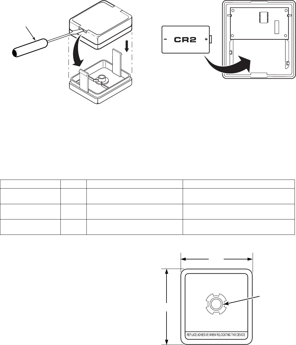
1. Using a screwdriver, release the case’s retaining tabs.
2. Carefully remove the sensor’s cover. (see Figure 2)
- 3 -
5870API-005-V0
INSERT TIP OF
SCREWDRIVER.
PUSH IN TO
RELEASE CLIP
Figure 2 – Replacing the 5870API Battery
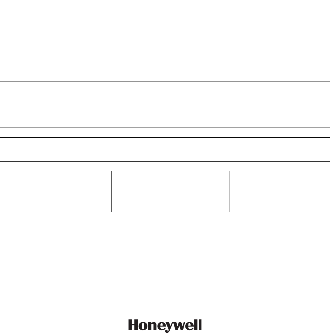
3. Check the battery polarity orientation before
installing (see Figure 3).
4. Insert the battery securely in the sensor.
5. Snap the sensor cover back in place.
5870API-001-V0
Figure 3 – Replacing the 5870API Battery
Table 1: 5870API Operating Mode Choices
SPECIFICATIONS
Dimensions:
1.8" H x 1.7" W x 0.63" D
(45.72 mm x 43.18 mm x 16.02 mm)
Power:
Single 3V Ademco 469, Panasonic CR2, Sanyo CR2,
or Duracell DLCR2 Lithium Battery
Environmental Conditions:
14° to 122°F (-10° to 50°C)
<90% RH (non-condensing)
5870API-003-V1
5870API
(Rear View)
1.8"
1.7"
TAMPER
Operating Mode Loop Faults when… Restores when…
Short Travel Time
Detection
1 Asset/sensor is moved for 1 (+1, -0)
second.
Motion of the asset/sensor has stopped for 3
(+1, -0) seconds.
Long Travel Time
Detection
2 Asset/sensor is moved for 5 (+1, -0)
seconds
Motion of the asset/sensor has stopped for 3
(+1, -0) seconds.
Open/Close Sensor 3 Asset/sensor is tilted >30 (+/-10)
degrees (with respect to the horizon)
Asset/sensor is tilted <15 (+/-5) degrees
(with respect to the horizon).
FCC & IC ID No's
WARNING
Risk of fire, explosion, and burns. Do not recharge, disassemble, heat above 212º F (100º C) or incinerate. Dispose of used
batteries properly. Keep away from children.
TO THE INSTALLER
Regular maintenance and inspection (at least annually) by the installer and frequent testing by the user are vital to
continuous satisfactory operation of any alarm system.
The installer should assume the responsibility of developing and offering a regular maintenance program to the user as well
as acquainting the user with the proper operation and limitations of the alarm system and its components parts.
Recommendations must be included for a specific program of frequent testing (at least weekly) to ensure the system’s proper
operation at all times.
FCC ID: CFS8DL5870API
The FCC ID may also be found inside the battery compartment of this product, beneath the battery. Refer to "REPLACING
THE BATTERY" above for information on how to remove the battery.
FCC and Industry Canada Statement
This device complies with Part 15 of FCC rules and RSS 210 of Industry Canada. Operation is subject to the following two
conditions: (1) This device may not cause harmful interference, and (2) this device must accept any interference received,
including interference that may cause undesired operation.
Unauthorized changes or modifications could void the user's authority to operate the equipment.
FOR WARRANTY INFORMATION AND DETAILS REGARDING THE LIMITATIONS OF THE ENTIRE
ALARM SYSTEM REFER TO THE INSTALLATION AND SETUP GUIDE FOR THE CONTROL PANEL
USED WITH THIS DEVICE.
U.S. Patent Numbers
5,155,469
5,004,999
6,724,316
7,119,681
165 Eileen Way, Syosset, New York 11791
Copyright © 2007 Honeywell International Inc.
www.honeywell.com/security
‡K14379bŠ
K14379 4/07 Rev. A