Ademco 8DL5870API1 Wireless Indoor Asset Protecction Device User Manual K14379V3 ii
Honeywell International Inc. Wireless Indoor Asset Protecction Device K14379V3 ii
Ademco >
Users Manual
K14379V3 7/11 Rev. A
5
55
5870API
870API870API
870API
Wireless Indoor Asset Protection Device
Wireless Indoor Asset Protection DeviceWireless Indoor Asset Protection Device
Wireless Indoor Asset Protection Device
INSTALLATION AND SETUP GUIDE
QUICK INSTALLATION
Peel here
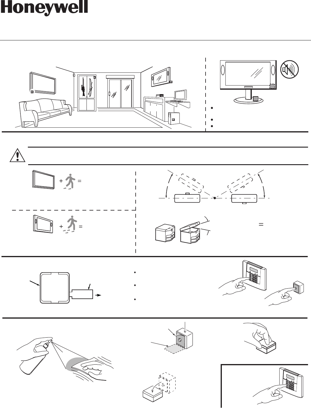
Step 1. Select Location
Step 2. Select Operating Mode (refer to table 1)
Step 5.
Test System
Step 3. Program Device (refer to Programming Section)
1-3 Seconds
30 O
Painting
Jewelry Box
LOOP 3
LOOP 3
LOOP 3
LOOP 2
LOOP 1
4. Press down firmly for 5 sec.
3. Rotate into position
Step 4. Install Device
Paintings Computers
Gun Case/Safe Large Screen
TV
2. Enter Zone Number, Zone Type,
Input Type at Keypad
Enroll Serial Number
(press tamper switch)
Enter Loop Number at Keypad
(use Loop 2 unless Fast Trigger
or Tilt is required)
30O
MOUNT HORIZONTALLY ONLY (LOOP 3 ONLY)
NORMAL
FAULT
30O
OR
Jewelry
Box
Avoid sources of vibration (i.e. speakers,
fans, motors)
Choose a stable, clean, flat surface
Mount in an inconspicuous area.
2. Peel tape backing before
installing. Place onto asset.
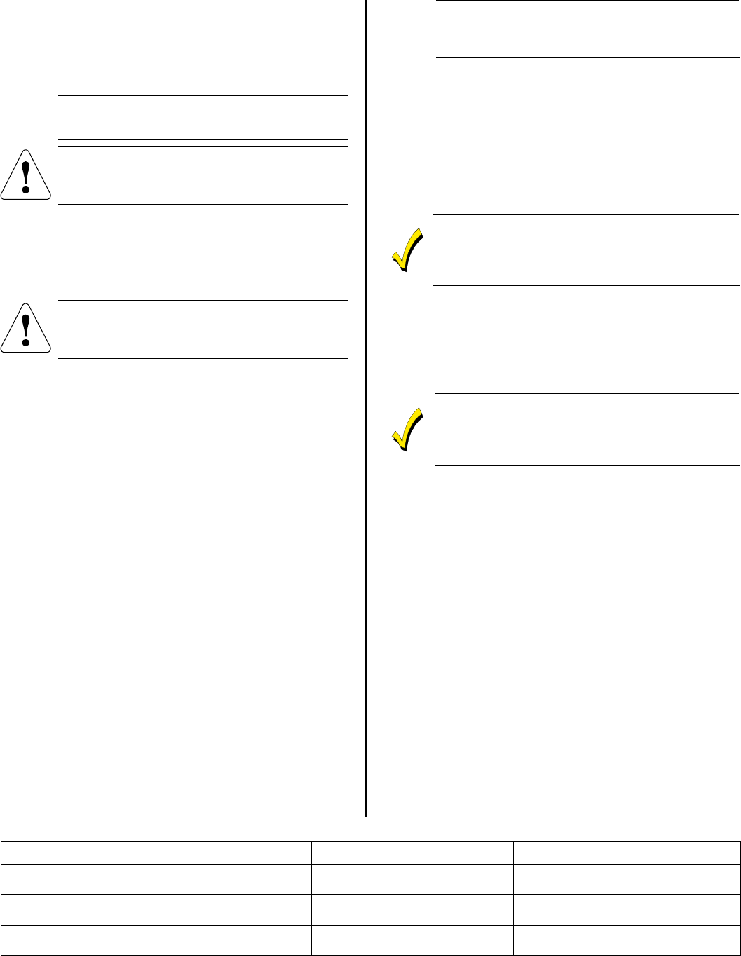
High Security (Fast Trigger) Mode (Loop 1)
Standard Security Mode (Loop 2) Tilt Mode (Loop 3)
5-8 Seconds
Large Screen
TV
(Asset)
Mounting
Surface
PULL TO CONNECT BATTERY
Pull tab
TAB
SENSOR
Greater than 30O
1. Clean mounting surface
(refer to mounting notes)
Valuables
LOOP 1 is for High Security (Fast Trigger) applications and should ONLY be used if the asset will NOT
be subject to external vibration. Loop 2 (Standard Security mode) should be used in most cases.
1. Pull tab to activate battery
PLEASE SEE BOTTOM OF
PAGE 2 FOR FCC / IC
AGENCY STATEMENTS
- 2 -
GENERAL INFORMATION
5870API is a wireless, supervised asset protection device
that is compatible with systems that support 5800 series
devices. When affixed to a high-value asset, the device
will trigger an alarm if an attempt is made to move or
disturb the asset.
UL
ULUL
UL
For commercial applications, the 5870API must be
used in conjunction with the 5881ENHC receiver
and compatible control panel.
5870API is for use on objects that do not move
frequently or vibrate. Mounting the sensor near
sources of vibration may cause false alarm
conditions to occur.
OPERATING MODES
5870API provides three programming options (loops).
• High Security (Fast Trigger) Mode (Loop 1)
• Standard Security Mode (Loop 2)
• Tilt Mode (Loop 3)
Loop 1 is for high security applications and should
ONLY be used if the asset will NOT be subject to
external vibration. Loop 2 (Standard Security
mode) should be used in most cases.
Selecting the Operating Mode
Table 1 provides a list of 5870API’s various operating
modes, with the respective Loop numbers for each.
Tamper Supervision
5870API’s tamper supervision feature (Loop 4) causes a
trouble signal to be sent to the control if the sensor is
removed from the asset being protected or if the unit’s
cover is removed from the base. The tamper switch is also
used to program the unit’s serial number and loop
assignments in the control panel.
OPERATION
Installer Test Mode- Upon initial battery power up, the
unit will transmit each time it is faulted or restored,
which enables you to enroll and test the device. After the
sensor transmits its first supervisory message (about 70-
80 minutes after power-up), it switches to normal mode.
Normal Mode - In normal mode there is a 3-minute
lockout between transmissions, to help conserve battery
life. To return to the installer test mode, remove and
reinstall the battery.
Before enrolling the device, perform the following:
1. Remove the “PULL TO CONNECT BATTERY” tab
This will allow the device to transmit. For additional
transmissions, move or rotate the sensor. When the
battery is connected the sensor powers up in the
installer test mode. In this mode the sensor transmits
fault and restore messages on all loops when it
detects motion (or lack thereof).
UL
ULUL
UL
When configured for use with the UL approved control
panels (refer to UL Approved Compatible Control
Panel list), the panel must be programmed not to
transmit off-premises for the 5870API zone only.
PROGRAMMING
Each transmitter has its own unique serial number,
assigned during manufacture, which must be “enrolled” in
the control panel before the device can be used with the
system.
Please refer to the control panel’s installation
instructions for details on device enrollment. Please
note that you must program a separate zone for each
loop you are using on the transmitter.
If the asset being protected will not be moved under
normal circumstances (i.e., a painting), it can be
programmed as a 24 hour zone type. If the asset will
occasionally be moved when the system is disarmed,
it can be programmed as a perimeter zone type.
MOUNTING
The 5870API is mounted directly to the asset being
protected via 3M VHB double-sided tape. The device
should be mounted in an inconspicuous place on the asset.
Refer to Mounting Notes section for additional
information.
When installing the 5870API, select an area on the
asset that is stable, clean and flat. Avoid areas that
are subject to vibration (i.e.; speaker grills)
When using Loop 3 the device must be mounted
horizontally.
1. Determine the optimum mounting location taking care
to avoid damp locations. To maximize the
transmitter’s range, avoid mounting the device to
metal objects, if possible.
2. Temporarily mount the device to the asset to be pro-
tected using masking tape or any suitable method.
3. Before the transmitter is permanently mounted,
conduct Go/No Go tests (refer to the Control Panel’s
instructions) to verify adequate signal strength from
the mounting location.
4. Always verify range by holding the sensor in the
approximate mounting location and moving the asset.
The panel (in test mode) should respond to the trans-
missions. If not, move the asset sensor to a more
suitable mounting location.
5. Remove the tape backing paper and firmly press the
sensor in the desired mounting location. Apply firm
pressure for 5 seconds.
6. Verify operation by moving the asset. Always check
the alarm panel keypad to verify that the zone has
tripped.
Table 1 - 5870API Operating Mode Choices
* Response time will be affected by the type of motion (walking, running, dropping, etc.) as well as other tasks being processed by the panel.
Operating Mode Loop Faults when… Restores when…
High Security (Fast Trigger) Mode - Short
Travel Time, minimum movement detection
1 Asset/sensor is moved for 1-3
seconds (typical)*
Motion of the asset/sensor has stopped
for 3 seconds*.
Standard-security Mode - Long Travel
Time, occasional movement detection
2 Asset/sensor is moved for 5-8
seconds (typical)*
Motion of the asset/sensor has stopped
for 3 seconds*.
Tilt Mode - Intended for boxes with lids that
can be opened (e.g.; jewelry or cash boxes).
3 Asset/sensor is tilted >30 degrees
(+/-10) (with respect to the horizon)
Asset/sensor is tilted <15 (+/-5) degrees
(with respect to the horizon).
- 3 -
REPLACING THE BATTERY
5870API is powered by a 3-volt lithium battery. If the
battery voltage gets too low, the device sends a low battery
signal to the control panel. The 5870API consumes less
battery power when stationary than when in motion.
Maximum battery life will be obtained when used on
assets that are moved infrequently (e.g.; televisions,
paintings, sculpture, etc.)
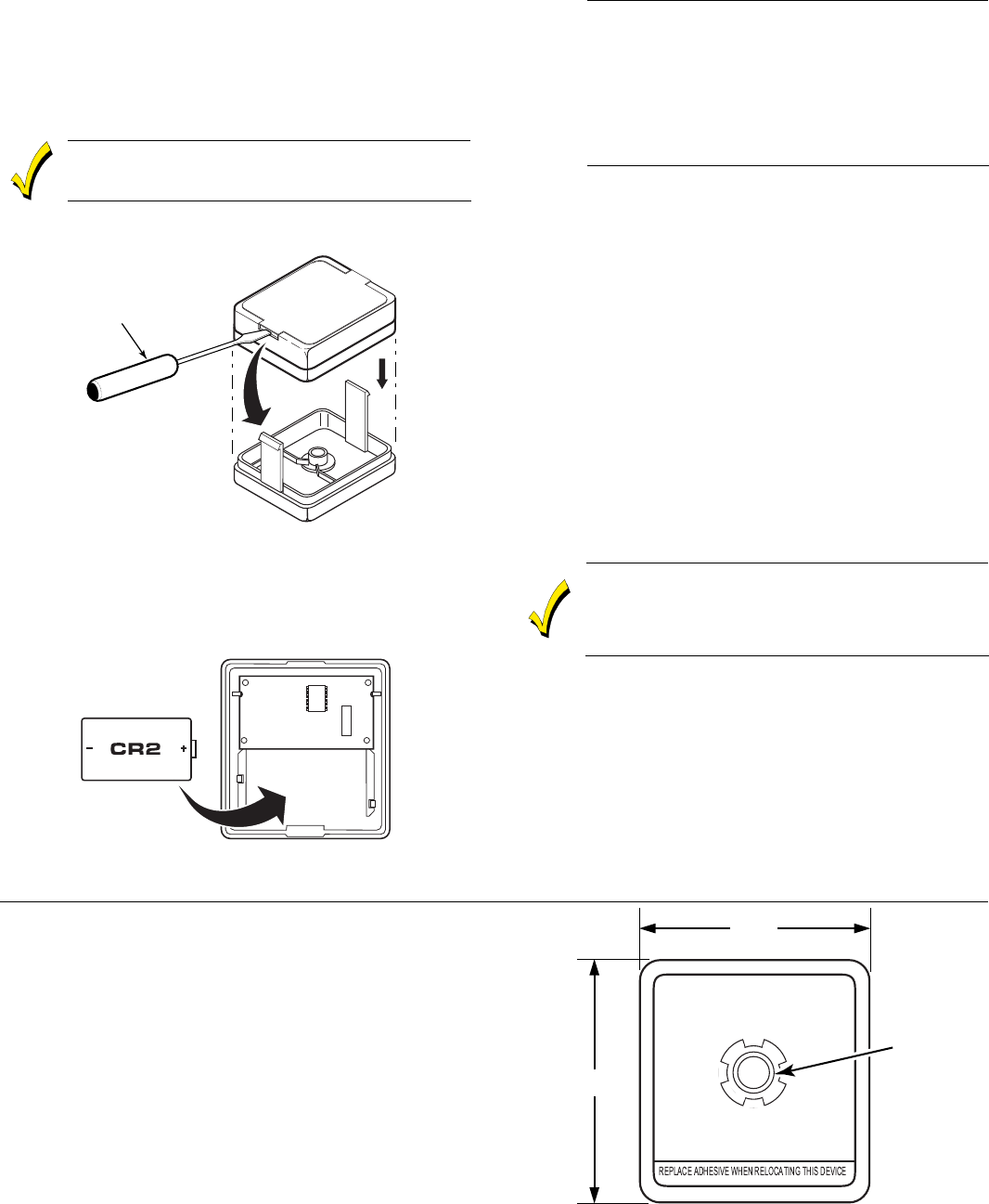
Replace the battery with Ademco 469, Panasonic CR2
or Duracell DLCR2.
Use of another battery may present
the risk of fire or explosion
1. Using a screwdriver, release the case’s retaining tabs.
2. Carefully remove the sensor’s cover. (see Figure 1)
5870API-005-V0
INSERT TIP OF
SCREWDRIVER.
PUSH IN TO
RELEASE CLIP
Figure 1 – Replacing the 5870API Battery
3. Check the battery polarity orientation before
installing (see Figure 2).
4. Insert the battery securely in the sensor.
5. Snap the sensor cover back in place.
5870API-001-V0
Figure 2 – Replacing the 5870API Battery
MOUNTING NOTES
UL
ULUL
UL
3M VHB double –sided tape can be used on the
following surfaces: acrylic, polycarbonate, coated
polycarbonate, cellulose acetate butyrate, aluminum,
acrylic/polyurethane paint, galvanized, stainless and
enameled steel, rigid PVC, epoxy, polyester and
epoxy polyester paint, uncoated and silane coated
glass, glass epoxy, polybutylene terephthalate, nylon,
noryl (PPE) polyphenelene ether, and acrylonitrile
butadiene styrene.
Note: Most consumer electronics with plastic cases are
manufactured from acrylonitrile butadiene styrene (ABS).
1. To obtain proper performance with adhesive tapes, it
is important to ensure that the surfaces are dry and
free of grease and condensed moisture. Clean the area
where the sensor will be installed with a 50/50
mixture of water and isopropyl alcohol, and allow to
dry.
2. Replace the adhesive when relocating the device. Take
care to align the hole in the tape with the device’s
tamper switch plunger. Additional mounting tape
squares are available in packs of 10; 5870APITAPE-B
general application tape.
3. Firm application pressure develops better adhesive
contact and helps improve bond strength, which is
achieved after 72 hours.
4. If using Loop 3 the device must be mounted
horizontally.
• 5870API is not watertight, and therefore should not
be used in damp locations.
• The device should not be installed in locations
where temperatures may drop below 14° F.
• 5870API is not intended for use on swinging doors.
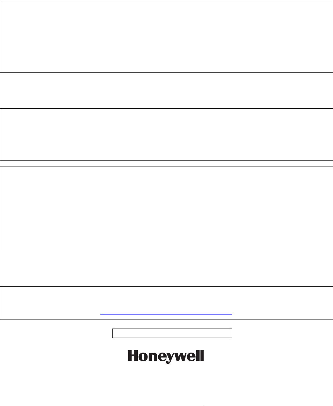
SPECIFICATIONS
Dimensions:
1.8" H x 1.7" W x 0.63" D
(45.72 mm x 43.18 mm x 16.02 mm)
Power:
Single 3V Ademco 469, Panasonic CR2 or Duracell DLCR2 Lithium
Battery
Environmental Conditions:
14° to 122°F (-10° to 50°C)
<90% RH (non-condensing)
5870API-003-V1
5870API
(Rear View)
1.8"
1.7"
TAMPER
UL APPROVED COMPATIBLE CONTROL PANELS
The 5870API is compatible with the following commercial control panel families:
Vista-10P/10PCN/10PSIA, Vista-10SE/10SEADT/10ROSE, Vista-10P1PACK, Vista-10PASE Vista-15/15CN, Vista-
15P/15PCN/ PSIA, Vista-15PMT, Vista-20BAY, Vista-20P/20PCN/20PBAY, Vista-20MT, Vista-20PS/20PSCN, Vista-20PSIA,
Vista-20SE/-20HWSE, Vista-20AMT3, Vista-40, Vista-48C/48D, Vista-50P/50PADT, Vista-50PEN/50PENADT, Vista-
128B,Vista-128BP/128BPADT, Vista-128FBP, Vista-250BP, Vista-250FBP, FA130CP/130CP-CN/130CPSIA, FA148C/148C-
CN, FA148CP/148CP-N/148CPSIA, FA168C/168C-CN/168C-GP, FA168CPS/168CPS-CN/168CPSSIA, FA1660C, FA1670C,
FA1700C, Safewatch Pro and Security Manager, Security Manager 2000, Safewatch Pro 3000/3000EN, Security Manager
3000/3000EN, Entrepreneur 3000EN, AFA15P, CFV15P/PCN, AM100, V-10SE/WT, V10SMITH, V10SELECT, V12C, 250-
P1, 300P1, 320P1
WARNING
Risk of fire, explosion, and burns. Do not recharge, disassemble, heat above 212
°
F (100
°
C) or incinerate. Dispose of used
batteries properly. Keep away from children.
TO THE INSTALLER
Regular maintenance and inspection (at least annually) by the installer and frequent testing by the user are vital to
continuous satisfactory operation of any alarm system.
The installer should assume the responsibility of developing and offering a regular maintenance program to the user as well
as acquainting the user with the proper operation and limitations of the alarm system and its components parts.
Recommendations must be included for a specific program of frequent testing (at least weekly) to ensure the system’s proper
operation at all times.
FEDERAL COMMUNICATIONS COMMISSION STATEMENT
The user shall not make any changes or modifications to the equipment unless authorized by the Installation Instructions or User’s Manual.
Unauthorized changes or modifications could void the user’s authority to operate the equipment.
FCC IC STATEMENT
This device complies with Part 15 of the FCC Rules and RSS 210 of Industry Canada. Operation is subject to the following two conditions:
(1) This device may not cause harmful interference. (2) This device must accept any interference received, including interference that may
cause undesired operation.
Cet appareil est conforme à la partie 15 des règles de la FCC & de RSS 210 des Industries Canada. Son fonctionnement est soumis aux
conditions suivantes : (1) Cet appareil ne doit pas causer d'interférences nuisibles. (2) Cet appareil doit accepter toute interférence reçues,
y compris les interférences causant un reception indésirable.
FCC ID: CFS8DL5870API1 IC: 573F-5870API1 IC MODEL: 5870API1
WARRANTY INFORMATION
For the latest warranty information, please visit:
www.honeywell.com/security/hsc/resources/wa
U.S. Patent Number
6,724,316
2 Corporate Center Drive, Suite 100
P.O. Box 9040, Melville, NY 11747
Copyright © 2011 Honeywell International Inc.
www.honeywell.com/security
ÊK14379V3rŠ
K14379V3 7/11 Rev. A