Ademco 8DL6152RF Keypad Transceiver User Manual 800 11537 A 6152RF ig 04 12 13
Honeywell International Inc. Keypad Transceiver 800 11537 A 6152RF ig 04 12 13
Ademco >
Users Manual
ADEMCO 6152RF Keypad / Transceiver – Installation and Setup Guide
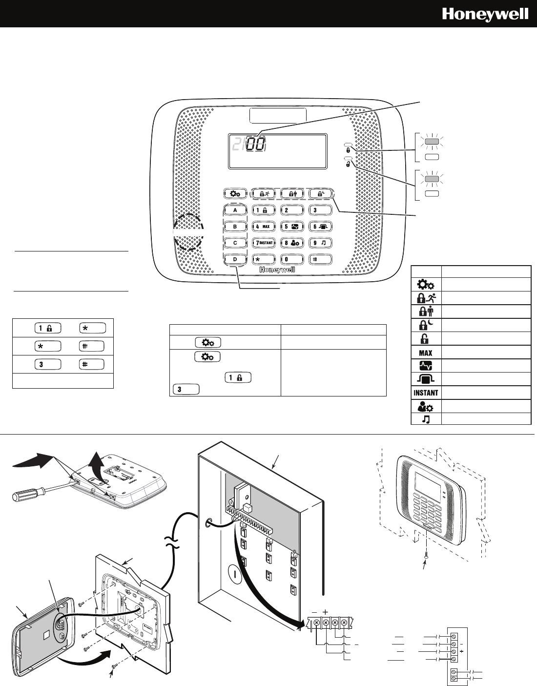
Fixed Addressable Keypad/Transceivers for use with Honeywell Control Panels; incorporates normally-open
relay output with the functions of a medium 16 zone RF Receiver and a 5800 Transmitter module.
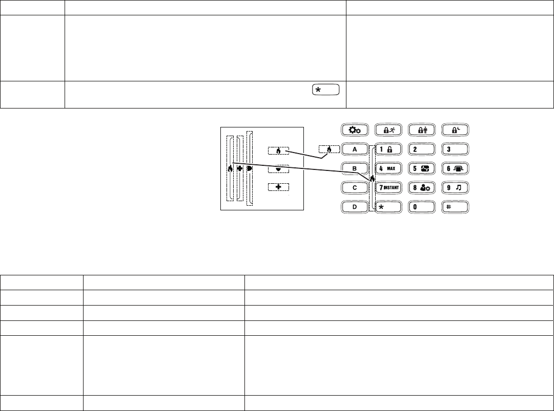
= READY to Arm
= NOT READY to Arm
= System ARMED
= System NOT ARMED
Programmable Function Keys
Arming Keys
6152RF: Fixed Word Display
2-Digit Zone Identifier
The ‘21’ digits are used for specific
trouble indications. Refer to the
control panel instructions for details.
ALARM
FIRE
AWAY
BYPASS
STAY
CHECK
INSTANT CANCELED
NO NIGHT AC
NOT READY
CHIME BAT
TESTPHONE
6152RF-KEYPAD-LBLD-032613
Sounder
Wall
Surface
2
1
SEE Detail A
Optional Front Cover Securing Screw
(Required in European Installations)
Install Four (4)
Mounting Screws
Control Panel
1. OPEN
Keypad
Front
Cover
2. WIRE
3. MOUNT
• Connect only one wire per terminal.
• For Daisy-Chain Configurations, use
wire splicing so only one wire is
connected to each terminal.
Mount on drywall, or in a single
or double-gang electrical box.
AUX
RELAY OUTPUT
CONNECTIONS
[ ] GROUND
[Y] DATA IN
[+] +12VDC IN
[G] DATA O U T
Yellow
Black
Red
Green
CONTROL PANEL
TERMINAL STRIP
16-24 AWG Only
KEYPAD
NO
C
DATA
IN
DATA
OUT
AUX
Detail
A
G
Y
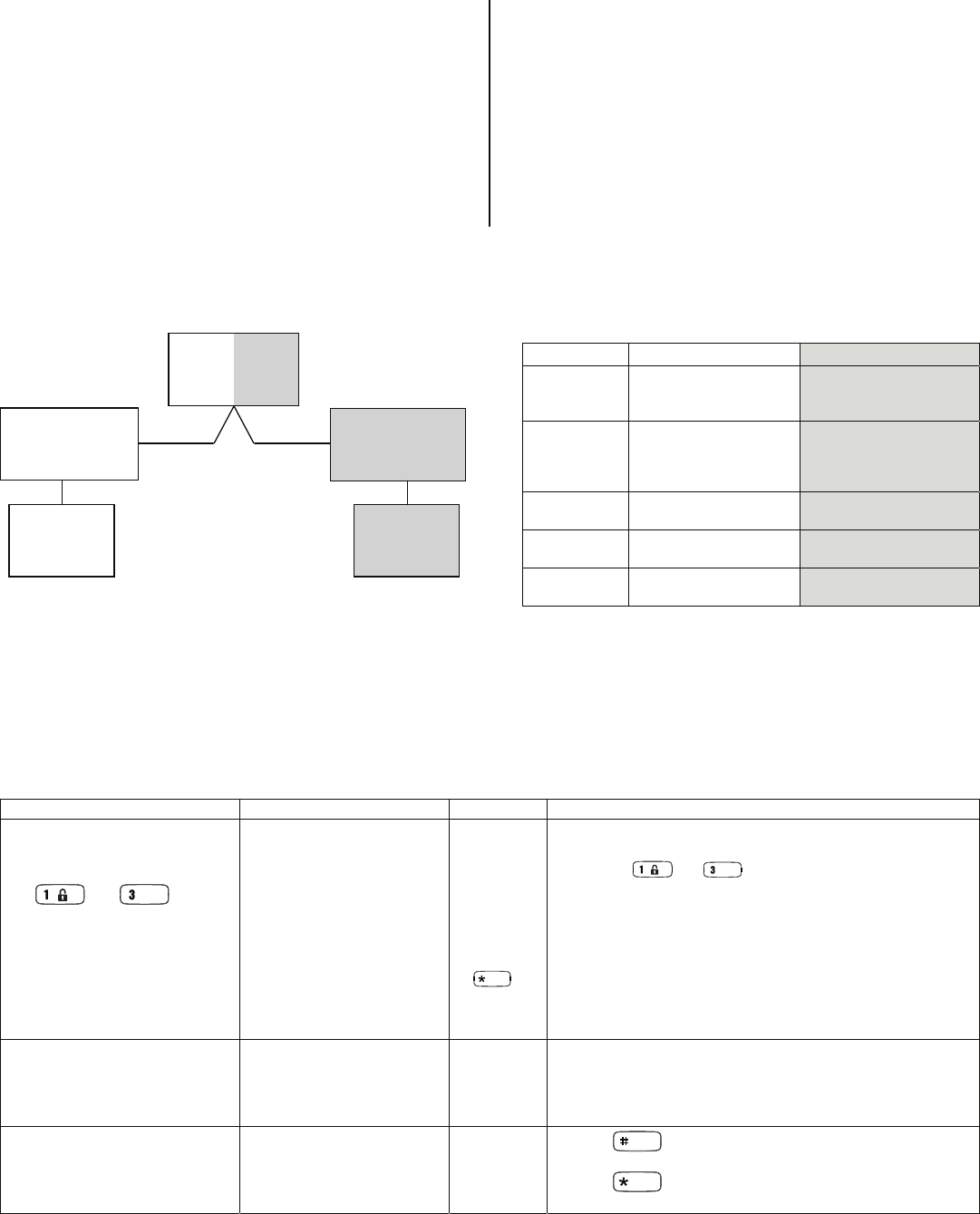
To activate Function keys,
press and hold key for at
least 2 seconds; key pairs
are activated immediately.
Table 1 – Programmable
Function Keys
A or and
B or and
C or and
D
Note: See the control’s instructions for
details on programming the Function
keys for panic alarms or other special
functions (i.e., macros).
Programmable to support the
following :
- Bi-directional 5828/5828V
wireless keypads and wireless
keys (e.g., 5804BDV, 5834-4,
etc.)
- Up to eight button-type wireless
keys locally (programmed
directly into the keypad),
without occupying control panel
zones
- Up to 16 5800 series wireless
zones programmed into any
supported control panel
- Wireless keys with high security
mode enabled
Table 3 – Icon Descriptions
ICON DESCRIPTION
TEST SYSTEM
BYPASS ZONES
ASSIGN CODES
CHIME MODE
ARM MAXIMUM
ARM INSTANT
ARM AWAY
ARM NIGHT STAY
DISARM
ARM STAY
SETTINGS
Table 2 – Settings Ke
y
Settings Ke
y
Result
Press for 2 Seconds Enters Display Test Mode
Press for 2 Seconds
and during the Display Test,
press and hold and
for 3 Seconds
Reboots the Keypad (the
keypad beeps and the ARM
and READY LED’s flash for
several seconds)
PLEASE GO TO
PAGE 7 FOR
THE AGENCY
STATEMENTS
- 2 -
INSTALLATION AND APPLICATION GUIDELINES
For installation, consider the following:
• Locate the 6152RF in an area and at a height convenient for
user operation.
• The 6152RF must be at least 10 feet from the control panel
to ensure proper RF receiver operation.
• Local wireless keys (wireless keys programmed directly into
the 6152RF) may be used regardless of whether the RF
receiver in the 6152RF is enabled or disabled.
• If using bi-directional devices, be sure to enable the
transmitter module in the 6152RF (program address 7).
• If transmitters are programmed into the control panel, be
sure to enable the receiver (program address 6). (Do not
exceed the number of receivers supported by the control
panel.)
• If a local wireless key is programmed to arm/disarm or to
trigger a relay on the control panel, a user code must be
entered into the 6152RF. This user code must also be
programmed into the control panel.
• You must set the House ID only if you are using RF keypads
and/or bi-directional devices; AND the House ID Source is
the 6152RF (Local).
Partition Installation Example
An example of an installation using two 6152RF Keypad / Transceivers with 2-Way Wireless Devices (e.g., 5828V) on two Partitions is
shown below:
6152RF
Partition #1
System House ID = 1
6152RF
Partition #2
Local House ID = 2
5828 or 5804BD
Partition #1
House ID = 1
5828 or 5804BD
Partition #2
House ID = 2
CONTROL
PANEL
Partition #1 Partition #2
Table 4 – Partition Installation
Settings 6152RF #1 6152RF #2
Keypad: Must be assigned to
Partition 1 in the
control panel
Must be assigned to
Partition 2 in the control
panel
House ID: Match Partition 1
House ID in the control
panel and House ID in
Wireless Device
Match House ID in
Wireless Device
House ID
Source:
System Local
Receiver
Enable:
On Off
Transmitter
Enable:
On On
4. PROGRAM
To program the keypad, first enter the Programming Mode, select a programming address and set the programming options. Refer to
the tables below and on the following pages for details on entering Programming mode, default values and programming choices for
each option.
Table 5 – Programming Mode
Action Result Displa
y
Notes
1. Enter Program Mode
Within 30 seconds of power up
or reboot, press and hold down
the and keys at
the same time for 3 seconds.
Note: Refer to Table 2 to reboot
the keypad.
Enters the Program mode
at the Start screen and
the keypad beeps three
(3) times
oo, - -
flash
alternately
[If any other
numbers or
letters
appear
press
.)
- The keypad will not enter programming mode if the panel is
armed.
- Press the and keys 60 seconds or more after
power up to enter the User mode. This mode allows individual
local wireless keys to be enabled and disabled (useful if, e.g., a
user accidentally loses a wireless key). Refer to the User
Guide for instructions.
- To enter keypad Programming mode after power up period,
reboot the keypad (see Table 2 on page 1) and try again
after the keypad LED’s stop flashing.
- The keypad automatically exits the Program mode if no keys
are pressed for 90 seconds.
2. Enter a Programming
Address
(See Program Address
column in Table 6)
Screen displays selected
programming address
See
Display
column in
Table 6.
- (For example, enter [1] to go to Keypad Address; enter [2]
to go to Receiver Address).
3. Set programming options
Use the number and
navigation keys to set the
programming options.
Refer to Choices column
in Table 6.
- Press to erase the current information and move
back.
- Press to store the displayed information, the keypad
beeps twice and the screen returns to Start

- 3 -
Table 6 – Programming Options
After editing any programming address, pressing will save the displayed information and return to the Start screen.
Enter
Program
Address
Moves to Address
Description Display Choices Default Notes
Enter [1] Keypad Address cA 00-311 16
Enable keypad address in the
Control panel.
Enter [2] Receiver Address rA 00-302 00
Enter [3] House ID
Only needed if RF keypads
and/or bi-directional units are
used and House ID source is
set for Local.
hI 00-31 10 The House ID entered here
MUST match the House ID
programmed in the RF
keypad and the bi-directional
unit.
Enter [4] House ID Source hS 1 = System
0 = Local
1 (System) System uses the House ID
programmed in the control.
Local uses the House ID
programmed in the keypad.
Enter [5] Wireless Key Editing d- Enter Existing Device
Number (1-8)
Enter [6] Receiver Enable
Enable the receiver if RF
transmitters or wireless
keypads are programmed into
the control.
rE 1 = On (Enable)
0 = Off (Disable)
1 (Enable) If enabled, the number of
receivers cannot exceed the
control panel capacity.
Enter [7] Transmitter Module Enable
Enable if using bi-directional
devices.
tE 1 = On (Enable)
0 = Off (Disable)
1 (Enable) Enable Transmitter Module in
only one keypad if more than
one 6152RF is used and the
House ID source is ‘System’.
Enter [8] Wireless Key Auto Enroll
See Programming Local Wireless Keys
for Address 8 programming details
Wireless Key User Code
Wireless Key Loop
Function
Wireless Key On-Board
Relay Assignment
Enter [9] Restore Defaults EE 1 = Restores Defaults
Any Other Key = Does
Not Restore Defaults
Enter [0] High Security Mode† En 1 = Enable;
0 = Disable
0 Disable
Enter [A] User Code u4 Enter 4-Digit User Code
(0000 – 9999)
This user code will be used to
enable the single button
arming keys. Must be a valid
user code programmed in the
control.
1 For VISTA-10P/15P/20P/21IP use Keypad Addresses 16-23; For VISTA-40/50P/128/250 use Keypad Addresses 00-30
2 For VISTA-10P/15P/20P/21IP use Receiver Address 00; For VISTA-40/50P/128/250 use Receiver Addresses 01-30 and enable the receiver address in
the Control panel.
† When operating the system in High-Security mode, non-encrypted wireless keys will not function.
Upon exiting the Program mode, the 6152RF alternately flashes "Ad," the 2-digit keypad address, and the 2-digit receiver address. If
either of these is incorrect, enter Program Mode again and reset the address(es) (see Tables 5 and 6).
- 4 -
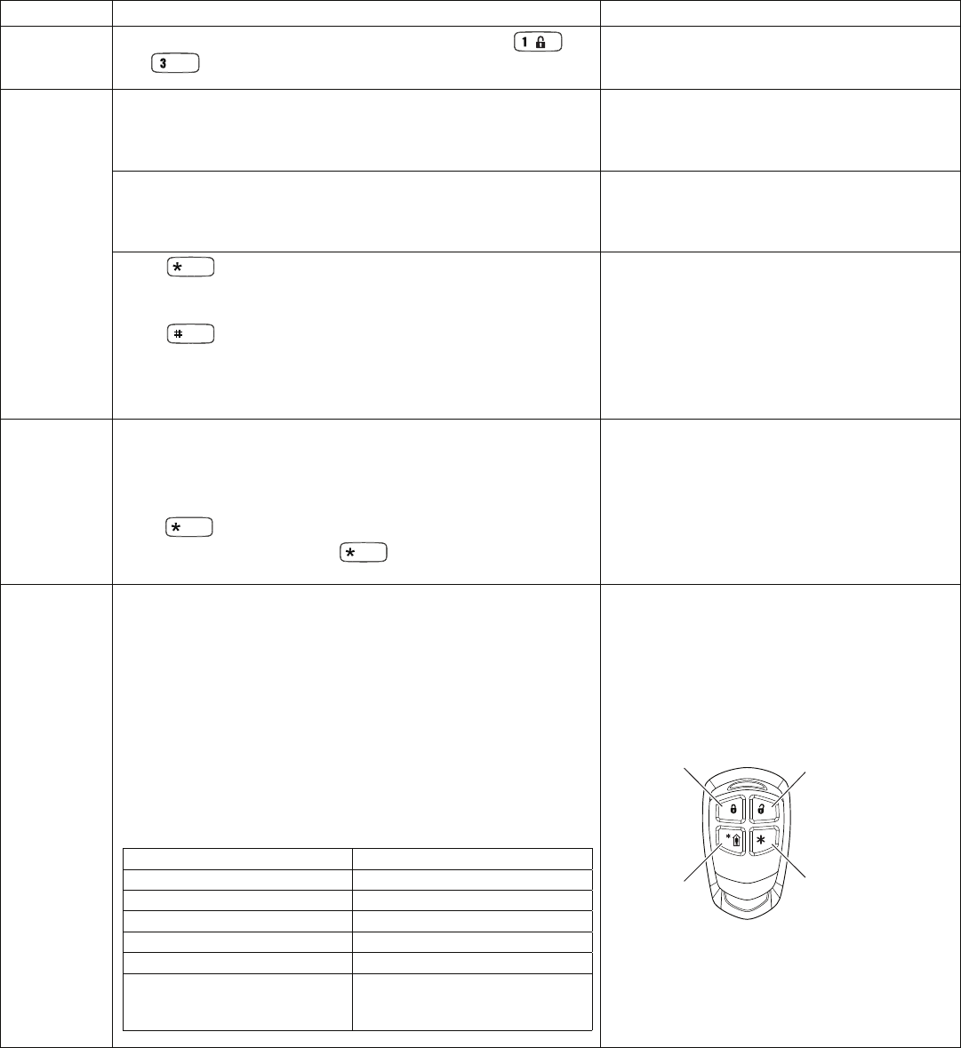
PROGRAMMING LOCAL WIRELESS KEYS
This section is for first time enrolling and setup of wireless keys. To edit or delete a wireless key that is already enrolled; refer to the,
Deleting, Replacing or Editing Wireless Keys section.
Table 7 – Wireless Keys Programming
Step Action Display
Enter
Program
Mode
Within 30 seconds of power up, press and hold down the
and keys at the same time for 3 seconds.
"oo, - -" flash alternately
See Table 5 for more details.
Enter [8] Wireless Key Auto Enroll. The 6152RF automatically advances
to first available device number.
Note: If all 8 devices have been enrolled, the 6152RF beeps three times
and continues to alternately flash "oo" and "- -."
Flashes "d" with the next available device
number; followed by "- -" (four times) and then
repeats the sequence.
Press any button on the wireless key to enroll the serial number.
The keypad will beep three times.
Note: If enrolling a wireless key in high security mode, see the Installation
Instructions for that Model for further information.
Alternately flashes "d" with the device number
and the serial number.
Press to accept the serial number; the 6152RF beeps two
times.
OR
Press to reject the serial number; the 6152RF beeps once
and returns to the “enroll serial number” prompt.
Note: A maximum of 8 wireless keys may be enrolled into the 6152RF.
These wireless keys DO NOT occupy any zones supported by the
control.
If you accept the serial number, the display
flashes the device number and a hyphen.
If you reject the serial number, the display
flashes "d" with the device number followed by
"- -" four times.
Enter [2]
Wireless Key User Code. Enter the 4-digit user code for the
wireless key.
Note: The user code must be a valid code that is programmed in the
control panel. If the code is deleted or changed in the control, the
wireless key will no longer work.
Press to accept the user code.
If finished programming, press to exit. Otherwise, continue
programming as noted below.
Flashes "u4." Once the 4-digit user code is
entered, the display flashes "u4," the first two
digits, and then the last two digits of the user
code.
Enter [4]
Wireless Key Loop Functions. Enter the loop number (1-4).
The 6152RF is shipped with the loop functions pre-programmed
(see illustrations in the next column):
Loop 1 Close the 6152RF On-Board Relay for 2 sec.
Loop 2 1 (Disarm)
Loop 3 2 (Arm Away)
Loop 4 3 (Arm Stay)
To change any of the loop functions enter one of the choices
listed in the Wireless Key Function Chart below.*
* Entering a number other than the one specified may give unpredictable
results.
Wireless Key Function Chart
Function Entry
Disarming 1
Arming Away 2
Arming Stay 3
Arming Maximum (Away Instant) 4
Arming Instant 7
Panic Alarm
Produces type of alarm [* & #]
programmed in control panel.
# + 99
Flashes "Ln."
Once the loop number is entered, alternately
flashes "L" with the loop number; and the
present function.
Default Loop Functions
LOOP 3
Arm AWAY
LOOP 1
Close on-board relay
for 2 seconds
LOOP 2
Disarm
5834-4 / 5834-4EN
LOOP 4
Arm STAY
- 5 -
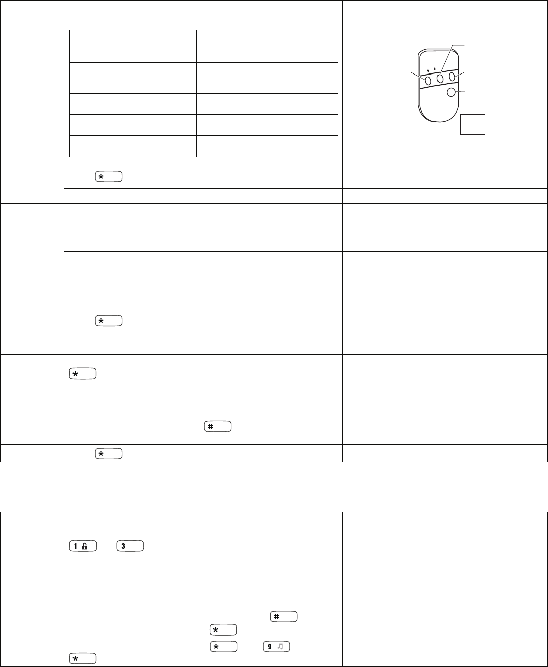
Table 7 – Wireless Keys Programming (continued)
Step Action Display
(Cont’d)
Wireless Key Function Chart (continued)
Manually Start a Relay Action
# + 7 (VISTA-SE Panel)
# + 7 + n (VISTA-10P, VISTA-15P,
VISTA-20P, VISTA-21ip)
Manually Stop a Relay Action
# + 8 (VIST
A
-SE Panel)
# + 8 + n (VISTA-10P, VISTA-15P,
VISTA-20P, VISTA-21ip)
Activate Relay as Programmed
in Control
# + 71 (VISTA-40, VISTA-50P,
VISTA-128/250)
Activate Relay as Programmed
in Control
# + 72 (VISTA-40, VISTA-50P,
VISTA-128/250)
Activate Access Control Relay
for Partition
0 (VISTA-40, VISTA-50P, VISTA-
128/250)
n = Device Number programmed in panel to be controlled
Press to save function setting.
Default Loop Functions (continued)
•
•
••
•
•
•
•
•
•
•
•
•
•
•
•
•••
LOOP 3
Arm AWAY
LOOP 4
Arm STAY
LOOP 1
Close on-board relay
for 2 seconds
LOOP 2
Disarm
5804BD / 5804BDV
SET
HOUSE
CODE
Note: If the loop is defaulted with a function (e.g.,
Arm, Disarm) and also is assigned to activate
the on-board relay, the system performs BOTH
functions.
Repeat this process for the rest of the wireless key loops.
Enter [5]
Wireless Key On-Board Relay Assignment. Program a button
on the wireless key to control the on-board relay.
Note: Any button can control the on-board relay in addition to performing
one of the Loop functions above.
Flashes "o-"
Enter the loop number of the wireless key (1-4).
Enter the desired relay action:
0 = no action 3 = relay toggles on and off
1 = relay off 4 = relay closes for 2 seconds
2 = relay on
Press to save the relay assignment.
Flashes "o" and the loop number.
Once the action is entered, alternately flashes
"o" and the loop number and the relay action
(e.g., alternately flashing “o3” and “4” shows
Loop 3 will close the relay for 2 seconds.)
Repeat for the wireless key loops where on-board relay control is
desired.
When all loops have been programmed for the wireless key, press
.
Flashes "d" followed by the device number.
The 6152RF automatically displays the next available device
number (one that does not have a serial number).
d1 – d8
If you want to program additional wireless keys, repeat the
previous steps. Otherwise, press to return to the
Programming Start screen
"oo" and "- -" flash alternately
Press to exit the 6152RF Program mode.
DELETING, REPLACING, OR EDITING WIRELESS KEYS
Use the following procedure to make changes to wireless keys.
Table 8 – Deleting, Replacing or Editing Wireless Keys
Step Action Display
Enter
Program
Mode
Within 30 seconds of power up or reboot, press and hold down the
and keys at the same time for 3 seconds.
"oo, - -" flash alternately
Enter [5]. Wireless Key Editing
Enter the device number for the wireless key you want to edit (1-
8). This must be a device that has its serial number already
programmed in the 6152RF.
To exit without editing the wireless key, press the key.
To edit the wireless key, press the key to continue.
Flashes "d-".
Once the device number is entered, alternately
flashes "d" with the device number; and the
serial number.
Delete To delete the serial number, press , then , and press
again.
- 6 -
Table 8 – Deleting, Replacing or Editing Wireless Keys (continued)
Step Action Display
Edit To change any of the programming for the wireless key, refer to
the procedures described in Table 7 for the following changes:.
• To edit the user code, see "Enter [2]"
• To edit the loop functions, see "Enter [4]"
• To edit the on-board relay assignment, "Enter [5]"
Alternately flashes "d" with the device number;
and "-."
u4
Ln
o-
Exit When you have completed editing the wireless keys, press
twice to exit the Program mode.
FUNCTION KEY LABELS
A set of adhesive-backed labels with some typical
function symbols (fire, police, personal emergency)
is provided. These labels can be placed next to the
keys to identify each key's function for the end user
(as determined by the control panel's capability and
programming; see the control's instructions).
TROUBLESHOOTING
The following error messages cause the 6152RF to produce rapid beeps for 5 seconds. The table below describes the error messages
and the corrective actions.
Table 9 – Troubleshooting
Display Probable Cause Corrective Action
Lb Low battery in the wireless key 1. Replace the battery in the wireless key.
OC Open circuit Verify that the Data Out wire is connected properly.
1C Incompatible connection Verify that the control panel is not a First Alert-type control panel.
Check 09 OR
Check 100 OR
Check 10n*
1. 6152RF Receiver is not
communicating
2. Another device on the keypad
terminals conflict with this
receiver address.
1. Verify that the Data In wire is connected properly.
2. Verify no other devices on the keypad bus are set for receiver
address.
E8 Too many RF zones programmed Verify the number of transmitters programmed into the control panel
*n = receiver address programmed in VISTA control panel
SPECIFICATIONS
Physical: 4.88"H x 6.934"W x 1.02"D
Displays: Fixed-Word LCD (backlit).
Sounder: Piezo-electric [fire alarm is loud, pulsing single
tone; (all Keypads) burglary alarm is loud,
continuous, dual tone].
Range: 200’ nominal.
Frequency: 345 MHz
Wiring: Refer to Installation diagram on page 1.
Voltage: 12VDC (power-limited)
Relay: Normally-Open, 1 A, 28VDC
Current: 105mA (ARMED LED lit, LCD backlight and
sounder on), reduces to 80mA when panel is
operating in standby mode (backlight off).
NFPA-72: Compliant
61x2-FUNCT-KEY-LBLS-041113
PANIC ALARM STICKERS
800-13067-02

FEDERAL COMMUNICATIONS COMMISSION STATEMENT:
The user shall not make any changes or modifications to the equipment unless authorized by the
Installation Instructions or User Manual. Unauthorized changes or modifications could void the
user's authority to operate the equipment.
CLASS B DIGITAL DEVICE STATEMENT
This equipment has been tested to FCC requirements and has been found acceptable for use.
The FCC requires the following statement for your information:
This equipment generates and uses radio frequency energy and if not installed and used
properly, that is, in strict accordance with the manufacturer's instructions, may cause interference
to radio and television reception. It has been type tested and found to comply with the limits for a
Class B computing device in accordance with the specifications in Part 15 of FCC Rules, which
are designed to provide reasonable protection against such interference in a residential
installation. However, there is no guarantee that interference will not occur in a particular
installation. If this equipment does cause interference to radio or television reception, which can
be determined by turning the equipment off and on, the user is encouraged to try to correct the
interference by one or more of the following measures:
• If using an indoor antenna, have a quality outdoor antenna installed.
• Reorient the receiving antenna until interference is reduced or eliminated.
• Move the radio or television receiver away from the receiver/control.
• Move the antenna leads away from any wire runs to the receiver/control.
• Plug the receiver/control into a different outlet so that it and the radio or television receiver are
on different branch circuits.
• Consult the dealer or an experienced radio/TV technician for help.
INDUSTRY CANADA CLASS B STATEMENT
This Class B digital apparatus complies with Canadian ICES-003.
Cet appareil numérique de la classe B est conforme à la norme
NMB-003 du Canada.
FCC / IC STATEMENT:
This device complies with Part 15 of the FCC Rules, and RSS 210 of
Industry Canada (IC). Operation is subject to the following two
conditions: (1) This device may not cause harmful interference (2)
This device must accept any interference received, including
interference that may cause undesired operation.
Cet appareil est conforme à la partie 15 des règles de la FCC & de
RSS 210 des Industries Canada. Son fonctionnement est soumis aux
conditions suivantes: (1) Cet appareil ne doit pas causer d'
interferences nuisibles. (2) Cet appareil doit accepter toute interference
reçue y compris les interferences causant une reception indésirable.

REFER TO INSTALLATION INSTRUCTIONS FOR THE CONTROL PANEL WITH WHICH THIS DEVICE IS USED FOR WARRANTY
INFORMATION AND LIMITATIONS OF THE ENTIRE ALARM SYSTEM.
WARRANTY INFORMATION: For the latest warranty information, please go to www.honeywell.com/security/hsc/resources/wa
DOCUMENTATION AND ONLINE SUPPORT: For the latest documentation and online support information, please go to:
http://www.security.honeywell.com/hsc/resources/MyWebTech
Ê800-11537:Š
800-11537 4/13 Rev. A
2 Corporate Center Drive, Suite 100
P.O. Box 9040, Melville, NY 11747
Copyright © 2013 Honeywell International Inc.
www.honeywell.com/security