Ademco 8DL6160RF-2 Security Transceiver / Keypad User Manual K0903V1 E 6160RF ii
Honeywell International Inc. Security Transceiver / Keypad K0903V1 E 6160RF ii
Ademco >
Users Manual
K0903V1 2/06 Rev. E
ADEMCO 6160RF
ADEMCO 6160RFADEMCO 6160RF
ADEMCO 6160RF
Keypad/Transceiver
Keypad/TransceiverKeypad/Transceiver
Keypad/Transceiver
Installation and Setup Guide
Installation and Setup GuideInstallation and Setup Guide
Installation and Setup Guide
GENERAL INFORMATION
The ADEMCO 6160RF keypad/transceiver is a combination unit that combines the functions of the following
devices:
• 6160 Alphanumeric Addressable Keypad
• 5881H RF Receiver
• 5800TM Transmitter Module
The 6160RF Keypad/Transceiver may be used on any control panel that supports 5800 Series wireless devices
(e.g., VISTA-10P, VISTA-15P, and VISTA-20P).
FEATURES
• Supports wireless key transmitters (e.g.; 5804) and bi-directional transmitters (e.g.; 5804BD, 5828/5828V).
• Supports wireless keys with high-security (encryption) capability (e.g.; 5804E, 5834-4).
• Provides a nominal range of 200 feet for RF transmitters (some transmitters have a shorter range).
• Supports RF jam detection when the receiver is enabled.
• Capable of sending status signals (Armed, Ready, etc.) to bi-directional units such as 5804BD, 5804BDV and
5828/5828V.
U
UU
UL
LL
L The following 5800 series transmitters are not intended for use in UL installations: 5802, 5804, 5804BD, 5804BDV, 5804E,
5814, 5819, 5819BRS, 5819WHS, and 5828/5828V.
INSTALLING THE 6160RF
Locate the 6160RF in an area and at a height where
it is convenient for user operation. The 6160RF must
be at least 10 ft from the control panel to ensure
proper operation of the RF receiver.
Mounting and Wiring
The 6160RF has terminal blocks for connection to
power and data wires. Removing the keypad’s case
back provides access to the terminal blocks.
The 6160RF can be surface mounted directly to
walls, or to a single- or double-gang electrical box.
Follow these steps to mount and wire the keypad:
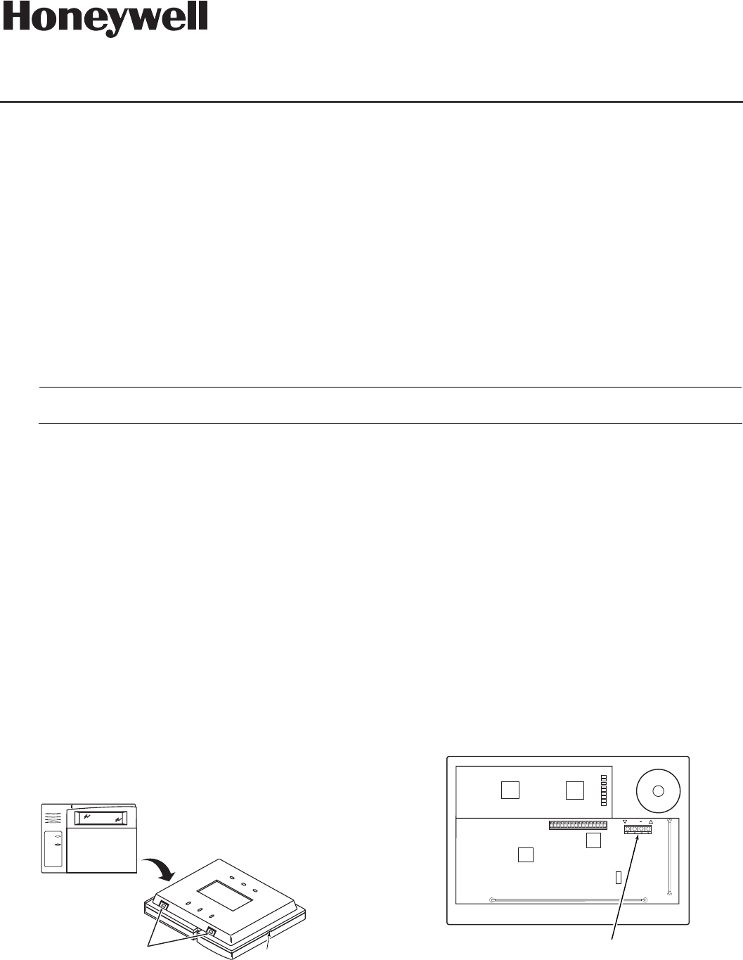
1. Push the two case release snaps at the bottom of
the keypad with the blade of a medium
screwdriver (this will push in the release snap),
then pull that side of the case back away. Insert
the screwdriver in the side of the keypad
(between the front and back case) and gently
twist to release the side locking tab. Repeat for
the other side. Refer to Figure 1 for location of the
case back release snaps and locking tabs.
ARMED
READY
MOUNTING
RELEASE
SNAPS
NOTE:
TO REMOVE REAR COVER
PUSH IN THE TWO MOUNTING
SNAPS LOCATED ALONG THE
BOTTOM OF THE KEYPAD
AND LIFT COVER UP.
6160RF-003-V1
LOCKING
TA B
Figure 1. Removing the Case Back
2. Pass the wiring from the control panel through
the opening in the case back. (see the control
panel’s instructions for proper run lengths.)
a. If surface wiring is being used, wiring may be
routed through the top or the bottom left-side
breakout in the case back. The breakouts must
be punched out using a screwdriver before
mounting the case back.
b. If desired, wires may be strain-relieved to the
wire tie point on the inside of the case back
with a tie wrap (not supplied).
3. Mount the case back to a wall or to an electrical
box using the 25mm-long self-tapping screws
supplied (mollies for drywall are not supplied).
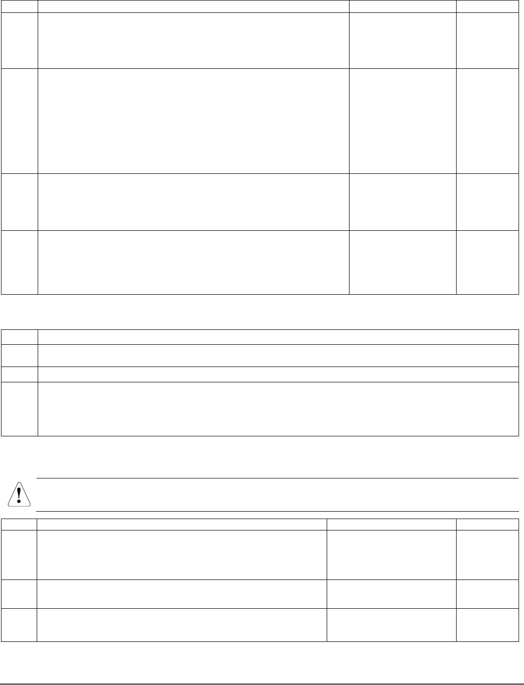
4. Connect the power and data wires from the
control panel to the terminals on the 6160RF as
indicated in Figure 2 and Table 1.
G
6160RF-002-V1
Y+
WIRING TERMINALS
(TO CONTROL PANEL)
+
+
+
+
Figure 2 - 6160RF Wiring Details
FCC / IC AGENCY
STATEMENTS ARE
ON PAGE 4

- 2 -
Table 1 - Wiring Table
Keypad Control Panel Wire Color
G▼ (Data Out) Data In Green
- -Aux Pwr (GND) Black
+ +Aux Pwr Red
▲Y (Data In) Data Out Yellow
5. Reattach the keypad to the mounted case back.
Attach the top of the keypad first, and then
press the bottom section down until it snaps
into place securely.
6. Peel off protective film on the LED panel and
install the keypad labels as required.
APPLICATION GUIDELINES FOR THE 6160RF
Use the following guidelines when planning an installation:
If… And… Then…
This is the only
transceiver on
the system,
You want to use both
the receiver and
transmitter function
on a single-partition
system,
• Set the keypad to a device address assigned to the desired partition.*
• Enable the receiver.
• Program a system House ID in the control panel (this will enable the transmitter
function).**
• Set the wireless devices that will communicate with this 6160RF to the same
system House ID.
You want to use only
the transmitter
function on a second
partition,
• Set the keypad to a device address assigned to the desired partition.*
• Disable the receiver.
• Program a DIFFERENT House ID in the 6160RF than is programmed in the control
panel.*/ **
• Set the wireless devices that will communicate with this 6160RF to the same
House ID as the 6160RF.
There is another
receiver or
transceiver on
the system,
You want to use only
the transmitter
function on a single-
partition system,
• Set the keypad to a device address assigned to the Partition 1.
• Disable the receiver.
• Program a House ID in the 6160RF that matches the system House ID
programmed in the control panel.*
• Set the wireless devices that will communicate with this 6160RF to the same
House ID.
Notes:
* On VISTA-40 panels and above, wireless keypads (e.g., 5804BD) can only be used on a single partition. This
partition is programmed in field 1*48, and must match the partition assigned to the 6160RF. Wireless keys can
be used on more than one partition, using a House ID programmed in the 6160RF and the devices. In this case,
the wireless keys must be assigned to the same partition as the 6160RF.
** On VISTA-20P panels, the 6160RF will use the House ID programmed in the panel for the partition to which
it is assigned. Wireless keypads can only be used on Partition 1.
PROGRAMMING THE 6160RF
Refer to the following procedure to program the 6160RF:
STEP DESCRIPTION DISPLAY CHOICES
1. Enter the program mode by pressing the [1] and [3] keys simultaneously
for a few seconds within 60 seconds after applying power.
2. (Keypad Address) Enter the two-digit keypad address. Press the [✻] key
to continue.
Notes: (1) Refer to the control panel’s installation instructions for the
acceptable keypad addresses.
(2) On the VISTA-40 and above the 6160RF’s partition assignment must
match the RF keypad partition assignment programmed in field
(1*48).
CON ADDRESS
CON ADDRESS CON ADDRESS
CON ADDRESS
=
XX
XX XX
XX
00-31
3. (Receiver Enable) Enter [1] to enable, or [0] to disable Receiver. Enable
the receiver if RF transmitters or wireless keypads are programmed into
the control and no other receivers are enabled. Press the [✻] key to
continue.
RECEIVER
RECEIVERRECEIVER
RECEIVER
ON [0
ON [0ON [0
ON [0
=
OFF]
OFF] OFF]
OFF]
1= ON
0 = OFF
- 3 -
STEP DESCRIPTION DISPLAY CHOICES
4. (Receiver Address) If receiver is enabled, enter the two-digit receiver
address. (00-30).
Note: Refer to the control panel’s installation instructions for the acceptable
receiver addresses.
Press the [✻] key to continue.
REC ADDRESS
REC ADDRESSREC ADDRESS
REC ADDRESS
=
XX
XXXX
XX 00-30
5. (House ID) This prompt will only appear if the receiver is disabled. If the
receiver is enabled the 6160RF will use the House ID programmed in
the panel. Refer to Application Guidelines section when selecting a
House ID.
To program a House ID: Enter 01-31.
To disable the transmitter: Enter 00
Note: Each device that will receive status from the 6160RF must be set to the
same House ID as the 6160RF (refer to Application Guidelines section).
Press the [✻] key to continue.
HOUSE ID
HOUSE ID HOUSE ID
HOUSE ID
=
XX
XX XX
XX
00-31
6. (Enable High Security Mode) Enter [1] to select High Security Mode.
Note: If the High Security mode is enabled, the 6160RF will only recognize
encrypted devices. If this mode is disabled, the 6160RF will process
commands both encrypted and non-encrypted devices.
Press the [✻] key to continue.
HIGH SECURITY
HIGH SECURITYHIGH SECURITY
HIGH SECURITY
OFF [1
OFF [1OFF [1
OFF [1]
]]
]
=
ON
ONON
ON
1= Enable
0 = Disable
7. (Disable High Security Devices) Press the [✻] key to skip this prompt
and exit Program Mode.
Notes: (1) The [✻
✻✻
✻] key must be pressed several times in order to save the
programmed data.
(2) If you need to disable encrypted devices, refer to the Disabling High
Security Devices section.
DISABLE HS DEV?
DISABLE HS DEV?DISABLE HS DEV?
DISABLE HS DEV?
NO [1
NO [1NO [1
NO [1]
]]
]
=
YES
YESYES
YES
1= YES
0 = NO
ACTIVATING HIGH SECURITY DEVICES
This following procedure should be followed if using High-Security (encrypted) devices.
STEP DESCRIPTION
1. Follow the normal procedure for programming the device into the control panel (refer to the Installation
Instructions for the device that you are programming). Exit out of Programming Mode.
2. Put the control panel in Go/ No Go Test mode. (See the Installation Guide for the panel being installed.)
3. Follow the instructions supplied with each wireless device to enroll the device in High-security mode. After each
device is enrolled the 6160RF will momentarily display “SECURITY DEVICE” along with the device number and
its serial number.
Note: The 6160RF will support a maximum of 8 devices. If you attempt to enroll additional devices the keypad will display
“EXCEEDED NUMBER” “ALLOWED DEVICES”.
DISABLING HIGH SECURITY DEVICES
This mode gives you the ability to disable high security on all wireless keys that have been enrolled in the
6160RF. This is particularly useful if a user loses a wireless key.
Once high-security (encrypted) devices have been disabled, they will only operate if the 6160RF is set to listen to both
encrypted and non-encrypted devices (programming step 6, above). To completely disable the devices, they must be deleted
from the control panel.
STEP DESCRIPTION DISPLAY CHOICES
1.
A
fter the keypad has been powered for at least 60 seconds hold
down the [1] and [3] keys at the same time for 3 seconds. The
current keypad address will be displayed. (You cannot change the
keypad’s address at this point.) Press the [✻] key to continue.
CON ADDRESS
CON ADDRESSCON ADDRESS
CON ADDRESS=XX
XXXX
XX
00-31
2. (Delete High Security Devices) Press the [1] key to remove all high-
security (encrypted) devices. Press the [✻] key to continue.
DISABLE HS DEV?
DISABLE HS DEV?DISABLE HS DEV?
DISABLE HS DEV?
NO [1
NO [1NO [1
NO [1]
]]
]=YES
YESYES
YES
1= YES
0 = NO
3. If YES was selected in Step 2 the unit will display a confirm
request to delete the stored high security device. Press the [1] key
to accept, followed by the [✻] key to exit the programming mode.
ARE YOU SURE?
ARE YOU SURE?ARE YOU SURE?
ARE YOU SURE?
NO [1]
NO [1]NO [1]
NO [1]=YES
YESYES
YES
1= YES
0 = NO

TROUBLESHOOTING
The error messages listed in the following table cause the 6160RF to produce a single ding tone. The table
describes the error messages and the corrective actions.
Display Probable Cause Corrective Action
Low Bat (with
zone no.)
Low battery in the wireless device. 1. Replace the battery if the wireless transmitter has a replaceable battery.
2. Replace the transmitter if the wireless transmitter does not have a
replaceable battery.
Open Ckt No data is being received from the control panel. Verify that the keypad ▲Y (yellow) wire is connected properly.
Check 100
Check 1xx*
1. The control panel does not see the 6160RF
Receiver, or the Receiver is not functioning.
2. Another device on the keypad terminals is not
communicating to the control panel.
1a. Verify that the keypad ▲Y (yellow) and G▼ (green) wires are
connected properly.
1b. Verify that the control’s receiver address is correct.
2. Verify the wiring connections between the control and all other devices.
*xx= the device address of the receiver.
SPECIFICATIONS
Physical: 5-3/8” H x 7-3/8” W x 1-1/4” D
(137mm x 187mm x 32mm)
Wiring: Refer to Table 1
Range: 200 ft (60.9 m) nominal
Frequency: 345 MHz
Current: Standby 50mA
Backlighting on and
Sounder on 150mA
Display: 2 x 16 alphanumeric supertwist LCD, backlit
Sounder: Tone Generator Integrated Circuit. (fire alarm is loud pulsing tone;
burglary/audible panic alarm is continuous tone)
FOR DETAILS ON THE LIMITATIONS OF THE ENTIRE ALARM SYSTEM, REFER TO THE INSTALLATION AND SETUP GUIDE FOR THE CONTROL PANEL BEING
INSTALLED IN CONJUCTION WITH THIS DEVICE.
FEDERAL COMMUNICATIONS COMMISSION STATEMENTS
The user shall not make any changes or modifications to the equipment unless authorized by the Installation Instructions or User's Manual. Unauthorized changes
or modifications could void the user's authority to operate the equipment.
CLASS B DIGITAL DEVICE STATEMENT
This equipment has been tested to FCC requirements and has been found acceptable for use. The FCC requires the following statement for your information:
This equipment generates and uses radio frequency energy and if not installed and used properly, that is, in strict accordance with the manufacturer's instructions,
may cause interference to radio and television reception. It has been type tested and found to comply with the limits for a Class B computing device in accordance
with the specifications in Part 15 of FCC Rules, which are designed to provide reasonable protection against such interference in a residential installation. However,
there is no guarantee that interference will not occur in a particular installation. If this equipment does cause interference to radio or television reception, which can
be determined by turning the equipment off and on, the user is encouraged to try to correct the interference by one or more of the following measures:
• If using an indoor antenna, have a quality outdoor antenna installed.
• Reorient the receiving antenna until interference is reduced or eliminated.
• Move the radio or television receiver away from the receiver/control.
• Move the antenna leads away from any wire runs to the receiver/control.
• Plug the receiver/control into a different outlet so that it and the radio or television receiver are on different branch circuits.
• Consult the dealer or an experienced radio/TV technician for help.
INDUSTRY CANADA CLASS B STATEMENT
This Class B digital apparatus complies with Canadian ICES-003.
Cet appareil numérique de la classe B est conforme à la norme NMB-003 du Canada.
FCC/IC STATEMENT
This device complies with Part 15 of the FCC Rules, and RSS210 of Industry Canada. Operation is subject to the following two conditions: (1) This device may not
cause harmful interference, and (2) This device must accept any interference received, including interference that may cause undesired operation.
Cet appareil est conforme à la partie 15 des règles de la FCC & de RSS 210 des Industries Canada. Son fonctionnement est soumis aux conditions suivantes: (1)
Cet appareil ne doit pas causer d' interferences nuisibles. (2) Cet appareil doit accepter toute interference reçue y compris les interferences causant une reception
indésirable.
WARRANTY INFORMATION
For the latest warranty information, please go to:
http://www.security.honeywell.com/hsc/resources/wa
‡K0903V1?Š
K0903V1 2/06 Rev. E
2 Corporate Center Drive, Suite 100
P.O. Box 9040, Melville, NY 11747
Copyright © 2011 Honeywell International Inc.
www.honeywell.com/security