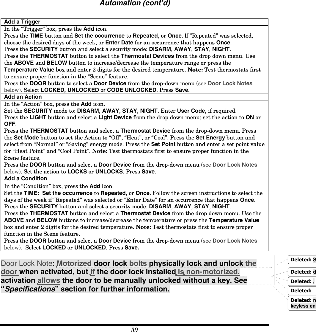
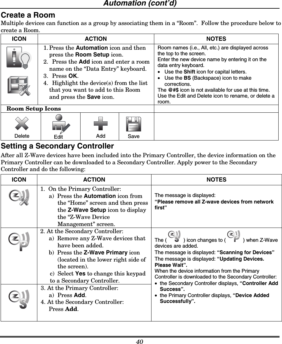
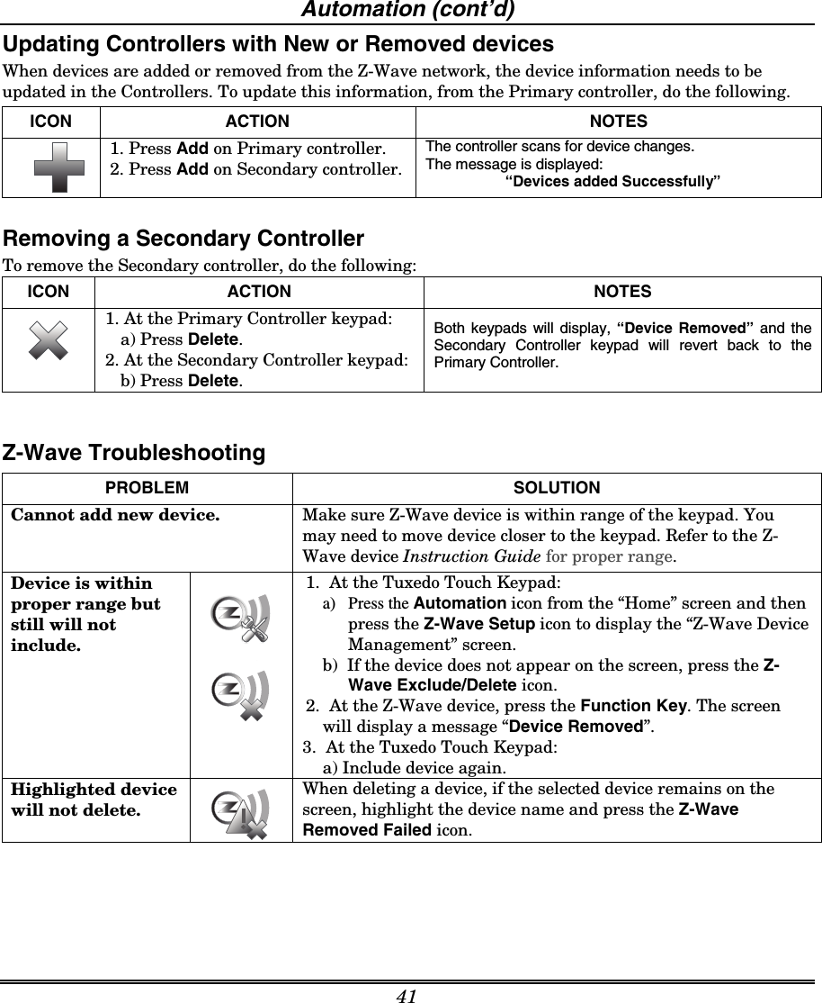
Ademco 8DL6280Z Tuxedo Touch Series User Manual 800 08221 A 6280i ii

Honeywell International Inc. Tuxedo Touch Series 800 08221 A 6280i ii

Users Manuals

    800-08221 10/24/11  Rev. A                                TTTTTTTTuuuuuuuuxxxxxxxxeeeeeeeeddddddddoooooooo        TTTTTTTToooooooouuuuuuuucccccccchhhhhhhh        SSSSSSSSeeeeeeeerrrrrrrriiiiiiiieeeeeeeessssssss        HHHHHHHHoooooooommmmmmmmeeeeeeee        AAAAAAAAuuuuuuuuttttttttoooooooommmmmmmmaaaaaaaattttttttiiiiiiiioooooooonnnnnnnn        SSSSSSSSyyyyyyyysssssssstttttttteeeeeeeemmmmmmmm         Installation and Setup Guide         PLEASE USE BOOKMARK ON THE LEFT OR GO TO PAGE 47 FOR AGENCY STATEMENTS
Table of Contents   iii  About the System............................................................................................................................5 Safe Mode ......................................................................................................................................... 5 Compatibility.................................................................................................................................... 5 Software Upgrades .......................................................................................................................... 6 Word List .......................................................................................................................................... 7 Mounting .......................................................................................................................................... 8 Wiring ............................................................................................................................................... 9 Specifications .................................................................................................................................. 10 Front Panel LEDs ........................................................................................................................... 11 Navigation Icons ............................................................................................................................. 11 Panel Fault Displays ...................................................................................................................... 13 Initial Setup .....................................................................................................................................14 Programming the Control Panel.................................................................................................... 14 Keypad Initialization...................................................................................................................... 14 Time and Date Setup...................................................................................................................... 15 Night Setup ..................................................................................................................................... 15 Web Server/Hosting ........................................................................................................................ 15 IP Setup ........................................................................................................................................... 15 Setup................................................................................................................................................17 Brightness and Volume Control..................................................................................................... 17 Display & Audio Setup ................................................................................................................... 17 Operating Modes............................................................................................................................. 17 Adjust the Screen Timeouts ........................................................................................................... 18 Clean Screen ................................................................................................................................... 18 Multi-Media......................................................................................................................................19 Picture Setup................................................................................................................................... 19 Camera Setup.................................................................................................................................. 20 Video (Audio) Setup ........................................................................................................................ 21 System Setup..................................................................................................................................22 CS Setup .......................................................................................................................................... 22 ECP Address Selection ................................................................................................................... 22 CS Options / Operating Modes....................................................................................................... 23 Operating Modes............................................................................................................................. 23 Screen Security ............................................................................................................................... 24 Code Authority ................................................................................................................................ 25 Device Events.................................................................................................................................. 25 Panel Configuration........................................................................................................................ 25 User System Setup.........................................................................................................................26
Table of Contents (cont’d)  iv How to Add a User.......................................................................................................................... 27 How to Add an Existing User to a Second Keypad....................................................................... 27 How to Delete a User...................................................................................................................... 27 Time/Date Setup ............................................................................................................................. 28 Setting Daylight Savings Time ...................................................................................................... 28 Setting Current Time and Date ..................................................................................................... 28 Advanced Setup .............................................................................................................................. 29 System Information ........................................................................................................................ 29 Keypad Reset................................................................................................................................... 29 Keypad Test..................................................................................................................................... 29 LED Test ......................................................................................................................................... 30 Calibration Test .............................................................................................................................. 31 NIGHT Setup Function .................................................................................................................. 31 Output Setup Function................................................................................................................... 32 Automation .....................................................................................................................................33 Including/Adding Z-Wave Devices .................................................................................................33 Include/Add a Light, Switch or Outlet Module ............................................................................. 33 Include a Door Lock ........................................................................................................................ 34 Include a Honeywell Thermostat................................................................................................... 34 Editing Z-Wave Device Names ...................................................................................................... 35 Edit a Device Module Name........................................................................................................... 35 Exclude/Delete Z-Wave Devices..................................................................................................... 35 Exclude a Light, Outlet, or Switch Module...................................................................................35 Exclude a Door Lock Device ........................................................................................................... 36 Exclude a Honeywell Thermostat..................................................................................................36 Exclude All Z-Wave Devices........................................................................................................... 37 Abort a Z-Wave Action.................................................................................................................... 37 Creating a Scene ............................................................................................................................. 38 Create a Room................................................................................................................................. 40 Setting a Secondary Controller...................................................................................................... 40 Updating Controllers with New or Removed devices................................................................... 41 Removing a Secondary Controller .................................................................................................41 Z-Wave Troubleshooting................................................................................................................. 41 Important Notes..............................................................................................................................43
  5 About the System This guide provides information to install and set-up Honeywell’s Tuxedo Touch Series Home Automation and Security System. The graphical touch-screen keypads are Advanced User Interface (AUI) devices, which combine home automation and home security.  Your system may consist of one or more of the following: • TUXS  Keypad (black/silver housing) • TUXW Keypad (white housing) • One or more other keypads for system control  • Various sensors for perimeter and interior burglary protection, plus a selected number of strategically placed smoke, carbon monoxide or combustion detectors  • Lighting/output devices.  Equipped with web-hosting capability and built-in Z-Wave technology, the Tuxedo Touch Keypad can be used to control the home environment, such as lights, appliances, thermostat, door locks and cameras via any web enabled device (PC, i-Pad, Smart Phone and Tablet). Note: To the installer, see the "Important Notes" in the Important Notes section of this guide. Safe Mode The keypad contains a Safe Mode of operation. In the rare event that the keypad cannot successfully communicate in its graphic mode with the control panel, the Safe Mode is a backup mode that ensures that you can communicate with your system. In this mode, the keypad operates much like a standard non-graphic keypad so that you can control your system until the problem is corrected. Note: Z-Wave and IP Cameras are not accessible via Safe Mode.   • DO NOT perform panel programming while in the Safe Mode. Performing panel programming while in the Safe Mode may cause the panel and keypad to become out of sync. •  DO NOT use several hardwired motion detectors in high traffic locations. The high quantity of signals received by the panel may cause the keypad to enter the Safe Mode. Compatibility The below listing identifies the alarm systems that the keypad can interface with, the maximum number of keypads that can be used with each system, and the minimum alarm panel software revision level for compatibility. Note: For SIA installations used with a VISTA-128BPTSIA Control, see the SIA CP-01 Quick Reference Chart located on MyWebTech, Document # 800-09699.    Alarm System Maximum Number of Keypads Minimum Software Revision Level VISTA-15P 2 3.0 VISTA-20P 2 3.0 VISTA-20P 4 5.0 VISTA-21IP  4 1.0 VISTA-128BP 3 3.2 VISTA-128FBP  3 3.0 VISTA-128FBP-9 3 4.1
About the System (cont’d)   6  Alarm System Maximum Number of Keypads Minimum Software Revision Level VISTA-250FBP-9  3 4.1 VISTA-250BP 3 2.4 VISTA-250FBP 1 3.0 VISTA-250FBP 3 2.0 VISTA-128BPE  3 4.4 VISTA-250BPE  3 4.4 VISTA-128BPEN  3 7.0 VISTA-128BPLT  3 6.0 VISTA-128FBPN  3 5.1 VISTA-128BPT  6 10.1 VISTA-250BPT  6 10.1 VISTA-128BPTSIA  6 10.1 FA148CP  2 3.0 FA168CPS  4 5.0 FA1660C  3 3 FA1660CT  6 10.1 FA1670C-9  3 4.1 FA1700C  3 3  Note: Keypad may only be used in the following UL/cUL installations: UL 365, UL609, UL 985, UL1023,  UL 1610, CAN/ULC-S303, CAN/ULC-S304, ULC-S545, ULC/ORD-C1023, and ANSI/SIA CP-01-2010.    •  On all panels except the residential panels, you may obtain the software revision level of the alarm panel by entering the program mode and then entering #92 on the keypad. This can be done from the Console Mode or a standard alpha keypad, if supplied. The second line of the keypad displays the software revision level (w/out the decimal point). •  The keypad sound suppression feature available in some commercial panels is not compatible with the Tuxedo Touch keypad. •  The ‘Voice Chime’ feature is a residential control feature only. Note: If using the maximum number of keypads, an additional auxiliary power supply may be needed.   Software Upgrades IMPORTANT: During the installation process, check the latest software version and if necessary go to MyWebTech to download the latest upgrade for your specific keypad model.
About the System (cont’d) 7 Word List          The Tuxedo Touch keypad can annunciate the words listed below. Please note that this listing does not increase the vocabulary available from your panel. You must use the listing in your alarm panel instructions for actual words that may be requested for annunciation.  AC-Loss Air Alarm Apartment Area Armed Attic Away Baby Back Bar Basement Bathroom Bed Bedroom Blower Boiler Building Bypassed Call Carbon-Monoxide Central Check Closed Computer Daughter's Den Detector Dining Disarmed Disarm-System-Now Door Down Downstairs Driveway Duct East Eight-Hundred Eight Eighteen Eighty Eleven Emergency Equipment Exit Factory Father's Fault Fence Fifteen Fifty Fire First Five-Hundred Five Floor Forty Four-Hundred Four Fourteen Foyer Front Garage Gas Glass Gun Hall Heat House Hundred Inside Instant Kitchen Laundry Left Library Light Living Loading Low-Battery Lower Machine Main Master Medical Mother's Motion Night Nine-Hundred Nine Nineteen Ninety North Not Now Off Office On One One-Hundred Open Outside Panic Patio Phone Police Pool Power Ready-to-Arm Rear Right Room Second Service Seven-Hundred Seven Seventeen Seventy Shed Shop Side Six-Hundred Six Sixteen Sixty Sliding Smoke Son's South Station Stay Storage Supervise Telco Temperature Ten Third Thirteen Thirty Three-Hundred Three Tool Twelve Twenty Two-Hundred Two Up Upper Upstairs Utility West Window Wing Yard Zero Zone
About the System (cont’d)   8 Mounting  This keypad is for indoor use only and should be mounted at a comfortable viewing level.  Avoid mounting in areas of high condensation such as bathrooms or in locations where bright light or sunlight shines directly on the screen.  The keypad can be mounted with or without the mounting plate. Use the center securing screw for European installations.  Mounting with mounting plate:  1.  Select a mounting location.  2.  Detach the mounting plate by sliding downward.   3.  Use the mounting plate to mark the location of the mounting holes on the mounting surface and check for level.   4.  Locate the mounting plate over the mounting surface such that the wire/cable access openings are aligned while passing the wires/cable through the case back.  **Go to “Wiring” (next page) and complete wiring**5. Secure the mounting plate to mounting surface using 4 screws (supplied).  6.  Slide keypad onto mounting plate. 6280-006-V0WALLSURFACEWALLMOUNTINGPLATE(OPTIONAL)MOUNTINGSCREWS (4)(TYP) Mounting without mounting plate:  1.  Select a mounting location.  2.  Detach the mounting plate by sliding downward and discard. 3.  Use the template (provided in the carton) to mark the location of the mounting screws and the cut-out for the keypad assembly on the mounting location. Check for level.  4.  Install 4 screws (supplied) in the mounting surface leaving screw heads 1/8” above the mounting surface.  5.  Locate the case back over the mounting surface such that the opening is aligned with the wire/cable access opening on the mounting surface while passing the wires/cable through the opening in the case back.  **Go to “Wiring” (next page) and complete wiring** 6.  Mount keypad by sliding onto the screw heads. 4 - 3/4"3 - 9/16"800-08831    5/11    Rev.ACUT-OUT LOCATIONDRILL 3/16" DIA. HOLES4 PLACESÊ800-00831uŠ6280 SERIES CASE BACK MOUNTING TEMPLATEDRILL 3/16" DIA. HOLE6280-016-V0MOUNTINGSCREWSINSTALLED1/8” ABOVESURFACETEMPLATEWALLSURFACE Mounting (European Installations) using a center securing screw: 1. Detach case front by removing the two bottom screws. Gently pull up using a screwdriver if necessary and pry apart. Lift off cover.  2. Mount the keypad in its final location, (see “Standard Mounting” or “Mounting without the mounting plate”) install center securing screw (supplied) and tighten to mounting surface. 3. Replace the case front and secure using the two bottom screws. 6280-015-V0INSTALL CENTERSECURING SCREWDETACH CASE FRONTBY REMOVING SCREWS (2)AND LIFT UPCASEFRONTCASEBACK
About the System (cont’d) 9 Wiring  Connect the Tuxedo Touch in parallel with keypads and other peripheral devices using the keypad data (ECP) bus.  • If the Tuxedo Touch is used as the primary system keypad, maximum wire run length is 150 feet. • If more than one keypad is wired to one run, then the maximum lengths must be divided by the number of keypads on the run.  (e.g., the maximum length is 75 feet if two keypads are wired on a #22 gauge run). Wire Gauge:      Length #22 gauge  150 feet #20 gauge  240 feet #18 gauge  350 feet #16 gauge  550 feet    Connect the wires to the keypad terminal block as shown below.   BLACKPOWER FROM SUPPLEMENTARYPOWER SUPPLY IF USEDRED BLACKGREENYELLOWCONTROLTERMINAL STRIPSUPPLEMENTARY+12 VDCPOWER SUPPLYP/N AD12612BLACK (GND)RED (+12VDC) GREEN( DATA  TOCONTROL)YELLOW(DATA FROMCONTROL)CONTROLTERMINAL STRIPAU X D ATAINDATAOUTAUXDATAINDATAOUTAUX AUXYG6280i-002-V0RJ45IP CONNECTION  IMPORTANT: When the keypad is powered from an auxiliary power supply, always apply power to the control panel first and then the keypad. Failure to observe this sequence results in improper operation of the keypad and may result in an ECP Error indication.  Supplementary external power supply must be Listed to UL 603 for UL installations, CAN/ULC-S318 for cUL installations, and capable of providing the required backup power.   The Keypad draws up to 310mA. If you power the keypad from your panel’s Aux Power output, check your panel’s Installation and Setup Guide and verify that this device and others do not exceed your panel's Aux Power output capability. If it does, a supplementary power supply is needed.
About the System (cont’d)   10 Specifications:  Mechanical Specifications:     Width: 8.23 inches (209.04mm)  Height: 5.59 inches (141.99mm) Depth:1.13 inches (28.70mm)        Electrical Specifications:     Backlight OFF, Sound OFF 12V, 140mA  Backlight ON, Sound OFF  12V, 205mA  Backlight ON, Sound ON  12V, 310mA Operating Environment: Humidity   93% RH, non- condensing Temperature: Operating                     14˚ F to 131˚ F / -10˚ C to 55˚ C  (UL tested 32˚-120˚F / 0 to 49˚C) Shipping / Storage  -40˚ F to 158˚ F / -40˚C to 70˚C    Compatible Devices Z-Wave devices may vary; follow the instructions in the Users Guide for your specific device when adding and deleting devices into the Z-Wave network.  Not all features are supported for off-the-shelf Z-Wave devices, refer to the table below for some of the compatible devices that have been tested: Door Locks  Schlage dead bolt door lock model # BE369CAM619   Schlage lever door lock model # FE599CAM619ACC Kwikset dead bolt door lock model #910TRLZW15SMTCP Kwikset lever door lock model # 912TNLTRLZW15SMTCP Yale door lock -  Thermostats Honeywell
About the System (cont’d) 11 Front Panel LEDs The Tuxedo Touch Keypad has three LEDs as follows:  6280-001-V0FLASHING – The system contains newmessage(s) for the User.OFF – No new messages.RESET BUTTONPress to unlock keypadON – System is armed.OFF – System is not armed.ARMED (RED) LEDREADY (GREEN) LEDON – System is disarmed and ready to arm.OFF – System is armed or disarmed but notready. If disarmed, faults or troubles are present.MESSAGE (YELLOW) LEDSD/SDHC CARD Slot *Note: If the EN50131 Display feature is enabled, the "Armed" and "Ready" status LEDs turn OFF after 30 seconds and the screen returns to the Home screen until a valid user code is entered.  Navigation Icons  To aid in the navigation through the Tuxedo Touch screens, a set of user-friendly icons has been provided.  The appearance and function are described below.  ICON ICON TITLE  FUNCTION  “Intro Video” Accesses the “Product Introduction Video”.  "Message"   Record and retrieve Voice Messages.   "Automation"   Accesses the Z-Wave setup, Scene setup, and Room setup screens.  "Security"   Accesses the "Security" screen.  “Home”  Returns you to the "Home" screen.   “Back”  Reverts to the last screen viewed.
About the System (cont’d)   12 ICON ICON TITLE  FUNCTION  “Panic” Displays Emergency functions (as programmed by the installer). See programming the Control Panel note. Note: This icon is displayed and active on all screens except while in the Clean Screen mode, during an LCD Display test in Diagnostics, and from the Video and Camera screen.  “Control Panel Message” This icon alerts the user to a Control Panel Message.  “Setup”  Accesses the Setup menus.  “Multi-Media”  Accesses the Message, Camera, Picture and Video feature.  “Video”  Allows user to play video files.  “Picture”   Allows user to display personal photos in a slide show format.  “Voice Status”  Allows user to hear system status.  “Minimize Home”  Minimizes the Home screen icons when viewing wallpaper displays.   “Maximize Home”  Maximizes the Home screen icons when viewing wallpaper displays.
About the System (cont’d) 13 Panel Fault Displays The “Security” screen displays an Icon(s) if a panel fault(s) occurs. The following Icons(s) may be shown as applicable to you system: ICON MEANING  AC Loss – The system is not receiving AC power.  Bell Failure – The system bell or siren has a problem. Note: This Icon is displayed when interfacing with residential panels only.  Expander Failure – The system has a failure in an expansion module.  Low Battery – The system battery, that powers the system during an AC power loss, is low.   LRR Supervision Failure – The Communication Device used to communicate with the central station has a supervision failure.   Max Attempts Exceeded – The system has exceeded the maximum attempts to communicate with the Central Station.   Pager Failure – The system cannot communicate with an assigned pager.  Telco-1 Cut – The system is not able to communicate with the central monitoring station over the primary phone line.  Telco-2 Cut – The system is not able to communicate with the central monitoring station over the secondary phone line.  Wireless Failure – The system is not able to communicate with its wireless devices.   Note:  If multiple faults exist, press the More Choices icon and then the Show Zones icon to view and scroll through the complete list of faults.
  14 Initial Setup Programming the Control Panel The keypad is not fully operational unless its address in the control panel has been enabled (set as an alpha console) AUI type device, and assigned to a partition (where applicable). For a list of alarm systems that the keypad can interface with, refer to the “Compatibility Table” in Section 1 of this document for the quantity of keypads that may be used and the required control panel software revision level. We recommend that you use either a standard alpha keypad or the keypad in Console Emulation Mode when programming the control panel. When in the Console Mode, the keypad emulates an alpha keypad and the programming of the panel is performed following the procedures provided in your panel’s Installation and Setup Guide. Note: When programming your control panel, if you change the zone types for your emergency zones you may disable the emergency buttons in the keypad. The emergency buttons in the keypad are active for zone types 06 (Silent Panic Button), and 07 (Panic Button), 08 (Medical Button), and 09 (Fire Button). Additionally, the Medical button is also compatible with a zone type 15 (24-Hour Medical) for panels that contain this zone type. On residential control panels (VISTA-20P or equivalent): Up to four keypads may be used (addresses 1, 2, 5 and 6). Addresses 1 and 2 (in field *189) are enabled by default. If the defaults have been changed, enable these addresses (in field *189) using an alpha-keypad and the Data Field Programming procedures located in the panel Installation and Setup Guide. On commercial control panels (VISTA-128BP, VISTA-128FBP, or equivalent): Addresses 1-2, and 3-30 may be used for controls under Rev. 10 supporting 3 AUI’s, see Important Note below. Addresses 1-30 may be used for controls Rev. 10 and higher supporting 6 AUI’s. These addresses in the control panel are normally not defaulted for AUI type devices. To enable the addresses you are using for keypads, use an alpha-keypad and follow the procedures for “Device Programming” in your control panel “Programming Guide.”   Important Note: If multiple keypads are being used, they must be set to addresses 1, 2, and X (where X equals any address from 3 through 30). Only one AUI type device may be assigned to an address from 3 through 30 on commercial control panels.  The Keypad should not be assigned as a Master Console. If the keypad is assigned as a Master Console, partitions must be controlled from the Partition screen or using the Console Emulation Mode. Keypad Initialization When initially powered, the screen displays the boot sequence and the "Set ECP Address" screen is displayed.  If the system is incorporating only one keypad, leave the address set to 1 and press Apply.  The boot-up process continues until completion. If there are to be additional keypads in the system, after enabling addresses in the control panel using an alpha-keypad, power-up each keypad one at a time, and set its address to one of the addresses you enabled in the control panel. Installer Note: The Tuxedo Touch Screen has been calibrated at the factory. Ignore the “CALIBRATE” button that appears on the “Options” screen after initial ECP setup. If the screen should require recalibration, the end user may do so via the “Keypad Test” screen. See the “Diagnostic Tests” section for instructions.
Initial Setup (cont’d)  15 Time and Date Setup If not already set from the control panel, set the current time and date. Refer to Time/Date Setup. Night Setup The Keypad is defaulted to arm the system in the STAY INSTANT mode when arming the system using the NIGHT icon.  Select the arming mode to be activated when the NIGHT icon is pressed on the “Arming” screen, refer to the “Night Setup” section.  Web Server/Hosting The Tuxedo Touch keypad offers web-hosting capability allowing you to access your Security and Home Automation System via any web enabled device. The Tuxedo Touch keypad IP Address is displayed on the “IP Setup” screen as well as on the “Home” screen. This IP Address is used on a standard web browser to control user functions such as, Security, Z-Wave operation and camera viewing. From your web enabled device, do the following: ACTION NOTES 1. At your Computer, i-Pad, Smart Phone or Tablet: a) Navigate to the Settings feature.  b) Turn ON the “Wi-Fi” setting and select the router to connect to. Enter a name and password, if required. c)  Open the browser and enter the IP Address displayed on the keypad into your browser.  •  If using a Smart Phone or Tablet browser, access to basic arming commands are available. • If using a Computer or i-Pad browser, full access to keypad options are available.  You can now control your Security System, local Z-Wave devices and view your local cameras from your browser.   IP Setup  Follow the steps below to control your local Z-Wave devices via your Computer, Tablet, Smart Phone or i-Pad.  Automatic IP Addresses In most cases, IP addresses are assigned automatically by your Internet Service Provider. The IP Address is displayed in the lower left-hand corner on the Tuxedo Touch Keypad “Home” screen.  To access “IP Setup”, from the “Home” screen, do the following:   ICON ACTION  NOTES         1.  At the Tuxedo Touch keypad: a)  Press the Setup icon.  b)  Press the IP Setup icon. The “IP Setup” screen displays the IP Address and Default Gateway Address of your router.  c) Press the Refresh button; the IP information will automatically update. This may take up to 60 seconds. 2. Press Apply; the keypad will save the information and reset.  Take note of the address; you will need to enter this address into your browser.       After proper setup, the IP Address is displayed on the “Home” page. UL  Web Server/Hosting is not Listed for use in UL installations. Remote Arming/Disarming/Programming is not to be used in UL Listed Installations.
Initial Setup (cont’d)   16  ICON ACTION  NOTES       To set up a User Account: 1. Press the Account Setup button. 2. Highlight the User ID number on the screen and enter a user name; press OK.3. Highlight the User ID number again and enter a user password; press OK. 4. Press the Save icon. The new user is displayed on the screen. 5. Press Apply. 6. To delete a user, highlight the User Name and press the Delete button.  Note: Account Setup allows you to add up to 5 users.  Use the Data Entry Keyboard to enter the required information.  • Use the Shift key for capital letters •  Use the BS (Backspace) key to make corrections. • Press OK  A pop-up window displays the message: Save the Change Select Yes to save the settings. Select No to cancel.   Fixed IP Addresses If the IP Address is not displayed in the lower left-hand corner on the Tuxedo Touch Keypad “Home” screen, you may require a fixed IP Address. Obtain the IP Address by contacting your Internet Service Provider and then do the following: ICON ACTION  NOTES    1.  At the Tuxedo Touch Keypad: a)  Press the Setup icon and then press the IP Setup icon; the “IP Setup” screen is displayed.  b) Press the button next to Obtain an IP address automatically to de-select it.  c) Enter the “IP Address” by pressing the first set of 3 zeros (“000”) on the screen, and enter the first three numbers of the IP address on the “Data Entry Keyboard”. Repeat this step until the complete address has been entered and press Apply. 2.  At your Computer, i-Pad, Smart Phone or Tablet Browser: a) Start your browser and enter your IP Address.    Use the Data Entry Keyboard to enter the required information.  • Use the Shift key for capital letters •  Use the BS (Backspace) key to make corrections. • Press OK     A pop-up window displays the message: Settings Changed! Remember new settings? Select Yes to save the settings. Select No to cancel.
 17  Setup You may access Brightness and Volume, Display & Audio Setup, System Setup and IP Setup from the "Setup" screen.  Brightness and Volume Control From the "Home" screen, access the "Setup" screen as follows: ICON ACTION  NOTES  1. From the Home screen, press the Setup icon. 2. Move the Brightness/Volume slide bar up or down to increase/decrease brightness/ volume. Yes saves the change. No discards the change. If changes are made, when you exit a “Settings Changed!” pop-up window is displayed asking “Remember New Settings?“  Display & Audio Setup You may access Operating Modes, Backlight Off After Time, To Homepage After Time, Auto Slideshow After Time, and Clean Screen from Display & Audio Setup. Operating Modes  Operating modes provides access to Chime Mode, Voice Mode, and Voice Chime. •  Chime Mode – Keypad chimes whenever a door or window is open. •  Voice Mode – Keypad voice annunciates whenever a change in system status occurs such as Armed, Disarmed, or Alarms. •  Voice Chime – The chime mode and voice mode are in effect. The chime beeps followed by voice annunciation. From the Home screen, press the “Setup” icon, and do the following: ICON ACTION  NOTES  1.  Press the Disp & Audio Setup icon.  2.  Enter your Authorized Code, if required.  If the Chime Mode and Voice Mode are both selected, the Voice Chime is automatically selected. When the keypad exits the “Operating Modes” screen, your selection is saved.  3.  Select Chime Mode or Voice Mode to turn the mode on or off.  4. Press the HOME or BACK icon after making your selection. It may take a few seconds for the Chime Mode to take effect.
User System Setup (cont’d)   18 Adjust the Screen Timeouts When the keypad is left idle, it automatically:  • Turns the “Backlight Off After” the selected backlight off time has expired (unless “Never” option is selected).   • returns to the “Home” screen after the selected “To Homepage After” time has expired (unless “Never” option is selected), and • if enabled, the “Auto Slideshow After Time” begins the slide show.  To select the desired screen timeouts, do the following: ICON ACTION  NOTES   1. From the "Home" screen, press the Setup icon.   2.  Press the Disp & Audio Setup icon. 3.  Enter your Authorized Code.   4. Press the desired selection from the drop-down list displaying the time period for each option. Yes saves the change.   No discards the change. If changes are made, when you exit a “Settings Changed!” pop-up window is displayed asking “Remember New Settings?“  Settings include: • Backlight Off After X time • Return To Homepage After X time • Auto Slideshow After X time. Notes • The “To Homepage After” Time option is only available if the EN50131 display option is not enabled by the installer. •  When in EN50131 mode, “Auto Slideshow After” is preset to “1” minute and can not be changed.  Clean Screen With the exception of normal cleaning, the keypad is maintenance free.   Press the “Display and Audio” icon, and do the following:  ICON ACTION  NOTES  1. Press the CLEAN SCREEN icon. A pop-up window displays "Touch Screen has been disabled so that you may wipe the screen clean. Please use a damp, soft cloth. DO NOT use any liquids, sprays, or ammonia-based cleaners. Press CONTINUE to disable touchscreen." *Panics cannot be initiated during this process* 2. Press Cancel to exit. When the "Continue" icon is pressed the message "Touch Screen Disabled for =30 Seconds" is displayed. During these 30 seconds the touch screen should be wiped clean of fingerprints using a mild soap solution and a soft cloth. When the counter reaches zero, the window automatically closes and the touch screen is active.  IMPORTANT:  Do not use an abrasive cleaning agent or abrasive cloth when cleaning the keypad or damage to the touch screen may occur.    The Emergency screen cannot be accessed while running in the clean screen mode.
 19 Multi-Media This feature allows you to access voice messages, play video files, display personal photos in a slide show format, and view up-to four cameras at one time from your keypad. UL    Multi-Media functionality is supplementary only and has not been evaluated by UL.  Picture Setup The Picture feature allows the user to display up to 1000 personal photos on the touch-screen and can be accessed from the Home screen by pressing the Picture icon, or access this feature as follows: ICON ACTION  NOTES       1. Insert your personal media (SD/SDHC) card (with stored picture files) first. 2. Press the Multi-Media icon and then press the Picture icon.  3.  Select the type of viewing transition desired (Standard, Horizontal, Vertical or Fade Out) by pressing the Transition arrow.   4. Press the Slide Delay arrow to select the time interval that you want to allow between each photo being viewed. Choose from (5, 10, 15, or 20 seconds).  To set a picture as wallpaper: 1. Use the slide bar to highlight the file you want to be displayed on the keypad screen.  2. Press the Set Wallpaper icon; view your selection from the “Home” screen. Photo files can be viewed from the (SD/SDHC) Card.  Formats supported are .bmp or .jpg files. NOTE:  •  To exit slide show at any time and resume keypad operation, press anywhere on the screen. •  The first image is displayed and a list of stored images appears on the screen.  •  When an image is loading, no other Picture Setup function can be performed (play, previous, next, add or set wallpaper). Press the TOP button to move up one level in the directory. Press the OPEN button to view larger images and/or open directories, select from the list of stored images. Press the CLEAR ALL button to clear all pictures from the current slide show rotation. NOTE: When viewing wallpaper displays, the Home screen icons can be minimized by touching the “Minimize Home” icon.   Picture Icons  Play Image  Previous Image  Next Image  Add Image  Minimize Home        Maximize Home  Deleted: is
Multi-Media (cont’d)   20 Camera Setup The Camera feature allows you to view up-to four cameras at one time. Cameras should be in their final location and turned on before they are added to the system. To add a camera, do the following: SCREEN ACTION  NOTES    1. Connect an RJ45 cable to the back of the Tuxedo Touch Keypad and connect the other end of the RJ45 cable to your Ethernet on your existing “powered-up” router.  2. Connect an RJ45 cable to the back of your camera (LAN) and connect the opposite end to the Ethernet on your router. 3. Apply power to the Camera. Wait a few seconds for initial power-up of camera. 4. Press the Multi-Media and Camera icons or press the Camera icon from the “Home” screen and then press the Camera Setup icon. The “Camera List” screen is displayed. Initial camera setup cannot be performed over a wireless connection.  Use the Data Entry Keyboard to enter the required information.  • Use the Shift key for capital letters • Use the BS (Backspace) key to make corrections. • Press OK      5. Press the Scan icon to locate the camera. Once located, highlight the camera address, and press the Edit icon and go to Step 7.  6. If the camera information is not automatically obtained, press the Add icon to manually enter information on the “Add Camera” screen. 7. To edit camera information, highlight the camera and press the Edit icon; the “Camera Configuration” screen is displayed.     8. When all cameras have been added, press the Wireless Settings icon and on the “Wireless Settings” screen enter the wireless information from your router.  9. Press Apply to All to set cameras to wireless operation. If camera does not have wireless capability, leave camera connected to router. Enter the appropriate information (Name, User, RTSP Path, Resolution, Frame Rate, Address, Password, RTSP Port, HTTP Port) if known. Enter the appropriate wireless information SSID, Network Type, Channel No., Security System and Shared Key, if applicable. Security System information for WEP enter Authentication Type, WEP Encryption, Pass Phrase, and WEP Key. For WPA PSK TKIP, WPA PSK, AES, and WPA2 PSK AES, enter the Shared Key using the Data Entry keyboard and press OK.  A pop-up window displays “cam (name) wireless set OK”, if successful. Or, “cam (name) wireless set Failed”.  The RJ45 cable can now be removed from the wireless cameras and (once power has been recycled to the camera) you can view wirelessly via the Tuxedo Touch Keypad. Setup Icons Camera Icons   Play    Scan   Add  Delete Clear Clear  Edit  Refresh  Stop  Auto Pan QuadView  Full View   Pan/Tilt  Back Note: To use the Pan/Tilt feature in Quad View, select the camera name from the camera list and then press Pan/Tilt. UL  Camera functionality is supplementary only and has not been evaluated by UL.
Multi-Media (cont’d)  21 Video (Audio) Setup To access the Video (Audio) feature, from the “Home” screen do the following: ICON ACTION  NOTES   1.  Insert your personal media (SD/SDHC) card (with stored video files) first. 2. Press Multi-Media and then press the  Video icon. 3. Highlight a video file from the list and press Play to start the selected video file. 4. Press the Repeat icon to continually replay the selected video.   5. Deselect the Repeat icon to automatically play the complete list of video files starting with the first video and ending with the last. Note: A Video Converter is required to convert videos for proper playback on the Tuxedo Touch Keypad. Use an Internet search engine to locate and download a Video Converter, then follow the steps in the Video Converter Instructions (provided in the carton). Note: Maximum video resolution should not exceed 400 x 240.  Note: If the video file causes the keypad to lock, use a small object (such as a paper clip) to press the reset button located in the lower right-hand side of the keypad to reset the keypad. •  Use the slide bar to scroll through the video list. •  If desired, press the Full View icon to view video in full screen.     Video Icons   Play  Pause  Full View  Repeat Touch the appropriate icon to Play, Pause, view a Full View or Repeat the video.
 22 System Setup  From System Setup, you may access CS Setup, User Setup, Time & Date, and Advanced Setup.   CS Setup You may access ECP Address, CS Options/Operating Modes, Screen Security, Device Events, Code Authority and Panel Configuration from the CS Setup screen. From the “Home” screen, press the Setup and System Setup icon and perform the following: ICON   ACTION  NOTES   1. From the System Setup screen, press the CS Setup icon.   2. Enter your Authorized Code, if required.  3. Press the ECP Address icon. If the top of the screen is displaying “ECP Error”, the ECP address in the keypad is not valid for the panel that it is connected to. In this case, change the ECP to the keypad default code of “4140” to advance to the next screen. Note: Default code “4140” is the Tuxedo Touch default installer code before connecting to a control panel.  Once connected to a control panel, use that panel’s installer code.  ECP Address Selection After enabling addresses in the control panel using an alpha-keypad, power-up each keypad one at a time, and set its address to one of the addresses you enabled in the control panel.  Otherwise, access the Central Station screen then follow this procedure to change the address on the unit. To change the address, perform the following: ICON ACTION  NOTES 123  1. Press the ECP Address icon. 2. Select the ECP address for this keypad using the Up/Dn arrows.  3.  The available ECP addresses are: 1-2, 5-6  for residential controls 1-2, 3-30      for commercial controls under                  Rev. 10 supports 3 AUIs. See     Important Note below. 1-30             for commercial controls Rev. 10   and higher supports 6 AUIs. IMPORTANT: If multiple keypads are being used, they must be set to addresses 1, 2, and X (where X equals any address from 3 through 30). Only one AUI type device may be assigned to an address from 3 through 30 on commercial control panels.  When the keypad cannot communicate with the alarm panel, the message “ECP Error” is displayed, check the following: •  Verify that the AUI type device is enabled in the control panel, and that the ECP address in the keypad matches the address enabled in the control panel.  Use a different address for each device.   •   If powering the keypad from a power supply, make sure you have a common ground installed (wiring between Power Supply "gnd" and panel "Aux. power neg"). NOTE: When the ECP address is changed, and Apply is selected, the keypad resets.  The keypad should not be assigned as a Master Console. If the keypad is assigned as a Master Console, partitions must be controlled from the Partition screen or using the Console Emulation Mode.
System Setup (cont’d)  23 CS Options / Operating Modes The "CS Options" menu allows you to enable Display Lighting and the EN50131 Display feature.  The "Operating Modes" menu allows you to access "Normal Mode", "Safe Mode" and "Automation/Demo Mode". Compliance Feature (EN50131) The EN50131 Display compliance feature is a European Standard designed to prevent unauthorized users from knowing the status of the Security System. When the EN50131 Display is turned ON: • The keypad returns to the "Home" screen after 30 seconds; "Armed" and "Ready" LEDs turn OFF.  • The "To Homepage After" time setting changes to 30 seconds and the time is non-selectable.  • The “Auto Slideshow After” is preset to “1” minute and can not be changed. • The Security, Message and Lighting screen does not display system status until an authorized user code is entered. • The "Setup" menu does not display system status until an authorized user code is entered.  From the Home screen, press the Setup and System Setup icon.  Operating Modes Safe Mode The Safe Mode may be automatically entered by the program on a communication failure or may be entered manually on command.  Automatic Entry In the rare event that the keypad cannot successfully communicate in its graphic mode with the control panel, the screen presents you with a message of “Problems detected. Start Keypad in Safe Mode?” and requests a “Yes” or “No” response. If you answer with “Yes”, the keypad goes into the Safe Mode. If you answer with “No”, the keypad tries to communicate with the panel again. After 3 consecutive times of receiving no response, the keypad enters the Safe Mode automatically. Manual Entry Note: ONLY enter the Safe Mode from the Normal Mode. Entering the Safe Mode from the Automation/Demo Mode may result in incorrect display of the Emergency Function keys. ICON ACTION  NOTES ! SAFE MODE !1. Select Safe Mode and then press Apply.   2. Press OK.   3. To exit, touch the safe mode bar and touch Yes to return to Normal Mode.  The “Warning” message "Keypad will reset to activate changes" is displayed. The keypad resets and restarts in the Safe Mode.  ICON ACTION  NOTES   1. Press the CS Options icon. 2. Enter your Authorized Code, if required.    3. Select “Lighting" or "EN50131 Display" to turn the option on or off. 4. Select "Normal Mode" or "Safe Mode" to turn the option on or off.  Apply accepts all changes.   Note: The Automation/Demo Mode option allows the automation and multi-media features to operate in a non-security mode.  When this option is selected, the keypad does not communicate with the control panel and any user can select Advanced Setup screens.
System Setup (cont’d)   24 Operating in the Safe Mode While in the Safe Mode, the Home screen displays the Security Icon, Panic Icon, and Message Icon. A message at the bottom of the screen is displaying: !SAFE MODE! This is a limited mode of operation. While in this mode: •  You can use the Security icon to access the Console Emulation Mode of operation to try to clear your faults, disarm the system, or enter additional Alpha Keypad commands specified in your panel User and Installation Guides. You can perform almost all functions that you can perform from a standard non-graphic alpha keypad. •  You can press the “Panic” icon and generate Emergency Messages as defined in the panel's home partition for this keypad. •  The Armed and Ready LEDs on the front of the keypad indicates the keypad’s home partition status.  •  The Chime mode functions in the Safe Mode: however, you do not have Voice, Voice Chime, or Message capability.  Note: Z-Wave Scenes do not function in Safe Mode. WARNING: The Slide Show feature does not start automatically in Safe Mode. Screen Security The Screen Security icon displays a list of authority levels and the user level that has been given access to them.  To view and/or edit Screen Security, do the following: ICON ACTION  NOTES  1. From the System Setup screen, press the CS Setup icon. 2. Enter your Authorized Code. 3. Press the Screen Security icon.    4.  If authority levels are correct, press BACK or Home to exit the menu. 5.  If changes are necessary, select the line to be changed and the level of user to have access; then select OK or Cancel. Note:  The Screen Security screen contains a heading of Advanced Setup, Central Station Setup, Disp. & Audio Setup, Event Logs, Lighting, Message, Security, or Time/Date highlighting the line was selected for change. The Screen Security screen is re-displayed listing any changes.  Note: The User Levels listed on this screen match the User Levels in commercial panels. See the following chart for corresponding User Levels in Residential Panels.  Residential Panels and Screen Security Access Level Chosen in Keypad Screen Security Authority Level in Panel Matching Authority Level in Keypad Installer Master Manager Operator A Operator B Operator C System Master  Master  No  Yes Yes Yes Yes  Yes Partition Master  Master  No  Yes Yes Yes Yes  Yes Standard User  Normal  No No No Yes Yes  Yes Arm Only  N/A  No No No No No  No Guest  Guest  No No No No Yes  Yes Duress  N/A  No No No No No  No
System Setup (cont’d)  25 Code Authority The Code Authority screen displays User Names and Partition Authority Level for the User Code.  To view the Code Authority level, do the following: ICON ACTION  NOTES  1.  Press the Code Authority icon.   2.  Enter the 4-digit User Code for the user that you want to obtain Authority Level information about.  3.  Press BACK. Note: If the User Code entered is not active in the system, a “NOT VALID” message will be displayed.  Device Events Your system has the ability to record events in a history log. Each event is recorded with the time and date of its occurrence. The control panel must be programmed to record various system events in installer programming mode. To view the Device Events, perform the following: ICON ACTION  NOTES  1.  Press the Device Events icon.  A list of events is displayed. To view a record of events in a history log, press the up/down arrow to scroll.  Panel Configuration The Panel Configuration screen displays the configuration of the panel. To view the panel configuration, do the following: SCREEN ACTION  NOTES   1. Press the Panel Configuration icon.   2. If correct, press Back to return to “System Setup” screen.  A "Panel Configuration" screen is displayed providing details of your system. Delete clears the configuration from the keypad and reloads the panel configuration into the keypad from the panel.  After you press Delete, a confirmation screen is displayed.
 26 User System Setup User Setup provides access to Add a User, Delete a User, and Edit a User. User Code Setup Each user must be assigned a name with a corresponding 4-digit user code in order to gain access to various features and functions. The keypad can hold the identity for 10 Users in its memory. If additional Users are needed, define the additional Users using the Console Emulation Mode. Users for the system are programmed in a central user setup location that provides the specific questions for authorization levels assigned to different users.  You may want these users to be the same, but there are situations in which you may want a user to have limited capabilities. These capabilities are defined by the Authority Level assigned to each user. Authority Levels  Authority levels define the system functions a particular user can perform. Depending on the authority assigned to you, there are certain system functions you may be prohibited from performing. The following information describes the authority levels available in the keypad and provides the equivalent authority level name found in your alarm system manuals. The authority levels available in the keypad are as follows: Equivalent System Name Keypad Authority Level Functions  Residential Systems  Commercial Systems Installer  Can perform all security functions except can only disarm if code was used to arm, can change Master Code, cannot change other user codes, can access the Central Station Screen options Note: This authority level cannot be assigned using the keypad. Installer Installer Master  Can perform all security functions, add/delete users in assigned partition, program scheduled events, and change partition master code. Partition Master  Level 1 Master Normal  Perform security functions (arm, disarm)  Standard User  Level 3  Operator A Guest  Can arm the system in assigned partitions, but cannot disarm the system unless the system was armed with this code. Note: Do not assign this level if Quick Arm is enabled in the system. Guest  Level 4  Operator B No Access  Used to restrict access to a partition.  N/A  N/A Note: The authorized code for deleting, adding, and editing users is dependent upon the alarm panel you are interfacing with. Check your alarm panel Installation and Setup Guide to determine who can delete, add, and edit users. Access User Setup as follows: ICON   ACTION  NOTES  1.  From the "Home" screen, press Setup and the System Setup icon.      2.  Press the USER Setup icon.
User System Setup (cont’d)    27 How to Add a User Add a user, from the "Home" screen, do the following: ICON ACTION  NOTES       1.  Press the Setup icon.   2.  Press the System Setup icon.   3.  Press the USER SETUP icon. 4.  Press the ADD USER icon and enter your Authorized Code.   5.  Press the box next to Enter User Name.   6.  Type in the user name (6 characters max.; no spaces between characters) and press the OK icon. 7. Press the box next to User Number and enter an available (3-digit) user number; press the OK icon.  8. Press the box next to Enter User Code, enter the 4-digit User Code for this user and press the OK icon.  9. Press the box next to RF Button Zone (if used); enter the 3-digit RF Button Zone for this user.   10.  Press the Save icon.   • Use the Shift key for capital letters • Use the BS (Backspace) key to make corrections. • The @#$ key is not available for use at this time. These characters cannot be saved to the control panel.     Select the partitions, access level, and enter an available user number for this user. Available user numbers: For Residential enter a number from 002-49. For Commercial enter a number from 002-250.   If assigning this user to wireless key, enter one of the zone numbers of the keyfob (the wireless key must be programmed first before it can be assigned to a user).    How to Add an Existing User to a Second Keypad After adding a user to the first keypad, the same user can be added to a second keypad. From the second keypad go to “User Setup” and enter the same user name and same user code (refer to “How to Add a User” above). The second keypad will automatically update the user information. Press Save. How to Delete a User Delete a User as follows: ICON ACTION  NOTES  1.  Select the User you want to delete. 2.  Press the DELETE USER icon.   3.  Enter your Authorized Code.   4.  Press the appropriate icon.   Three selections are available: add a user, edit a user, or delete a user. The Confirm Delete screen is displayed. How to Edit a User Note: You cannot edit a User name or User number. To modify a User name or User number, you must delete the User and re-enter the User. Edit a User as follows: ICON ACTION  NOTES  1. Press the EDIT USER icon.   2. Enter your Authorized Code.   3. Select the options needed for this user and press Save.   Three selections are available: add a user, edit a user, or delete a user.
User System Setup (Cont’d)  28  Time/Date Setup You can set the time and date from the Set Time & Date screen.   When the time is set it is stored in the keypad and sent to the control panel when you press Apply and answer Yes to the following prompt. Additionally, when using the keypad with a residential panel, the panel downloads its time into the keypad once an hour after the clock is set. If the Get Time icon is pressed, the keypad downloads the time and date from the control panel and exits the Set Time & Date screen. Note:  This icon   appears with residential panels and may not appear with all commercial panels. Setting Daylight Savings Time  To set the daylight savings time, from the "Home" screen do the following: ICON ACTION  NOTES  1.  Press Setup and the System Setup icon.   2. Press the Time/Date Setup icon and enter your Authorized Code. 3. Press the DST icon if you want daylight savings time to affect your system clock.   4. Set the “Start DST” time and then the “End DST” time by pressing the Month, Weekend and Hour that you want DST to start. 5. APPLY saves the settings.  If DST On (Daylight Savings Time) is selected, the keypad adjusts for Daylight Savings time at the month, week and time chosen.   Make sure "DST" On is checked to enable this feature.  Setting Current Time and Date To set the current time, do the following: ICON ACTION  NOTES     1.  Press the Month "arrow", and select the current month.   2. Press the Year that is being displayed and enter the current year. 3.  Press the Hour that is being displayed and enter the current hour. 4. Press the Minutes that is being displayed and enter the current minute. After each selection the window closes automatically and the selection is displayed. Each depression switches the AM/PM display. The selected date is highlighted on the screen. Select if you want a 12-hour or 24-hour format for your time display by pressing the circle to the left of the 12 Hour display.
User System Setup (cont’d)    29 ICON ACTION  NOTES  5. Select AM or PM by pressing on the AM or PM display on the screen. 6. Select the day of the month by pressing the proper day.  7. Press Apply.   Yes saves the time changes in your security system. No saves the changes to the keypad only. A confirmation screen is displayed. Each press switches the AM/PM display. The selected date is highlighted on the screen.   Note: A Yes response is recommended.   Advanced Setup The Advanced Setup screen allows access to Software Version, Keypad Reset, Keypad Test, Night Setup and Output Setup menus. System Information  To view the latest software version installed on your system, do the following: ICON ACTION  NOTES  1.  From the "Home" screen, press Setup and the System Setup icon.   2. Press the Advanced Setup icon.  3. Enter your Authorized Code.  The  “Software Version” is displayed in the lower right corner of the screen.  Keypad Reset To access Keypad Reset do the following: ICON ACTION  NOTES  1.  From the "Home" screen, press Setup and the System Setup icon.   2. Press the Advanced Setup icon.  3. Enter your Authorized Code.   4. Press the Keypad Reset icon.  If the keypad requires resetting, press OK and the keypad resets. If Cancel is selected, keypad is not reset. Keypad Test A series of diagnostic tests are provided that allows verification of correct operation of the keypad and its connections to the security system.  There are a total of four diagnostic tests; LCD Display Test, Audio Test, LED Test, and Calibration Test.  Performing Diagnostic Tests Select any diagnostic test from the Diagnostics screen by pressing its associated Test icon.  All or any individual test may be run when you access the Diagnostics screen; however, each test must be performed one at a time.  At any time when a test is not being performed, you can press: • back to return to the previous screen, or  • home to return to your home page.  Once the Diagnostics screen is exited, subsequent entry to this screen displays all test options as "Not Performed."
User System Setup (Cont’d)  30  LCD Display Test Perform the LCD Display Test as follows: ICON ACTION  NOTES  1.  Press the Advanced Setup icon.   2.  If applicable, enter your Authorized Code.   The Emergency screen cannot be accessed while running the LCD Display Test.   3. Press the Keypad Test icon.         4. Press the LCD Display Test icon; a series of screens appear.  After each type of display, you are asked if the display was proper.  If the response to all questions is yes, the LCD Display Test message area of the Diagnostics screen displays “Passed”.  Audio Test Perform the Audio Test as follows: ICON ACTION  NOTES  1. Press the Audio Test icon; "Testing.." is displayed while beeps sound from the speaker.  At the conclusion of the test, a pop-up "Confirmation Window" is displayed with the question "Did you hear Beeping?"  When you press Yes, "Passed" is displayed in the test status column on the "Diagnostics" screen. When you press No, "Failed" is displayed in the test status column on the "Diagnostics" screen.  LED Test Perform the LED Test as follows: ICON ACTION    1. Press the LED Test icon; "Testing.." is displayed while the 3 LEDs light sequentially, top to bottom (red, green, yellow), 5 times.    At the conclusion of the test, a pop-up "Confirmation Window" is displayed with the question "Did you see chasing LED pattern?"  If you press Yes, "Passed" is displayed in the test status column on the "Diagnostics" screen. If you press No, "Failed" is displayed in the test status column on the "Diagnostics" screen.
User System Setup (cont’d)    31 Calibration Test If the Touch Screen requires recalibration, do the following: NIGHT Setup Function The NIGHT function can be set to arm the system in one of five arming modes: • Away - Arms all zones with entry delay. • Stay - Arms perimeter zones with entry delay. • Instant - Arms perimeter zones without entry delay.  • Night (Residential Panels Only) – Arms all perimeter zones plus all zones listed in Zone List 5. • Maximum - Arms all zones without entry delay. Not to be used for ANSI/SIA CP-01 installations. To set the NIGHT function, do the following: ICON ACTION  NOTES  1. Press the System Setup and Advanced Setup icon. 2. Enter your Authorized Code, if required.   3. Press the Night Setup icon.   4.  Select the arming mode to be activated when NIGHT is selected on the "Arming" screen.  Apply accepts the setting. Back cancels your selection.    ICON ACTION    1. Select the Calibration icon and using a stylus, follow the screen directions by pressing a series of crosshairs (+) and boxes (❏❏❏❏) on the screen until done.   2. If the test was successful, press OK. The screen returns to the Keypad Test screen. 3. If the test was unsuccessful, choose to Retry, Ignore or Exit. If the Calibration test was successful, a confirmation screen appears stating: “Congratulations Calibration Successful!!!” If the test was unsuccessful, an error message appears indicating the Part of the screen that failed and stating: “Calibration failure, do you want to retry?”
User System Setup (Cont’d)  32 Output Setup Function The Output Setup function allows you to disable Output selection. There are a maximum of 18 outputs that can be enabled or disabled.  To set the Output Setup function, do the following: ICON ACTION  NOTES   1. Press the System Setup and Advanced Setup icon.   2. Enter your Authorized Code, if required. 3. Press the Output Setup icon. 4. Press the Output Disable icon to disable the selection.  5. Press the Output Enable icon to enable the Output selection. This is a local setting for the graphic keypad. If user has the maximum number of keypads on the system, and wants to disable the same output for all, each keypad needs to be set individually.  Apply accepts the setting.   Back cancels your selection.  Output Setup Icons  Output Disable  Output Enable  Apply Back
 33 Automation Before a device will work in the home control network, it must be “Included” (added) into the network. Follow the instructions below to Include a Z-Wave enabled device into a home control network using the Tuxedo Touch keypad. NOTE: Z-Wave applications have not been evaluated by UL. WARNING: Automation is intended for lifestyle convenience. Do not use automation for life safety and property protection. UL  Automation functionality is supplementary only and has not been evaluated by UL.   Including/Adding Z-Wave Devices Before including Z-Wave devices, each device must be installed according to the manufacturers’ instructions and in their final location and turned on.  UL  Access control functionality has not been evaluated by UL and may not be used in UL Listedapplications.  Include/Add a Light, Switch or Outlet Module To include a Z-Wave Light, Switch or Outlet module, do the following: ICON ACTION  NOTES   1. At the Tuxedo Touch Keypad:  a) Press the Automation icon from the “Home” screen and then press the  Z-Wave Setup icon to display the  “Z-Wave Device Management” screen.  b) Press the Z-Wave Include/Add icon.    2. At the device Module: a)  Press the Function Key on the device. Note: Z-Wave light modules may vary; follow the instructions in the User Guide for your specific device to include properly. • If a dimmer module was added, an On/Off button and a slide bar (to control the dimmer) are displayed. • If an on/off light, appliance, switch or outlet module was added, an On/Off button (to control the device) is displayed. The keypad displays a series of messages: “Start add device.  Please press function key on device” “Adding Controller Unit” “Adding Slave Unit” “Device added successfully” Z-Wave Device Management Icons   Include/Add   Exclude/Delete   Abort  Remove Failed  Edit  Reset Default   Router   Security   Link
Automation (cont’d)   34 Include a Door Lock  Assemble the Z-Wave door lock (if required); install batteries and connect necessary cables (refer to the Door Lock’s Instruction Guide). Enroll the door lock adjacent to the keypad and mount within the proper Z-Wave range. NOTE: Program the user code in the control panel prior to programming that user code into the door lock.  User Codes must be 4-digits. Include a door lock device as follows: ICON ACTION  NOTES    1. At the Tuxedo Touch Keypad: a) Press the Automation icon from the “Home” screen and then press the  Z-Wave Setup icon to display the “Z-Wave Device Management” screen.b) Press the Z-Wave Include/Add icon. 2. At the door lock: a) Program the selected user code from the panel; refer to Door Lock User Guide.  Note: Door lock devices may vary; follow the instructions in the Users Guide for your specific door lock to include properly and to program a new user code. The keypad displays a series of messages: “Please press function key on device” “Adding to Security Network” “Device added successfully” Note: If software is upgraded on the Tuxedo Touch keypad, re-included the door lock and re-set the user code in the door lock. Follow the screen instructions to complete the inclusion. Include a Honeywell Thermostat Install a Honeywell Thermostat according to the manufactures instructions.  Device should be mounted in the final location and tested before adding it to the system.   To include a Honeywell Thermostat into a Z-Wave network, do the following: ICON ACTION  NOTES        1. At the Tuxedo Touch Keypad: a) Press the Automation icon from the “Home” screen and then press the  Z-Wave Setup icon to display the  “Z-Wave Device Management” screen.b) Press the Z-Wave Include/Add icon. 2. At the Z-Wave thermostat: a) Select Thermostat; set the Time and Date. b) Follow the instructions in the thermostat Installation Guide for  “Z-Wave inclusion”. c)  To complete inclusion, press Done. d) Press Exit on the thermostat to return to normal operation. 3. At the Tuxedo Touch Keypad: a) To verify activation, press the Back icon and wait 30 seconds. Note: If installing another brand of thermostat, follow the instructions in the Users Guide for that specific thermostat to include properly. Some thermostats do not update temperature status automatically (i.e., Wayne Dalton). IMPORTANT: Honeywell is not responsible for property damages due to improper setting of the thermostat modes.   The keypad displays a series of messages: “Please press function key on device” “Adding Controller Unit” “Adding Slave Unit” “Device added successfully” Follow the screen instructions to complete the inclusion.  Press the Refresh icon; the device is displayed.
Automation (cont’d)   35 Editing Z-Wave Device Names Edit a Device Module Name To edit a device name, do the following:  Exclude/Delete Z-Wave Devices Exclude a Light, Outlet, or Switch Module To exclude a device from the Z-Wave network, do the following: ICON ACTION  NOTES   1.  At the Tuxedo Touch Keypad: a)  Press the Automation icon from the “Home” screen and then press the  Z-Wave Setup icon to display the  “Z-Wave Device Management” screen. b)  Highlight the device to exclude and press the Z-Wave Exclude/Delete icon. 2.  At the device module: a)  Press the Function Key to exclude the device from the keypad. Z-Wave Exclude/Delete -clears the node from the keypad and resets device to the default setting.   Notes:  •  If the device is not excluded, refer to the “Z-Wave Troubleshooting” section. •  To remove a defective device, refer to the Z-Wave Troubleshooting section.  ICON ACTION  NOTES    1. At the Tuxedo Touch Keypad: a)  Press the Automation icon from the “Home” screen and press the Z-Wave Setup icon to display the “Z-Wave Device Management” screen. b)  Highlight the device name and press the Z-Wave Edit icon. c)  On the “Data Entry” keyboard, press Clear and enter a new name. d)  Press OK. Enter the new device name by entering it on the data entry keyboard.   • Use the Shift icon for capital letters. • Use the BS (Backspace) icon to make corrections. The @#$ icon is not available for use at this time.
Automation (cont’d)   36 Exclude a Door Lock Device To exclude a door lock module from the Z-Wave network, do the following: ICON ACTION  NOTES   1.  At the Tuxedo Touch Keypad: a)  Press the Automation icon from the “Home” screen and then press the  Z-Wave Setup icon to display the  “Z-Wave Device Management” screen. b)  Highlight the device to exclude and press the Z-Wave Exclude/Delete icon. 2.  At the door lock: a)  Press the Function Key to exclude the device from the keypad. Z-Wave Exclude/Delete-clears the node from the keypad and resets device to the default setting. Notes:  • If the device is not excluded, refer to the “Z-Wave Troubleshooting” section. • When excluding the door lock, the user code associated with the door lock will remain in the system. If needed refer to the panel Installation Instructions on how to exclude this user code. • To remove a defective device, refer to the “Z-Wave Troubleshooting” section.   Exclude a Honeywell Thermostat To exclude a Honeywell Thermostat from the Z-Wave network, do the following: ICON ACTION  NOTES  1. At the Tuxedo Touch Keypad: a)  Press the Automation icon from the “Home” screen and then press the  Z-Wave Setup icon to display the  “Z-Wave Device Management” screen. b)  Highlight the thermostat and press the Z-Wave Exclude/Delete icon. Note: Honeywell is not responsible for property damages due to improper setting of the thermostat modes. Z-Wave Exclude/Delete -clears the node from the keypad and resets device to the default setting.   2. At the thermostat:  a)  Follow the instructions in the thermostat Installation Guide under “Installer setup” to “Remove a Z-Wave Network Connection”. b)  Once the exclusion process is complete, press Done and the thermostat is excluded. Notes:  •  If the device is not excluded, refer to the “Z-Wave Troubleshooting” section. •  To remove a defective device, refer to the “Z-Wave Troubleshooting” section.
Automation (cont’d)   37 Exclude All Z-Wave Devices ICON ACTION  NOTES   1.  At the Tuxedo Touch Keypad: a)  Press the Automation icon from the “Home” screen and then press the Z-Wave Setup icon to display the “Z-Wave Device Management” screen. b)  Press the Z-Wave Reset icon to delete all devices from the controller. c)  Press the Continue or Cancel button. The message is displayed: WARNING!! This Z-WAVE controller is about to be factory defaulted and will loose all devices in the enrolled list.   All Z-WAVE devices must be re-enrolled.  Abort a Z-Wave Action ICON ACTION  NOTES   1. At the Tuxedo Touch Keypad: a) Press the Automation icon from the “Home” screen and then press the Z-Wave Setup icon to display the “Z-Wave Device Management” screen. b) Press the Z-Wave Abort Operation icon to abort that process. If inadvertently a wrong process is selected, (i.e., add, delete, or remove failed device) press the Z-Wave Abort icon to abort that process.
Automation (cont’d)   38 Creating a Scene The Scene feature is used to control a single device, or multiple device control commands that function according to pre-set “Conditions”, “Triggers”, and “Actions”. When a trigger/condition occurs, the action is executed. A total of 10 Scenes can be created. Follow the steps below to define one or more device actions for a Scene and refer to the “Scene Rules” below.  Scene Rules • Each Trigger event can have up-to 3 Actions.  • A Trigger event and Condition cannot be the same (i.e., if setting a Trigger event for SECURITY, you cannot set a SECURITY Condition). • A total of 10 Scenes can be created.  To create a Scene:  Step 1: Define a Trigger event (i.e., SECURITY: System Armed).   Step 2: Define an Action to happen when the Trigger event occurs (i.e., LIGHT: Off). Step 3: If required, define a Condition for the Trigger event to occur (i.e., TIME: Mon-Fri).  Note: Not all features are supported for off-the-shelf Z-Wave devices. ICON ACTION  NOTES  1.  At the Tuxedo Touch Keypad: a)  Press the Automation icon and then press the Scene Setup icon to display the “Scene Management” screen.      b)  Press the Add icon to set up a Scene. c)  Press the Name box, enter a Scene Name and press OK. Enter the new device name by entering it on the data entry keyboard.   • Use the Shift icon for capital letters. • Use the BS (Backspace) icon to make corrections. The @#$ icon is not available for use at this time.   d)   Select a “Condition”, “Trigger”, and “Action” that you want to occur for this Scene and after each selection is complete, press Save after each step!  Scene Icons   Add  Edit User  Delete After each selection is complete, press Save to keep the settings, press Delete to cancel, or Edit to change your selections.
Automation (cont’d)   39  Add a Trigger  In the “Trigger” box, press the Add icon.  Press the TIME button and Set the occurrence to Repeated, or Once. If “Repeated” was selected, choose the desired days of the week; or Enter Date for an occurrence that happens Once. Press the SECURITY button and select a security mode: DISARM, AWAY, STAY, NIGHT. Press the THERMOSTAT button to select the Thermostat Devices from the drop down menu. Use the ABOVE and BELOW button to increase/decrease the temperature range or press the Temperature Value box and enter 2 digits for the desired temperature. Note: Test thermostats first to ensure proper function in the “Scene” feature.  Press the DOOR button to select a Door Device from the drop-down menu (see Door Lock Notes below). Select LOCKED, UNLOCKED or CODE UNLOCKED. Press Save. Add an Action In the “Action” box, press the Add icon.  Set the SECURITY mode to: DISARM, AWAY, STAY, NIGHT. Enter User Code, if required. Press the LIGHT button and select a Light Device from the drop down menu; set the action to ON or OFF. Press the THERMOSTAT button and select a Thermostat Device from the drop-down menu. Press the Set Mode button to set the Action to “Off”, “Heat”, or “Cool”. Press the Set Energy button and select from “Normal” or “Saving” energy mode. Press the Set Point button and enter a set point value for “Heat Point” and “Cool Point”. Note: Test thermostats first to ensure proper function in the Scene feature.  Press the DOOR button and select a Door Device from the drop-down menu (see Door Lock Notes below). Set the action to LOCKS or UNLOCKS. Press Save. Add a Condition  In the “Condition” box, press the Add icon.  Set the TIME:  Set the occurrence to Repeated, or Once. Follow the screen instructions to select the days of the week if “Repeated” was selected or “Enter Date” for an occurrence that happens Once. Press the SECURITY button and select a security mode: DISARM, AWAY, STAY, NIGHT. Press the THERMOSTAT button and select a Thermostat Device from the drop down menu. Use the ABOVE and BELOW buttons to increase/decrease the temperature or press the Temperature Value box and enter 2 digits for the desired temperature. Note: Test thermostats first to ensure proper function in the Scene feature.  Press the DOOR button and select a Door Device from the drop-down menu (see Door Lock Notes below).  Select LOCKED or UNLOCKED. Press Save.  Door Lock Note: Motorized door lock bolts physically lock and unlock the door when activated, but if the door lock installed is non-motorized, activation allows the door to be manually unlocked without a key. See “Specifications” section for further information.Deleted: SDeleted: dDeleted: ,Deleted:  Deleted: mkeyless ent
Automation (cont’d)   40 Create a Room Multiple devices can function as a group by associating them in a “Room”.  Follow the procedure below to create a Room.  ICON ACTION  NOTES     1. Press the Automation icon and then press the Room Setup icon. 2. Press the Add icon and enter a room name on the “Data Entry” keyboard. 3. Press OK.  4. Highlight the device(s) from the list that you want to add to this Room and press the Save icon. Room names (i.e., All, etc.) are displayed across the top to the screen.  Enter the new device name by entering it on the data entry keyboard.   • Use the Shift icon for capital letters. • Use the BS (Backspace) icon to make corrections. The @#$ icon is not available for use at this time.  Use the Edit and Delete icon to rename, or delete a room.  Room Setup Icons     Delete  Edit   Add  Save  Setting a Secondary Controller After all Z-Wave devices have been included into the Primary Controller, the device information on the Primary Controller can be downloaded to a Secondary Controller. Apply power to the Secondary Controller and do the following: ICON ACTION  NOTES  1.  On the Primary Controller: a)  Press the Automation icon from the “Home” screen and then press the Z-Wave Setup icon to display the “Z-Wave Device Management” screen.  The message is displayed: “Please remove all Z-wave devices from network first”   2. At the Secondary Controller: a)  Remove any Z-Wave devices that have been added. b)  Press the Z-Wave Primary icon (located in the lower right side of the screen). c)  Select Yes to change this keypad to a Secondary Controller.  3. At the Primary Controller: a) Press Add.  4. At the Secondary Controller: Press Add.  The (    ) icon changes to (    ) when Z-Wave devices are added. The message is displayed: “Scanning for Devices” The message is displayed: “Updating Devices. Please Wait”. When the device information from the Primary Controller is downloaded to the Secondary Controller:  •  the Secondary Controller displays, “Controller Add Success”. •  the Primary Controller displays, “Device Added Successfully”.
Automation (cont’d)   41 Updating Controllers with New or Removed devices When devices are added or removed from the Z-Wave network, the device information needs to be updated in the Controllers. To update this information, from the Primary controller, do the following. ICON ACTION  NOTES 1. Press Add on Primary controller. 2. Press Add on Secondary controller. The controller scans for device changes.  The message is displayed: “Devices added Successfully”  Removing a Secondary Controller To remove the Secondary controller, do the following: ICON ACTION  NOTES  1. At the Primary Controller keypad: a) Press Delete. 2. At the Secondary Controller keypad: b) Press Delete. Both keypads will display, “Device Removed” and the Secondary Controller keypad will revert back to the Primary Controller.   Z-Wave Troubleshooting  PROBLEM SOLUTION Cannot add new device.   Make sure Z-Wave device is within range of the keypad. You may need to move device closer to the keypad. Refer to the Z-Wave device Instruction Guide for proper range.  Device is within proper range but still will not include.    1.  At the Tuxedo Touch Keypad: a)   Press the Automation icon from the “Home” screen and then press the Z-Wave Setup icon to display the “Z-Wave Device Management” screen.  b)  If the device does not appear on the screen, press the Z-Wave Exclude/Delete icon.  2.  At the Z-Wave device, press the Function Key. The screen will display a message “Device Removed”. 3.  At the Tuxedo Touch Keypad: a) Include device again. Highlighted device will not delete.  When deleting a device, if the selected device remains on the screen, highlight the device name and press the Z-Wave Removed Failed icon.
Automation (cont’d)   42
  43 Important Notes  For additional troubleshooting procedures, refer to the Control Panel Installation Guide. General Notes •  You may check to see whether the Chime Mode is ON or OFF by viewing the keypad Operating Modes screen as described in “Operating Modes” in Section 5 of the keypad Installation and Setup Guide. •  Note that some displays on the keypad may not have enough space to display the whole name of a partition. When this occurs, the display shows as many characters as possible starting at the beginning of the partition name. We recommend that the partition name be kept to a maximum of 7 characters to ensure the “H” which indicates the home partition may be seen. •  “Exit Error” and “Auto Arm Alert, Please Leave Now” messages are not displayed by the keypad. •  When the system has 6150Vs or 6160Vs, and 6271Vs attached, the Additional Console setting in the 6150Vs (displayed as A on the 6150V) must be set to 1 and the Additional Console setting in the 6160Vs must be set to Yes. Commercial System Notes •  If the Aux Relay function is set for alarm silenced by User Code + # + 67, this command may only be entered in the console emulation mode.  •  Do not use the common lobby logic function. •  If fields 2*22 (Display Fire Alarms of other Partitions), 2*23 (Display Burg & Panic of other Partitions), or 2*24 (Display Troubles of other Partitions) are enabled, the zones that created the conditions cannot be viewed. You must go to that zone's home partition to view. •  If field 1*11 (Zone Bypass After Disarm) is enabled, you must use the keypad’s Console Emulation Mode and the commands “Code” + “64” (unbypass all) or “Code” + “6” + “Zone Number” (unbypass zone) to remove zone bypasses. •  The First to Alarm Display Lock feature (field 1*10) is not supported by the keypad.  •  RF Low Battery messages are not supported by the keypad except in the Show Zones screen where a Battery Icon is displayed for the zone with the low battery. Residential System Notes •  If the Clean Me option is set, when the maintenance signal is received a “Fire Maintenance” message and the Display Faults icon is shown. However, if you display the faults, zone 1 is not shown as a faulted zone.  •  If RF Jam Reports are selected and RF Jam is detected, the User Authorization screen displays “Trouble ZN100 RF Receiver”. If you enter the console emulation mode, the display shows “Check 90 RF Receiver Jam”.  •  Do not use the Custom Word reminder feature. User Related Notes • Users added to the system using the keypad graphic user screen must be deleted from the keypad using the graphic screen as well.  Deleting users from the panel by any other means (alpha keypad, console emulation mode, or Compass downloader) does not automatically delete them from the keypad.
Important Notes (Cont’d)   44 •  If the panel has exit tones enabled and you arm the system in the Away mode, the keypad beeps continuously throughout the exit period. Use the console emulation mode for the following functions: - Programming more than 10 system users. - Programming the Pager report option for users of residential control panels (e.g., VISTA-15P and VISTA-20P). - Special Function Key operations (such as macros or single-button paging). - End-User Scheduling. - To check for an “Alarm Cancelled” message if this feature has been enabled in the system.  Wireless Range This device complies with the Z-Wave® standard of open-air, line of sight transmission distances of 100 feet. Actual performance in a home depends on the number of walls between the remote controller and the destination device, the type of construction and the number of Z-Wave enabled devices installed in the control network. Every Z-Wave enabled device acts as a signal repeater and multiple devices result in more possible transmission routes which helps eliminate “RF dead-spots”.  Please Note: Z-Wave home control networks are designed to work properly alongside 802.11 wireless computer networks, Bluetooth and other 2.4 GHz or 5.8 GHz devices. Some baby cams, wireless video devices and older cordless phones using the 900 MHz frequency range may cause interference and limit Z-Wave functionality. Many 900 MHz products have a switch to select channel “A” or “B”. You may find that one of these channels will cause less interference than the other.  Things to consider regarding RF range: -  Each wall or obstacle (such as refrigerator, big screen TV, etc.) between the remote and the destination device will reduce the maximum range of 100 feet by approximately 25-30%. -  Brick, tile or concrete walls block more of the RF signal than walls made of wooden studs and drywall. -  Wall mounted Z-Wave devices installed in metal junction boxes will suffer a significant loss of range (approximately 20%) since the metal box blocks a large part of the RF signal.  WARNING: NOT FOR USE WITH MEDICAL OR LIFE SUPPORT EQUIPMENT!  Z-Wave enabled devices should never be used to supply power to, or control the On/Off status or medical and /or life support equipment.   Controlling Devices: The features and functions that can be controlled vary by manufacturer and you will need to review the user manual that was provided to determine capabilities of each device.  IMPORTANT: Honeywell is not responsible for property damages due to improper setting of the thermostat modes.
Important Notes (Cont’d)   45  Effects of Home Construction on Wireless Range between Z-Wave Enabled Devices Note: The distances shown in the table below are typical examples. Actual performance in your home will vary. From the Remote (or repeating Z-Wave module) to the destination device: Type of Construction Wood Frame with Drywall  Brick, Tile or Concrete Number of Walls or Obstacles  Plastic J-Boxes*  Metal J-Boxes  Plastic J-Boxes*  Metal J-Boxes    0**  100 ft  80 ft  100 ft  80 ft 1  70 ft  56 ft  60 ft  48 ft 2  49 ft  39 ft  36 ft  29 ft 3  34 ft  27 ft  21 ft  17 ft *  For Plug-in modules or in-wall devices installed in plastic junction boxes. **Line of sight / no obstructions.  Z-Wave devices are identified by the Z-Wave logo and can be purchased from your local retailer.  Z-Wave is a registered trademark Sigma Designs, Inc. and/or its subsidiaries.      UL  CO annunciation has not been investigated by UL and may not be used for UL installations.
Important Notes (Cont’d)   46
    Federal Communications Commission (FCC) Part 15 The user shall not make any changes or modifications to the equipment unless authorized by the Installation Instructions or User's Manual.  Unauthorized changes or modifications could void the user's authority to operate the equipment. CLASS B DIGITAL DEVICE STATEMENT NOTE: This equipment has been tested and found to comply with the limits for a Class B digital device, pursuant to part 15 of the FCC Rules. These limits are designed to provide reasonable protection against harmful interference in a residential installation. This equipment generates, uses and can radiate radio frequency energy and, if not installed and used in accordance with the instructions, may cause harmful interference to radio communications. However, there is no guarantee that interference will not occur in a particular installation. If this equipment does cause harmful interference to radio or television reception, which can be determined by turning the equipment off and on, the user is encouraged to try to correct the interference by one or more of the following measures: •  Reorient or relocate the receiving antenna. •  Increase the separation between the equipment and receiver. •  Connect the equipment into an outlet on a circuit different from that to which the receiver is connected. •  Consult the dealer or an experienced radio/TV technician for help. This Class B digital apparatus complies with Canadian ICES-003. Cet appareil numérique de la classe B est conforme à la norme NMB-003 du Canada. FCC/IC STATEMENT  This device complies with Part 15 of the FCC rules and RSS 210 of Industry Canada. Operation is subject to the following two conditions: (1) This device may not cause harmful interference, and (2) This device must accept any interference received, including interference that may cause undesired operation. Cet appareil est conforme à la partie 15 des règles de la FCC & de RSS 210 des Industries Canada. Son fonctionnement est soumis aux conditions suivantes: (1) Cet appareil ne doit pas causer d' interferences nuisibles. (2) Cet appareil doit accepter toute interference reçue y compris les interferences causant une reception indésirable.
                   For the latest warranty information, please go to: www.honeywell.com/security/hsc/resources/wa  2 Corporate Center Drive, Suite 100 P.O. Box 9040 Melville, NY 11747 Copyright © 2011 Honeywell International Inc. www.honeywell.com/security      Ê800-08221sŠ 800-08221 10/24/11  Rev. A

Navigation menu