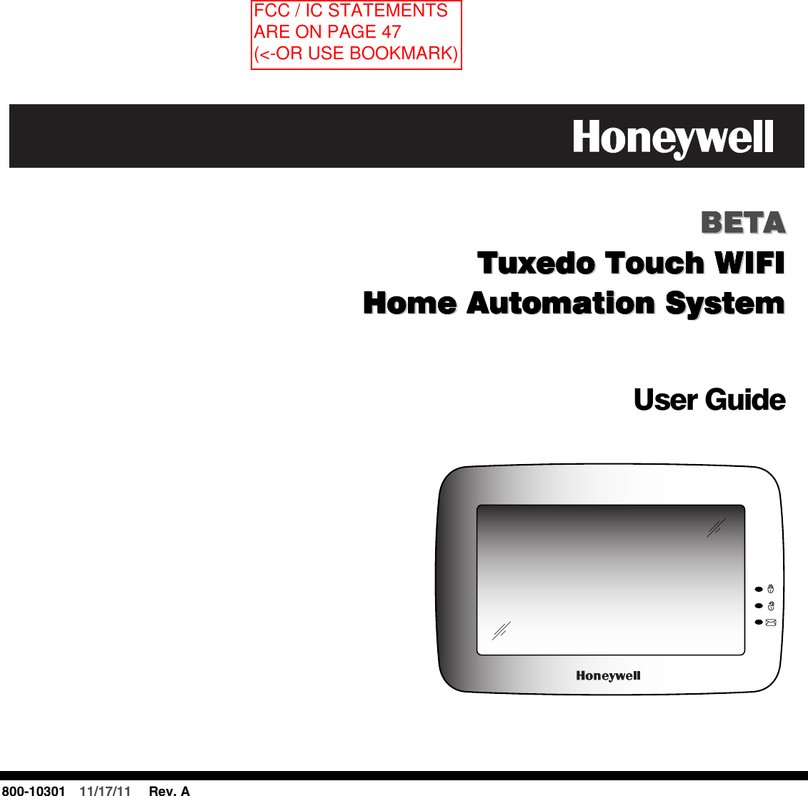
Ademco 8DL6280ZW Tuxedo Touch WIFI User Manual 800 10301 A ug 6280 WiFi

Honeywell International Inc. Tuxedo Touch WIFI 800 10301 A ug 6280 WiFi

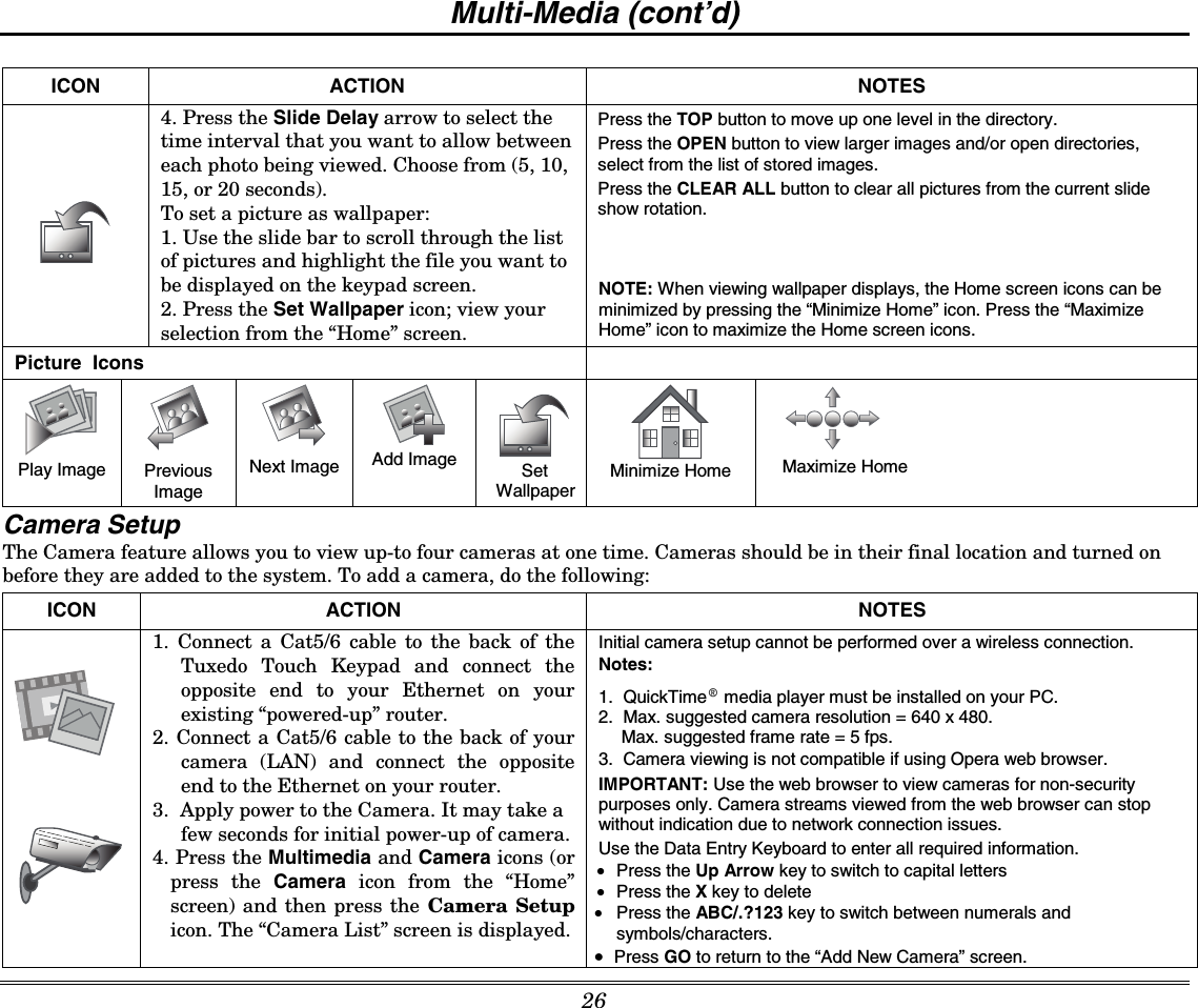
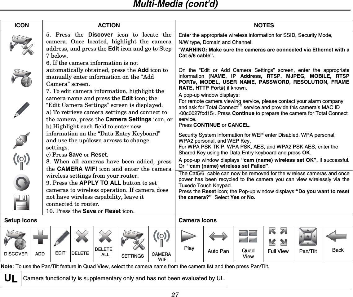
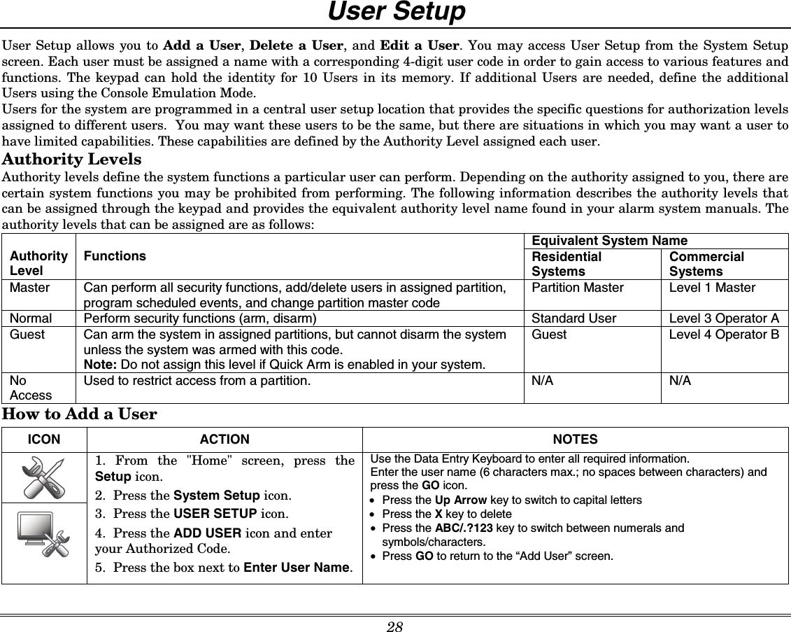
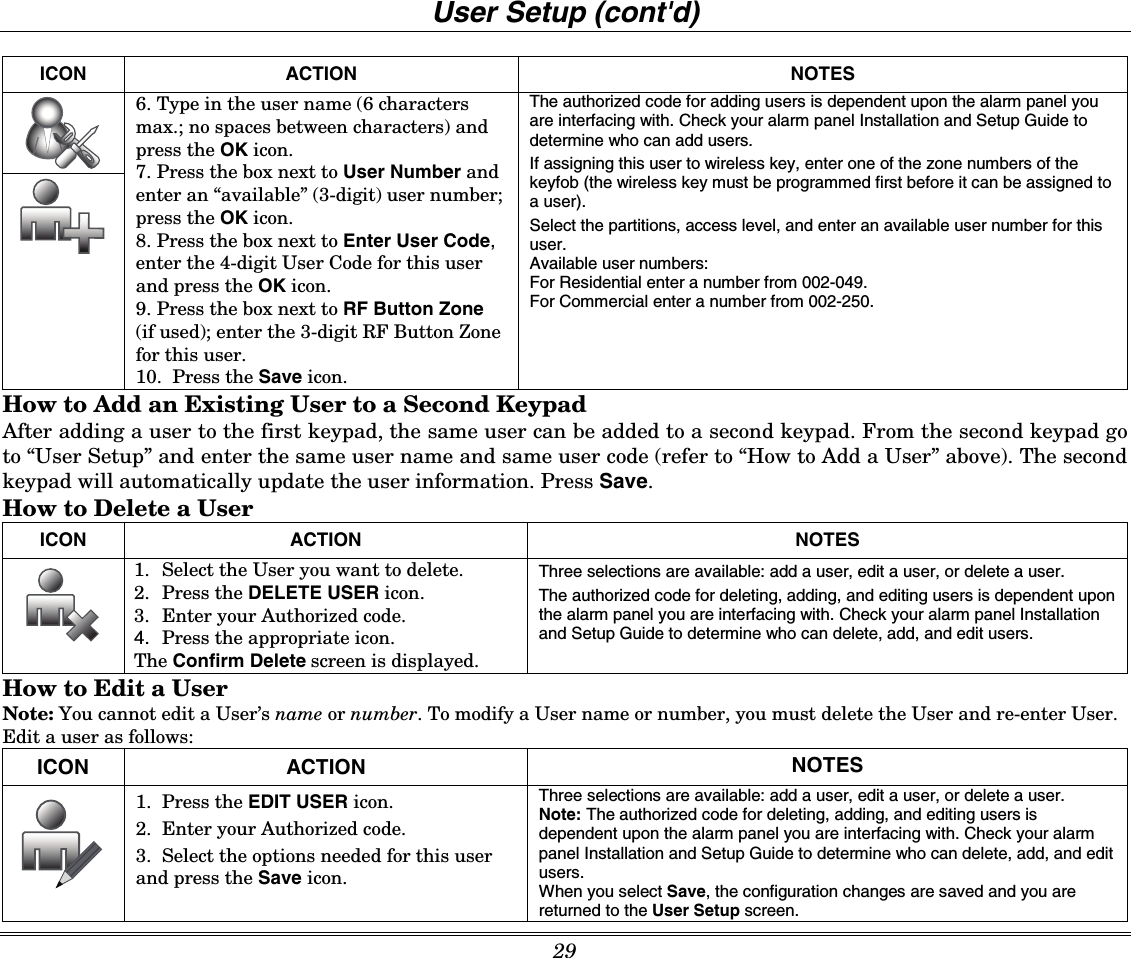
Users Manual User Revised

         BBBBBBBBEEEEEEEETTTTTTTTAAAAAAAA        TTTTTTTTuuuuuuuuxxxxxxxxeeeeeeeeddddddddoooooooo        TTTTTTTToooooooouuuuuuuucccccccchhhhhhhh        WWWWWWWWIIIIIIIIFFFFFFFFIIIIIIII        HHHHHHHHoooooooommmmmmmmeeeeeeee        AAAAAAAAuuuuuuuuttttttttoooooooommmmmmmmaaaaaaaattttttttiiiiiiiioooooooonnnnnnnn        SSSSSSSSyyyyyyyysssssssstttttttteeeeeeeemmmmmmmm          User Guide       800-10301  11/17/11   Rev. A      FCC / IC STATEMENTS ARE ON PAGE 47 (<-OR USE BOOKMARK)
Table of Contents  3  ABOUT THE SYSTEM ...............................................................................................................................................................................6 Introduction..........................................................................................................................................................................................6 System Interface...........................................................................................................................................................................6 Navigating through the Tuxedo Touch Keypad.............................................................................................................................6 About Your Home Screen.............................................................................................................................................................7 Multi-Media Application................................................................................................................................................................7 Weather Forecast.........................................................................................................................................................................7 System Troubles...........................................................................................................................................................................9 User Codes.................................................................................................................................................................................10 Extended Functionality...............................................................................................................................................................10 LED Operation............................................................................................................................................................................10 Safe Mode..................................................................................................................................................................................10 SECURITY................................................................................................................................................................................................11 Introduction to Security System Operation ........................................................................................................................................11 How to Arm the System..............................................................................................................................................................12 How to Arm Multiple Partitions....................................................................................................................................................12 How to Display Faults.................................................................................................................................................................13 How to Bypass Zones.................................................................................................................................................................13 How to Clear Bypassed Zones...................................................................................................................................................14 How to Disarm the System.........................................................................................................................................................14 To disarm Multi-Partitions do the following:................................................................................................................................15 How to Check the Status of Other Partitions..............................................................................................................................15 Fire and Carbon Monoxide Alarm Operation..............................................................................................................................16 In Case of Fire Alarm..................................................................................................................................................................16 Silencing and Clearing a Fire/Carbon Monoxide Alarm..............................................................................................................16 More Choices ....................................................................................................................................................................................17
Table of Contents  4  How to Clear/Hide a Control Panel Message.............................................................................................................................17 Advanced System Features........................................................................................................................................................17 Console Emulation Mode...........................................................................................................................................................17 How to Enter Console Emulation Mode......................................................................................................................................18 How to View the Event Log........................................................................................................................................................18 How to Send Emergency Messages...........................................................................................................................................18 SETUP......................................................................................................................................................................................................19 Brightness and Volume Control..................................................................................................................................................19 Display & Audio Setup.......................................................................................................................................................................19 Operation Modes........................................................................................................................................................................19 Adjust the Screen Timeouts........................................................................................................................................................20 Clean Screen..............................................................................................................................................................................20 Routine Care..............................................................................................................................................................................20 System Information.....................................................................................................................................................................21 IP Setup and Network Connections............................................................................................................................................21 Voice Messages ................................................................................................................................................................................24 Video (Audio) Setup...........................................................................................................................................................................25 Picture Setup .....................................................................................................................................................................................25 Camera Setup ...................................................................................................................................................................................26 Authority Levels..........................................................................................................................................................................28 How to Add a User.....................................................................................................................................................................28 How to Add an Existing User to a Second Keypad.....................................................................................................................29 How to Delete a User.................................................................................................................................................................29 How to Edit a User......................................................................................................................................................................29 Safe Mode..................................................................................................................................................................................30 Time/Date Setup................................................................................................................................................................................31
Table of Contents  5  Setting Daylight Savings Time....................................................................................................................................................31 Setting Current Time and Date...................................................................................................................................................32 Advanced Setup.........................................................................................................................................................................33 Output Setup Function................................................................................................................................................................33 AUTOMATION .........................................................................................................................................................................................34 Include/Add Z-Wave Devices ............................................................................................................................................................34 Editing Z-Wave Device Names...................................................................................................................................................36 Exclude/Delete Z-Wave Devices................................................................................................................................................37 Exclude/Delete a Door Lock.......................................................................................................................................................37 Exclude/Delete a Honeywell Thermostat....................................................................................................................................38 Exclude All Z-Wave Devices.......................................................................................................................................................38 Abort a Z-Wave Action...............................................................................................................................................................38 Output List..................................................................................................................................................................................39 Create a Scene...........................................................................................................................................................................39 Create a Group...........................................................................................................................................................................41 Setting a Secondary Controller...................................................................................................................................................41 Updating Controllers with New or Removed devices..................................................................................................................42 Removing a Secondary Controller..............................................................................................................................................42 Z-Wave Troubleshooting............................................................................................................................................................42 Compatible Devices....................................................................................................................................................................43 NOTES .....................................................................................................................................................................................................44 GLOSSARY..............................................................................................................................................................................................46     NOTE: This device is a Security Enabled Z-Wave Controller.
 6    About the System Introduction Congratulations on your ownership of a Honeywell Tuxedo Touch WIFI Home Automation System which combines home-automation and home security. With clear, simple controls on a touch-screen interface, Tuxedo Touch is both easy to learn and easy to use.  System Interface Equipped with Wi-Fi capability and built-in Z-Wave® technology, Tuxedo Touch WIFI can be retrofitted into home electronics devices and systems without interference from common household wireless electronics.  Features The Tuxedo Touch wireless keypad, used for quick and easy security system operation, offers Z-Wave control of the home environment, such as lights, appliances, thermostats, door locks and cameras via any web enabled device (PC, Smart Phone and Tablet). • Thermostats – temperature control for energy conservation when away from home. • Lights/Appliances - turn lights and appliances on when the security system is disarmed. • Door locks - door unlocks when the security system is disarmed. • Cameras – control and view up-to four cameras in quad view at the same time from any web enabled device.  In addition, this system offers you burglary protection and may provide fire, carbon monoxide and emergency protection. To realize the full potential of the system, it is important that you feel comfortable operating it.  Your system may consist of one or more of the following:  • TUXWIFIS  Keypad (black/silver housing) • TUXWIFIW Keypad (white housing) • One or more other keypads for system control  • Various sensors for perimeter and interior burglary protection, plus a selected number of strategically placed smoke, carbon monoxide or combustion detectors  • Lighting/output devices. The system uses microcomputer technology to monitor all zones, and provides appropriate information for display on the keypad and/or other keypads used with the system. Your system may also have been programmed to automatically transmit alarm or status messages over the phone lines or wirelessly over GSM to a central alarm monitoring station. UL  Wi-Fi has not been evaluated by UL.  Navigating through the Tuxedo Touch Keypad Navigation through the Tuxedo Touch Keypad typically begins from the "Home" screen.  This is the main default screen (starting screen) and is the first screen you see when you power up and initialize the keypad.  It is from this screen that you select from the main menu.  Once you have made your selection, you can navigate through various sub-menus by pressing graphical icons to perform the function you desire.
About the System (cont'd) 7 About Your Home Screen Your "Home" screen is the gateway to your System. From this screen you can: • control your security system  • control your multi-media applications such as video, pictures and cameras • control home automation such as lighting, thermostat, and door locks Your "Home" screen is displayed most of the time and can be customized via the Multi-Media Application.     Multi-Media Application The Picture/Video (Audio) features allow you to display personal photos (in a slide show format), and view video files via the external SD/SDHC card.  It is recommended that you use the SD/SDHC card supplied with the keypad.   In everyday handling, memory cards can become susceptible to malfunction and/or failure due to electrostatic discharges and the information on the card may be lost. In some extreme cases, the keypad may need to be reset.  NOTE: Honeywell is not responsible for any loss of personal information (files, videos, photos, etc.)     The background and icons shown on the “Home” screen in this manual are for example only. Your system installer may have changed the actual background and icons shown on your “Home” screen. Memory Card Insertion Insert the memory card (SD/SDHC Card) as shown.   Tips for proper memory card handling: • Avoid touching the contacts on the card • Quit the slide show/video application before removing the memory card. 6280-004-V0INSERTCARD Weather Forecast The weather forecast is displayed on the “Home” screen. To view the weather conditions for a specific location, press the Weather icon (on the “Home” screen) and select the box next to the information to be added for that location. Enter the location information on the data entry keyboard. Press the Back icon. The four day weather conditions for the location entered are displayed. Press the Refresh icon to update the screen. 38 F47 F43 FHigh LowMelville, NYTemp.
About the System (cont'd) 8 Navigation Icon Descriptions To aid in the navigation through the Tuxedo Touch WIFI screens, a set of user-friendly icons has been provided.  The appearance and function of these icons are described below.  ICON   ICON TITLE  FUNCTION  ICON  ICON TITLE  FUNCTION  “Product Video”  Accesses Product Introduction and Training Videos.   “Setup”  Accesses the Setup menus.  "Automation” Accesses the Z-Wave setup, Scene setup, and Room setup screens.   “Multimedia”  Accesses the Message, Camera, Picture and Video features.  "Security”  Accesses the "Security" screen.   “Video” Allows user to play video files.   “Home”  Returns you to the "Home" screen.    “Picture”  Allows user to display personal photos in a slide show format.  "Message”  Record and retrieve Voice Messages.   “Panic”  Displays Emergency functions (as programmed by the installer).  Note: This icon is displayed and active on all screens except while in the Clean Screen mode, during an LCD Display test in Diagnostics and from the Video and Camera screens.  “Voice Status”  Allows user to hear system status.  “Back”  Reverts to the last screen viewed.    “Control Panel Message” This icon alerts the user to a Control Panel Message.  Minimizing the Home Screen Icons When viewing wallpaper displays, the Home screen icons can be minimized by pressing the “Minimize Home” icon. Press the “Maximize Home” icon to maximize Home screen icons.              Minimize Home  Setup Picture Product Video Maximize Home  Security Automation Multimedia Weather Camera  Panic
About the System (cont'd) 9 System Troubles   The “Security” screen also displays an Icon(s) if a system trouble(s) occurs. If a Trouble Icon is shown, contact your alarm company. The following Icons may be shown as applicable to your system:  Note: If multiple faults exist, press the More Choices icon and then the Show Zones icon to view and scroll through the complete list of faults.ICON FUNCTION  AC Loss – The system is not receiving AC power.  Bell Failure – The system bell or siren has a problem. Note: This Icon displays when interfacing with residential panels only.  Expander Failure – The system has a failure in an expansion module.  Low Battery – The system battery, that powers the system during an AC power loss, is low.   LRR Supervision Failure – The Communication Device used to communicate with the central station has a supervision failure  Max Attempts Exceeded – The system has exceeded the maximum attempts to communicate with the Central Station.   Pager Failure – The system cannot communicate with an assigned pager.  Telco-1 Cut – The system is not able to communicate with the central monitoring station over the primary phone line.  Telco-2 Cut – The system is not able to communicate with the central monitoring station over the secondary phone line.  Wireless Failure – The system is not able to communicate with its wireless devices.
About the System (cont'd) 10 User Codes Each user must be assigned a name with a corresponding 4-digit user code in order to gain access to authorized features and functions. Users for the system are programmed in a central user setup location that provides the specific questions for authorization level, partition assignment, and RF zone assignment. Extended Functionality Extended functions are advanced functions that can be accessed through a standard alpha keypad or through the console emulation mode on your Tuxedo Touch touch-screen.  Refer to your Control Panel User Guide for these features.  LED Operation The Tuxedo Touch Keypad has three LEDs as follows: 6280-001-V0FLASHING – The system contains newmessage(s) for the User.OFF – No new messages.RESET BUTTONPress to reset keypadON – System is armed.OFF – System is not armed.ARMED (RED) LEDREADY (GREEN) LEDON – System is disarmed and ready to arm.OFF – System is armed or disarmed but notready. If disarmed, faults or troubles are present.MESSAGE (YELLOW) LEDSD/SDHC CARD Slot *Note:  If the EN50131 Display feature is enabled, the "Armed" and "Ready" status LEDs turn OFF after 30 seconds and the screen returns to the Home screen until a valid user code is entered.  Safe Mode The Keypad contains a Safe Mode of operation. In the rare event that the keypad cannot successfully communicate in its graphic mode with the control panel, the Safe Mode is a backup mode that ensures that you can communicate with your system. Refer to the Safe Mode section for further information.
 11 Security Introduction to Security System Operation You can arm your system in one of three arming modes: Away, Stay, and Night.  The following table lists the three different arming modes and the results of each. FEATURES FOR EACH ARMING MODE Arming Mode FUNCTION Exit Delay Entry Delay Perimeter Armed Interior Armed AWAY  Press to arm when no one is staying on the premises.  When armed in AWAY, the system sounds an alarm if a protected door or window is opened, or if any movement is detected inside the premises.  Yes Yes  Yes  Yes STAY  Press to arm when you are staying home, but might expect someone to use the entrance door later.   When armed in STAY, the system sounds an alarm if a protected door or window is opened, but you may otherwise move freely throughout the premises.  Yes Yes  Yes  No NIGHT  Press to arm when you are staying home and do not expect anyone to use the entrance door. Your installer may have configured NIGHT Mode differently; have the installer describe the actual settings of this mode.  Yes Yes (set for Away or Stay Mode) No (set for Instant or Maximum Mode) Yes Yes (set for Away or Maximum Mode) No (set for Stay or Instant Mode) Important: On Commercial systems, “Away Auto Stay” mode is shown as “Away” mode (with all zones monitored). However, some interior zones may not be armed. Note: The Voice Status Icon (  ) indicates the Voice feature. Press the Voice Status Icon to hear system status. Wait 3 seconds and press again to hear Zone Faults or Trouble conditions. Voice status will annunciate even if Voice mode and Chime mode are disabled. Note that the Voice feature must be enabled (by the installer) for this icon to function correctly during an alarm condition.  Note: There is a communicator delay of 30 seconds. This delay will prevent a report to the central station if the control panel is disarmed within 30 seconds after an intrusion alarm is triggered. This delay can be removed, or it can be increased up to 45 seconds at the option of the user by consulting with the installer. Note that emergency, carbon monoxide, and fire-type alarms are normally reported without delay.
Security (cont’d) 12 How to Arm the System Arming the system in any mode is performed in the same way, as described below. Note:  Close all perimeter windows and doors before arming. Arm the system as follows: ICON ACTION  NOTES   1. From the “Home” screen, press the SECURITY icon.  2.  Press the selected arming icon.   -a text message appears stating which zones are arming and whether or not there is an entry delay -the screen changes to display the remaining exit delay time, and  -the exit delay time continues to count down to one.   Note: If Quick Arm is Not enabled in your system, a message to enter your User Code is received. When the system is armed for Stay, Night Stay and Instant mode, the keypad beeps 3 times. When the system is armed for Away and Maximum mode, you will hear steady beeps then rapid beeping during the last 10 seconds of Exit Delay.   When exit delay time expires, the screen automatically changes to indicate the system is "Armed".  Note: For CP-01 installations, Maximum Mode cannot be used. How to Arm Multiple Partitions Note: Some systems may not have multiple partitions and the “Arm Multi-Partitions” icon may not be displayed. To arm multiple partitions: ICON ACTION  NOTES   1. From the “Home” screen, press the Security icon and then the Arm Multi-Partition icon.  2.  Select the appropriate arming mode. 3. Enter the User Code authorized to access other partition(s).   4. Highlight the partition from the list on the screen, and press OK. 5. Select ALL to arm all partitions listed. Notes:  •  A user may have access to some or all of the available partitions. •  If the user code is accepted, the system displays the partitions that the user has access to.   When exit delay time expires, the screen automatically changes to indicate the system is "Armed".   Note: If any zones are bypassed, a “Display Faults” (    ) icon is displayed on this screen.
Security (cont'd) 13 How to Display Faults The Display Faults function is used when you see a “Not Ready Fault” message and want to determine where the fault is and what type of fault it is.  To display faults do the following: ICON ACTION   NOTES    1. From the "Security" screen, press the DISPLAY FAULTS icon.    A listing of faulted and/or bypassed zones is displayed.  As applicable, take corrective action such as closing a window or door to correct the fault.  2. If the fault cannot be corrected, you may choose to bypass a zone by pressing the zone and highlighting it and then pressing the BYPASS SELECTED icon.  Show Zones Icons  Distressed Zones Icons  Clear Bypasses   Refresh Data      Bypass Selected      Bypass All      Distressed Zones   Alarm   Troubles     Faults   Bypass Zones  Low Battery   All How to Bypass Zones The Bypass function is used when you want to arm your system with one or more zones left open. Bypassed zones are unprotected and do not cause an alarm when violated while your system is armed.   •  Residential systems do not allow you to bypass fire, carbon monoxide or emergency zones. On commercial fire systems, a specified user may be allowed to bypass fire, carbon monoxide and system zones if the user was enabled by your system installer. •  Limits apply as to how many zones can be bypassed at one time. These limits are ten zones on residential systems and five zones on commercial systems.
Security (cont’d) 14 To bypass zones do the following: ICON ACTION   NOTES  1. From the “Home” screen, press the SECURITY icon.   2.  Press the MORE CHOICES icon.   Note: If any zones are bypassed or faulted, a Display Faults icon is also displayed on this screen.  3.  Press the SHOW ZONES icon.  While the keypad is requesting and receiving the zone data from the control panel, the screen displays "Please Wait!". Then the zones, along with their current status, are displayed.   4.  Highlight the zone(s) to be bypassed and press the BYPASS SELECTED icon. 5.  Enter your 4-digit user code.   Note: If zones have already been bypassed, the top of this screen indicates “Ready Bypass”.   The screen is displayed with the instructions "To Bypass Zones, Enter Code".  6. Press the BACK icon to return to the “Arming” screen. The "More Choices" screen is displayed showing the system status as Ready-Bypass.   How to Clear Bypassed Zones A bypassed zone is automatically unbypassed when you disarm the system.  If a zone is bypassed, you can remove the bypass as follows: ICON ACTION   NOTES  1.  Press the SHOW ZONES icon.   While the keypad is requesting and receiving the zone data from the control panel, the screen displays "Please Wait!". Then the zones, along with their current status, are displayed.  2. Press the CLEAR BYPASSES icon.  3. Enter your 4-digit user code.  The "More Choices" screen is displayed showing the system as Ready to Arm. Note:  If the system is armed and you unbypass a zone, it disarms the system. If zones are still faulted (not ready) the system will indicate the status as “Not Ready Fault”.    How to Disarm the System IMPORTANT: If you return to your home or business and the main burglary sounder is on, DO NOT enter the premises, but call the police from a nearby safe location. If you return to your home or business after an alarm has occurred and the main sounder has shut itself off, the keypad beeps rapidly upon entering, indicating that an alarm has occurred during your absence. LEAVE IMMEDIATELY and CONTACT THE POLICE from a nearby safe location.
Security (cont'd) 15 The system may be disarmed using either of two methods. One method is employed when you enter the premises and the other is when you have been in the premises with the system armed (i.e., Stay and Night arming modes). To disarm the system when entering the premises: The keypad automatically displays the Entry Delay Active screen when you enter the premises: ICON ACTION  NOTES  1. Enter your 4-digit user code.   The partition is disarmed and the "Arming" screen is displayed showing the system as Ready to Arm. Note: If you have a commercial system and a time window has been defined for when you may disarm the system, the system does not disarm if you are outside that time window. To disarm the system when already in the premises:  ICON ACTION   NOTES  1. Press the Disarm icon. 2. Enter your 4-digit user code.     To disarm Multi-Partitions do the following:  ICON ACTION   NOTES  1. From the “Home” screen, press the Security icon. 2. Press the Arm Multi-Partition icon. 3. Press the Disarm icon. 4. Enter your 4-digit user code.   5. Highlight the partition(s) to disarm and press OK, or press ALL to disarm all partitions. The keypad displays “Multi-Partition Arming”. How to Check the Status of Other Partitions This system supports between one and eight Partitions (depending on the system.)  Partitioning enables a single physical alarm system to control up to eight areas of protection (partitions) depending on the system you have purchased. Each Touch-Screen keypad is assigned a default partition for display purposes, and shows only that partition's information.  Note: A letter “H” following the partition name or number indicates that this is the default partition for the keypad. For example, if your physical site is a four-apartment housing unit, your alarm system may be configured with four partitions. Each apartment’s zones (door, windows, smoke detectors, etc.) are assigned to separate partitions, giving each apartment independent arming/disarming control of its own partition (area).  A landlord or manager may be granted access to all partitions, so he/she can control the entire system. If a user is so authorized, a keypad or other keypad in one partition can be used to perform system functions in another partition. (Note that only those partitions authorized and programmed by the installer can be accessed in this manner.)
Security (cont’d) 16 To check the status of other partitions perform the following:  ICON   ACTION  NOTES  1.  Press the SECURITY icon.   2.  Press the "Current Partition" icon (lower edge of the screen; in this case it displays P1 H unless changed by installer).   3.  Enter the code authorized to access other partition(s).   If the code is accepted, the system displays the partitions that user has access to.   This screen displays the available partitions and their current status.   The current partition is shown at the top of the display (P1).  To change this assignment, select the appropriate icon (e.g., press P2 to switch control to Partition 2). Note: After leaving this screen when using a residential panel, the selected partition in the keypad automatically reverts back to the keypad’s home partition after two minutes. When using commercial panels, you must select the keypad’s home partition to return to it. Note:  A code may have access to some or all of the available partitions. Fire and Carbon Monoxide Alarm Operation Your fire alarm system and carbon monoxide detector (if installed) is on 24 hours a day, providing continuous protection.  In the event of an emergency, the installed smoke, heat, carbon monoxide detectors automatically send signals to your Control/Communicator, triggering a loud interrupted sound from the keypad.  An interrupted sound is also produced by optional exterior sounders. EVACUATE ALL OCCUPANTS FROM THE PREMISES IMMEDIATELY. Notify your Central Station/Security Company immediately and wait for further instructions. UL  CO annunciation has not been investigated by UL and may not be used for UL installations. In Case of Fire Alarm 1. A FIRE message appears at your keypad and remains on until you silence the alarm. 2. Should you become aware of a fire emergency before your detectors sense the problem, go to your nearest keypad and manually initiate an alarm by pressing the panic key assigned as FIRE emergency (if programmed by the installer) and hold down for at least 2 seconds. 3. Evacuate all occupants from the premises. 4. If flames and/or smoke are present, leave the premises and notify your local Fire Department immediately. Silencing and Clearing a Fire/Carbon Monoxide Alarm 1. Silence, acknowledge, and clear the alarm by: a.  For Residential Systems: Press “Touch here to Silence” on the display to silence the alarm.  For Commercial Systems: Enter your code. This silences and acknowledges the alarm and disarming of the system (if armed). b.  For Residential Systems: Press the CLEAR icon followed by your code. This acknowledges the alarm and the disarming of the system (if armed). For Commercial Systems: Press the CLEAR icon followed by your code. The system attempts to clear the alarm from memory. If NOT successful (i.e., smoke in the detector) the Security screen is displayed and the Display Faults icon displays a “Not Ready Fault”. c. Press the DISPLAY FAULTS icon on the Arming screen. The faulted fire/carbon monoxide zone is displayed.
Security (cont'd) 17 d. Press the CLEAR icon and then enter your code. This clears the Fire Alarm/CO Alarm from the system.  2. If the keypad does not indicate a READY condition after the second sequence, press the DISPLAY FAULTS key on the Arming screen to display the zone(s) that are faulted.  Be sure to check that smoke detectors/carbon monoxide detectors are not responding to smoke, heat, or gas producing objects in their vicinity.  In this case, eliminate the source of heat, smoke or leak. 3. If this does not remedy the problem, there may still be smoke/gas in the detector.  Clear it by fanning the detector for about 30 seconds. 4. When the problem has been corrected, clear the display by entering the DISPLAY FAULTS icon on the Arming screen, selecting the fire or carbon monoxide zone, pressing the CLEAR icon and then entering your user code. Note: Contact your Central Station/Security Company for servicing if you have further problems with your system. More Choices How to Clear/Hide a Control Panel Message The Control Panel Message icon alerts the user to a control panel message. When a Control Panel Message is displayed, the user has two options. User can clear the Control Panel Message immediately, or minimize the window and clear it at a later time.  To Clear/Hide the Control Panel Message, do the following:  ICON ACTION   NOTES  1. To clear; press CLEAR.   2. Enter your Authorized Code or, 3. To hide; press HIDE to clear the Control Panel Message later. Once your Authorized Code is accepted, the Control Panel Message is cleared.  If the alarm is still present, press CLEAR again and then enter your Authorized Code again. Press the HIDE icon to address the condition later. Advanced System Features While most of the commonly used security functions are available from the keypad’s advanced user interface, there are some less used, advanced features that can either be accessed through Console Emulation mode on the keypad or a standard alpha keypad.  To use features not supported by the keypad, refer to your Control Panel User Guide. Console Emulation Mode Console Emulation Mode allows you to use a keypad interface just as you would a regular system keypad.  All commands shown in Console Emulation mode can also be executed from a standard alpha keypad. Notes: •  It is recommended that you do not use the Console Emulation Mode to enter GOTO commands. Unsatisfactory operation may result from issuing GOTO commands in Console Emulation. •  Two icon panics (1 & *, 3 & #, and * & #) do not function in the Console Emulation Mode. The A, B, C, and D icons do function if programmed as panic keys. Check with your system installer for details. •  Commercial systems with Alpha keypads have a feature where if you press a key for 5 seconds, you receive self help messages about the pressed key or holding the * key for 5 seconds to provide zone descriptors. These features do not function in the keypad as all key presses are instantaneous.
Security (cont’d) 18 How to Enter Console Emulation Mode To access Console Emulation Mode, do the following: ICON ACTION  NOTES  1. From the Home screen, press the SECURITY icon.   2. Press the MORE CHOICES icon.     3. Press the CONSOLE MODE icon.    Perform functions as you would from a standard alpha keypad. How to View the Event Log  Your system has the ability to record various events in a history log wherein each event is recorded with the time and date of its occurrence.  The control panel must be programmed to record various system events in the installer programming mode.  To view the Event Log, perform the following: ICON ACTION   NOTES  1.  From the “Home” screen, press Security and then the MORE CHOICES icon.   2.  Press the EVENT LOGS icon.   The first ten events are displayed. Note: While keypad is requesting and receiving the event log data from the control panel, the "Event Log" screen displays "Please Wait!" The Next>> and <<Previous icons are shown for commercial panels only when 100 or more events are in the log. They are not shown for residential panels.  3. Press the SHOW MORE button to view all items, and press the up/down arrows to scroll through the event log.   When All Partitions or All Events icon is pressed, and more than 100 events exist, the Next>> and <<Previous icons are displayed showing the next 100 or previous 100 events. How to Send Emergency Messages An emergency message for fire, panic, or medical can be sent to the central monitoring station from the Emergency screen.  The Emergency screen can be accessed by activating the "PANIC" Icon located on the lower right corner of the screen. Perform the following to send an emergency message. ICON   ACTION  NOTES  1. Press the PANIC Icon. 2. Press and hold (for at least 2 seconds) the associated alarm icon (FIRE, PANIC, SILENT PANIC or MEDICAL).   You are immediately returned to the screen from which you pressed the “PANIC” Icon. NOTE: The Emergency screen cannot be accessed while running a screen diagnostic test or while in the clean screen mode.   Emergency Icons  Fire   Panic    Silent Panic  Medical • Emergency messages are optional and may not be available on your system. Ask your system installer if emergency messages are available on your system. NOTE: Medical functionality has not been evaluated by UL and may not be used in UL Listed applications.
 19  Setup Setup allows you to make changes to the way your keypad is operating. You may access the Brightness and Volume, Display & Audio Setup, and System Setup from the "Setup" screen.  Brightness and Volume Control From the "Home" screen, access the "Setup" screen as follows: ICON ACTION  NOTES  1.  Press the Setup icon.   2. Move the Brightness/Volume slide bar up or down to increase or decrease settings.  If changes are made, when you exit a Settings Changed! pop-up window is displayed asking “Remember New Settings?“ Yes saves the change. No discards the change. Display & Audio Setup You may access Operation Modes, Backlight Off After time, To Homepage After time, Auto Slideshow After time and Clean Screen from Display & Audio Setup. Operation Modes  Operation modes provides access to Chime Mode, Voice Mode, and Voice Chime which allows you to turn the keypad chime mode and voice mode on or off.   •  Chime Mode – Keypad chimes whenever a door or window is open. •  Voice Mode – Keypad voice annunciates whenever a change in system status occurs.  •  Voice Chime – The chime mode and voice mode are in effect with the chime beeps followed by voice annunciation. Access the "Operation Modes" screen as follows: ICON ACTION  NOTES  1. From the “Setup” screen, press the Disp & Audio Setup icon.  2.  Enter your “Authorized Code", if required.  If the Chime Mode and Voice Mode are both selected, the Voice Chime is automatically selected.   3.  Select Chime Mode or Voice Mode to turn the mode on or off.  4. Press the HOME or BACK icon after making your selection. It may take a few seconds for the Chime Mode to take effect. When the keypad exits the “Operation Modes” screen, your selection is saved.
Setup (cont’d) 20 Adjust the Screen Timeouts When the keypad is left idle, it automatically:  • turns the “Backlight Off After” the selected backlight off time has expired (unless “Never” option is selected).   • returns to the “Home” screen after the selected “To Homepage After” time has expired (unless “Never” option is selected), and • if enabled, the “Auto Slideshow After” time begins the slide show.  To select the desired screen timeouts, do the following: ICON ACTION  NOTES   1. From the "Home" screen, press the Setup icon.   2. Press the Disp & Audio Setup icon. 3. Enter your “Authorized Code", if required.  4. Press the desired selection from the drop-down list displaying the time period for each option. Yes saves the change.  No discards the change. If changes are made, when you exit a  Settings Changed! pop-up window is displayed asking “Remember New Settings?“  Settings include: • Backlight Off After X time • Return To Homepage After X time • Auto Slideshow After X time. Note 1: The “To Homepage After” option is only available if the EN50131 display option is not enabled by the installer. Note 2: When in EN50131 mode, “Auto Slideshow After” is preset to “1” minute and can not be changed. Clean Screen With the exception of normal cleaning, the keypad is maintenance free.  Clean the touch-screen as follows: ICON ACTION  NOTES    1. From the “Home” screen, press the Setup icon. 2. Press the Disp & Audio Setup icon.  3.  Enter your “Authorized Code", if required. 4. Press the CLEAN SCREEN icon to disable the keypad for 30 seconds so you can wipe the screen clean. 5. Press Continue to disable the touch-screen. 6. Press Cancel to exit. At the "Touch Screen Disabled for =30 Seconds" screen, the touch-screen should be wiped clean of fingerprints using a mild soap solution and a soft cloth. When the counter reaches zero, the window automatically closes and the touch-screen is active.  NOTE: The Emergency screen cannot be accessed while running in the clean screen mode. A pop-up window displays "Touch Screen will be disabled so that you may wipe the screen clean. Please use a damp, soft cloth. DO NOT use any liquids, sprays, or ammonia-based cleaners. Press CONTINUE to disable touchscreen." **Panics cannot be initiated during this process**  IMPORTANT:  Do not use an abrasive cleaning agent or abrasive cloth when cleaning the touch-screen or damage to the touch-screen may occur.  Routine Care • Treat the components of your security system as you would any other electrical equipment. Do not slam sensor-protected doors or windows. • Keep dust from accumulating on the keypad and all protective sensors, particularly on motion sensors and smoke detectors. • The keypad case and sensors should be carefully dusted with a dry soft cloth. Do not spray water or any other fluid on the units.
Setup (cont'd) 21 System Information  To view the latest software/firmware version installed on your system, do the following: ICON ACTION  NOTES  1. From the “Home” screen, press the Setup icon.   2. Press the System Info icon.  The Software and Firmware Version is displayed on the left side of the screen. IP Setup and Network Connections To set up a wireless network, you need a broadband or high-speed Internet connection (not a dial-up connection) provided by an Internet service provider (ISP).  Web Server/Hosting The Tuxedo Touch keypad offers built-in web hosting capability to access your Security and Home Automation System via any web enabled device. The Tuxedo Touch keypad IP Address is displayed on the “IP Setup” screen as well as on the “Home” screen. This IP Address is used on a standard web browser to control user functions. IP Address Setup In most cases, IP addresses are assigned ‘automatically’ (Automatic IP Address) by your Internet Service Provider. If not, you may require a “Static” (Fixed) IP Address. Obtain that address by contacting your Internet Service Provider.  To enable access to the Tuxedo Touch keypad options from any web enabled device, do the following: ACTION NOTES 1. At your PC, Smart Phone or Tablet: a) Navigate to the Settings feature.  b) Turn ON the “Wi-Fi” setting and select the router to connect to. Enter a name and password, if required. c)  Open the browser and enter the IP Address displayed on the keypad into your browser.  After proper connection: •  Access to basic arming commands is available if using a Smart Phone or Tablet browser. • Full access to keypad options is available if using a PC browser. The IP Address is displayed in the lower left-hand corner on the Tuxedo Touch Keypad “Home” screen.  Network Connections To set up network connections, from the “Home” screen, and do the following:   ICON ACTION  NOTES    1. At the Tuxedo Touch keypad: a)  Press the Setup icon.  b)  Press the IP Setup icon.  2. Select a type of network connection: LAN or WIFI and go to that section below for further information.
Setup (cont’d) 22   UL  Web Server/Hosting is not Listed for use in UL installations. Remote arming/disarming/programming is not to be used in UL Listed Installations.  Setup a LAN Connection From the IP Setup screen, add a LAN network connection as follows: ICON ACTION  NOTES           1. At the Tuxedo Touch keypad: a) Press the LAN ON button.  Use the Up/Down arrow to select the “Internet Connection type”. - Select “Obtain address automatically” (to have the keypad begin to scan for existing networks to connect to automatically).  - Select Static IP to enter a “Fixed IP address” by pressing the first set of 3 zeros (“000”) on the screen, and enter the first three numbers of the address on the “Data Entry Keyboard”. Repeat this step until the complete address has been entered and press Apply. 3. Highlight the remaining fields and enter the required information for IP Address, Subnet Mask, Default Gateway, and DNS Server. 4. Press the Save icon.   A pop-up window displays: This will switch off WLAN Network, do you want to continue? Yes or NO Use the Data Entry Keyboard to enter the required information.  •  Press the “up arrow” to switch to capital letters. • Press the Space key to add a space between characters.  • Press the x key to delete/backspace. • Press the ABC/123 key to switch between numerals and symbols/characters. • Press GO to return to Account Setup.  A pop-up window displays: Network Details Saved  5. Press the Refresh icon; the IP information will automatically update. This may take up to 60 seconds. 6.  At your PC, Smart Phone or Tablet browser, start your browser and enter your IP Address.   After proper setup, the IP Address is displayed on the “Home” page.
Setup (cont'd) 23 Setup a WLAN (Wi-Fi) Connection From the IP Setup screen, add a WLAN network connection as follows: ICON ACTION  NOTES         1. At the Tuxedo Touch keypad: a) Press the WIFI ON button.   - Highlight the field from the list of  Wi-Fi Networks to connect to. - Or select Add Network. b) Highlight each field and enter the required information for SSID, Security Mode, and Passphrase/Shared Key.  c) Press the Save icon. 2. Press the Refresh icon; the information will automatically update. This may take up to 60 seconds. 3.  At your PC, Smart Phone or Tablet browser, start your browser and enter your IP Address.   A pop-up window displays: This will switch off LAN Network, do you want to continue? Yes or No Use the Data Entry Keyboard to enter the required information.  •  Press the “up arrow” key to switch to capital letters. •   Press the Space key to add a space between characters.  • Press the x key to delete/backspace. • Press the ABC/.?123 key to switch between numerals and symbols/characters. • Press the “#+=” key to switch to symbols. • Press GO to return to Account Setup. A pop-up window displays: Network Details Saved A pop-up window displays the message: Settings saved.  Select OK to save.  Account Setup Account Setup allows you to a set up an Account for up to 5 users. Create a user account as follows: ICON ACTION  NOTES    1. Press the Account Setup button. 2. Highlight the User Name/Password fields on the list and enter the data for each on the “Data Entry Keyboard”; press GO.  3. Press the Save icon. The new user is displayed on the screen. 4. Press the Clear  button to clear the User information.   A Confirmation window displays the message: Settings saved.    The ENABLED button is displayed when a successful network connection is completed.
 24 Multi-Media The Multi-Media feature allows you access voice messages, play video files, display a slide show of personal photos, and view up-to four cameras at once from your keypad. UL  Multi-Media functionality is supplementary only and has not been evaluated by UL. Voice Messages The Tuxedo Touch Keypad can record voice messages for others on the premises. The number of messages is not limited; however, the total time of all messages added together cannot exceed 120 seconds. Note: The voice messages are stored in the memory and all messages are lost if the keypad loses power or if it is reset. Recording/Retrieving Messages Voice messages are recorded and retrieved using the “Message Center” screen. To access messages, do the following: ICON ACTION  NOTES  1. From the Home screen, press the Multimediaicon and then press the Message icon.   2. Enter your Authorized code; the “Message Center” screen is displayed.   3. Press the RECORD icon and record your message while staying within approximately one foot of the keypad and speaking at a normal voice volume.  4. Press the STOP icon when you are done recording the message.    5. To listen to a voice message, highlight the message and then press the PLAY icon.  6.  To listen to the next message or previous message, press the NEXT or PREV icon.  7. To delete the selected message, press the DELETE icon. 8. To delete all messages, press the DELETE ALL icon. 9. To exit, press the Back or Home icon. Each message is numbered, dated and the length of the message in seconds (Sec) is displayed on the message list. As you are recording your message, the remaining time counter counts down to indicate the total remaining time available and a “Recording New Memo…” message is displayed above the message list window. To record additional messages, repeat steps 3 and 4.  The message indicator flashes and the message is listed in the message list window.  Use the slide bar to raise and lower the message volume. As the message is being played, a “Play (#): Voice Memo…” message is displayed above the message list window. When the end of the message is reached, the playback stops. Note: The Message LED will continue to flash until all new messages have been played back entirely. Highlight the message to delete and press the DELETE icon. A confirmation window is displayed stating:  Del Selected    Selected Memo 2: 11/02/12  00:30:00 Select Yes or No. Press the DELETE ALL button to delete all messages: A confirmation window is displayed stating: “Confirmation”   Do you want to delete all messages? Select Yes or No. Message Icons  RECORD  PREVIOUS  PLAY  NEXT  DELETE  DELETE ALL   HOME  BACK
Multi-Media (cont'd) 25  Video (Audio) Setup To access the Video and Audio feature, from the “Home” screen, do the following: ICON ACTION  NOTES  1. Insert your personal media (SD/SDHC) card (with stored video files) first. 2. Press the Multimedia icon and then press the Video icon. A Video Converter is required to convert videos for proper playback on the Tuxedo Touch Keypad. Use an Internet search engine to locate and download a Video Converter, then follow the steps in the Video Converter Instructions (provided in the carton).  3. Highlight a video file from the list and press the Play icon to start the selected video. 4. Press the Repeat icon to continually replay the selected video.   5. Deselect the Repeat icon to automatically play the complete list of video files starting with the first video and ending with the last. Notes:  •  If the video file causes the keypad to lock, use a small object (such as a paper clip) to press the reset button located in the lower right-hand side of the keypad to reset the keypad. •  Maximum video resolution should not exceed 400 x 240.  • Videos can not be played when the EN50131 Display is turned ON.    Video Icons  Play  Pause  Full View  Repeat  Stop  Use the slide bar to scroll through the video list.  Press the appropriate icon to Play, Pause, view a Full View, Stop or Repeat the video. To exit Full View mode at any time while a video is playing, press anywhere on the screen. Picture Setup  This feature allows the user to display personal photos on the keypad and can be accessed by pressing the Picture icon on the Home screen, or access this feature as follows: ICON ACTION  NOTES   1. Insert your personal media (SD/SDHC) card (with stored files) first. 2. Press the Multimedia icon, and then press the Picture icon.  3.  Select the type of viewing transition desired by pressing the Transition arrow.  Select from (Standard, Horizontal, Vertical or Fade Out). Photo files can be viewed from the (SD/SDHC) Card.  Formats supported are .bmp, png or .jpg files. NOTES:  •  To exit slide show at any time and resume keypad operation, press anywhere on the screen. •  The first image is displayed and a list of stored images appears on the screen.  •  When an image is loading, no other Picture Setup functions can be performed (play, remove, add or set wallpaper).
Multi-Media (cont’d) 26  ICON ACTION  NOTES     4. Press the Slide Delay arrow to select the time interval that you want to allow between each photo being viewed. Choose from (5, 10, 15, or 20 seconds). To set a picture as wallpaper: 1. Use the slide bar to scroll through the list of pictures and highlight the file you want to be displayed on the keypad screen.  2. Press the Set Wallpaper icon; view your selection from the “Home” screen. Press the TOP button to move up one level in the directory. Press the OPEN button to view larger images and/or open directories, select from the list of stored images. Press the CLEAR ALL button to clear all pictures from the current slide show rotation.   NOTE: When viewing wallpaper displays, the Home screen icons can be minimized by pressing the “Minimize Home” icon. Press the “Maximize Home” icon to maximize the Home screen icons.  Picture  Icons   Play Image  Previous Image  Next Image  Add Image  Set Wallpaper  Minimize Home         Maximize Home  Camera Setup The Camera feature allows you to view up-to four cameras at one time. Cameras should be in their final location and turned on before they are added to the system. To add a camera, do the following: ICON ACTION  NOTES      1. Connect a Cat5/6 cable to the back of the Tuxedo Touch Keypad and connect the opposite end to your Ethernet on your existing “powered-up” router.  2. Connect a Cat5/6 cable to the back of your camera (LAN) and connect the opposite end to the Ethernet on your router. 3.  Apply power to the Camera. It may take a few seconds for initial power-up of camera. 4. Press the Multimedia and Camera icons (or press the Camera icon from the “Home” screen) and then press the Camera Setup icon. The “Camera List” screen is displayed. Initial camera setup cannot be performed over a wireless connection.  Notes:  1.  QuickTime® media player must be installed on your PC.  2.  Max. suggested camera resolution = 640 x 480.  Max. suggested frame rate = 5 fps.  3.  Camera viewing is not compatible if using Opera web browser. IMPORTANT: Use the web browser to view cameras for non-security purposes only. Camera streams viewed from the web browser can stop without indication due to network connection issues. Use the Data Entry Keyboard to enter all required information.  • Press the Up Arrow key to switch to capital letters • Press the X key to delete • Press the ABC/.?123 key to switch between numerals and symbols/characters. • Press GO to return to the “Add New Camera” screen.
Multi-Media (cont'd) 27  ICON ACTION  NOTES Enter the appropriate wireless information for SSID, Security Mode, N/W type, Domain and Channel. “WARNING: Make sure the cameras are connected via Ethernet with a Cat 5/6 cable”.  On the “Edit or Add Camera Settings” screen, enter the appropriate information (NAME, IP Address, RTSP, MJPEG, MOBILE, RTSP PORT#, MODEL, USER NAME, PASSWORD, RESOLUTION, FRAME RATE, HTTP Port#) if known. A pop-up window displays: For remote camera viewing service, please contact your alarm company and ask for Total ConnectTM service and provide this camera’s MAC ID ‹00c0027fcd15›. Press Continue to prepare the camera for Total Connect service.  Press CONTINUE or CANCEL. Security System information for WEP enter Disabled, WPA personal, WPA2 personal, and WEP Key. For WPA PSK TKIP, WPA PSK, AES, and WPA2 PSK AES, enter the Shared Key using the Data Entry keyboard and press OK.  A pop-up window displays “cam (name) wireless set OK”, if successful. Or, “cam (name) wireless set Failed”.            5. Press the Discover icon to locate the camera. Once located, highlight the camera address, and press the Edit icon and go to Step 7 below.  6. If the camera information is not automatically obtained, press the Add icon to manually enter information on the “Add Camera” screen. 7. To edit camera information, highlight the camera name and press the Edit icon; the “Edit Camera Settings” screen is displayed.  a) To retrieve camera settings and connect to the camera, press the Camera Settings icon, or b) Highlight each field to enter new information on the “Data Entry Keyboard” and use the up/down arrows to change settings.  c) Press Save or Reset.  8. When all cameras have been added, press the CAMERA WIFI icon and enter the camera wireless settings from your router.  9. Press the APPLY TO ALL button to set cameras to wireless operation. If camera does not have wireless capability, leave it connected to router. 10. Press the Save or Reset icon. The Cat5/6  cable can now be removed for the wireless cameras and once power has been recycled to the camera you can view wirelessly via the Tuxedo Touch Keypad. Press the Reset icon; the Pop-up window displays “Do you want to reset the camera?”  Select Yes or No. Setup Icons Camera Icons   DISCOVER   ADD  EDIT  DELETE  DELETE ALL   SETTINGS   CAMERA WIFI   Play  Auto Pan  Quad View  Full View  Pan/Tilt  Back Note: To use the Pan/Tilt feature in Quad View, select the camera name from the camera list and then press Pan/Tilt. UL  Camera functionality is supplementary only and has not been evaluated by UL.
 28 User Setup User Setup allows you to Add a User, Delete a User, and Edit a User. You may access User Setup from the System Setup screen. Each user must be assigned a name with a corresponding 4-digit user code in order to gain access to various features and functions. The keypad can hold the identity for 10 Users in its memory. If additional Users are needed, define the additional Users using the Console Emulation Mode. Users for the system are programmed in a central user setup location that provides the specific questions for authorization levels assigned to different users.  You may want these users to be the same, but there are situations in which you may want a user to have limited capabilities. These capabilities are defined by the Authority Level assigned each user. Authority Levels  Authority levels define the system functions a particular user can perform. Depending on the authority assigned to you, there are certain system functions you may be prohibited from performing. The following information describes the authority levels that can be assigned through the keypad and provides the equivalent authority level name found in your alarm system manuals. The authority levels that can be assigned are as follows: Equivalent System Name  Authority Level Functions  Residential Systems  Commercial Systems Master  Can perform all security functions, add/delete users in assigned partition, program scheduled events, and change partition master code Partition Master  Level 1 Master Normal  Perform security functions (arm, disarm)  Standard User  Level 3 Operator A Guest  Can arm the system in assigned partitions, but cannot disarm the system unless the system was armed with this code. Note: Do not assign this level if Quick Arm is enabled in your system. Guest  Level 4 Operator B No Access Used to restrict access from a partition.  N/A  N/A How to Add a User  ICON   ACTION  NOTES   1. From the "Home" screen, press the Setup icon.   2.  Press the System Setup icon.   3.  Press the USER SETUP icon. 4.  Press the ADD USER icon and enter your Authorized Code.   5.  Press the box next to Enter User Name.  Use the Data Entry Keyboard to enter all required information.  Enter the user name (6 characters max.; no spaces between characters) and press the GO icon. • Press the Up Arrow key to switch to capital letters • Press the X key to delete • Press the ABC/.?123 key to switch between numerals and symbols/characters. • Press GO to return to the “Add User” screen.
User Setup (cont'd) 29   ICON   ACTION  NOTES   6. Type in the user name (6 characters max.; no spaces between characters) and press the OK icon.  7. Press the box next to User Number and enter an “available” (3-digit) user number; press the OK icon.  8. Press the box next to Enter User Code, enter the 4-digit User Code for this user and press the OK icon.  9. Press the box next to RF Button Zone (if used); enter the 3-digit RF Button Zone for this user.   10.  Press the Save icon.   The authorized code for adding users is dependent upon the alarm panel you are interfacing with. Check your alarm panel Installation and Setup Guide to determine who can add users. If assigning this user to wireless key, enter one of the zone numbers of the keyfob (the wireless key must be programmed first before it can be assigned to a user). Select the partitions, access level, and enter an available user number for this user. Available user numbers: For Residential enter a number from 002-049. For Commercial enter a number from 002-250.  How to Add an Existing User to a Second Keypad After adding a user to the first keypad, the same user can be added to a second keypad. From the second keypad go to “User Setup” and enter the same user name and same user code (refer to “How to Add a User” above). The second keypad will automatically update the user information. Press Save. How to Delete a User ICON ACTION  NOTES  1. Select the User you want to delete. 2. Press the DELETE USER icon.   3. Enter your Authorized code.   4.  Press the appropriate icon.   The Confirm Delete screen is displayed. Three selections are available: add a user, edit a user, or delete a user. The authorized code for deleting, adding, and editing users is dependent upon the alarm panel you are interfacing with. Check your alarm panel Installation and Setup Guide to determine who can delete, add, and edit users. How to Edit a User Note: You cannot edit a User’s name or number. To modify a User name or number, you must delete the User and re-enter User. Edit a user as follows: ICON ACTION  NOTES   1.  Press the EDIT USER icon.   2.  Enter your Authorized code.   3.  Select the options needed for this user and press the Save icon.    Three selections are available: add a user, edit a user, or delete a user. Note: The authorized code for deleting, adding, and editing users is dependent upon the alarm panel you are interfacing with. Check your alarm panel Installation and Setup Guide to determine who can delete, add, and edit users. When you select Save, the configuration changes are saved and you are returned to the User Setup screen.
User Setup (cont'd) 30  Safe Mode The Safe Mode may be automatically entered by the program on a communication failure or may be entered manually on command. To Exit the Safe Mode: 1. Press the ! SAFE MODE ! bar.  2. Select “Yes” to return to the Normal Mode of operation. The keypad resets and normal operation returns as long as the original conditions that caused the entry into Safe Mode do not still exist. ICON ACTION  NOTES ! SAFE MODE !1. Select Safe Mode and then press Apply.   2. Press the OK icon.   3. To exit, press the safe mode bar and press Yes to return to Normal Mode. While in the Safe Mode, the Home screen displays the Security, Panic, and Message Icon. A message  !SAFE MODE! is displayed at the lower left side of the screen. The keypad resets and restarts in the Safe Mode. In the rare event that the keypad cannot successfully communicate in its graphic mode with the control panel, the Safe Mode is a backup mode that ensures that you can communicate with your system.  In this mode, the keypad operates much like a standard non-graphic keypad so that you can control your system until the problem is corrected. If this situation occurs, the keypad presents you with a message of “Problems detected. Start Keypad in Safe Mode?” and requests a “Yes” or “No” response. If you answer with “Yes”, the keypad enters into the Safe Mode. If you answer with “No”, the keypad tries to communicate with the panel again. After 3 consecutive times of receiving no response, the keypad enters the Safe Mode automatically. Note: Use care when providing the “Yes” or “No” response. Pressing the screen outside the prescribed area may cause the background to come to the front. If this occurs, the Yes/No message that disappeared times-out in 30 seconds even though it is  not visible. Then the keypad resets into the Normal Mode (or Safe Mode if this is the third time that the warning message appeared). Note that this is a limited mode of operation. While in this mode: •  You can use the Security icon to access the Console Emulation Mode of operation to try to clear your faults, disarm the system, or enter additional Alpha Keypad commands specified in your panel User Guide. You can perform almost all functions that you can perform from a standard non-graphic alpha keypad. •  You can press the “Panic” key and generate Emergency Messages as defined in the panel's home partition for this keypad. •  The Armed and Ready LEDs on the front of the keypad indicates the keypad’s home partition status. The Message LED (on models with Voice feature) or Trouble LED (on models without Voice feature) is not active in the Safe Mode. •  The Chime mode functions in the Safe Mode. •  When an alarm occurs in the Safe Mode, it is displayed on the Console mode screen only and is not shown on the Home screen.
 31 User System Setup Time/Date Setup You can set the time and date from the Set Time & Date screen.  • When the time is set it is stored in the keypad and sent to the control panel when you press the Apply icon and answer Yes to the following prompt. Additionally, when using the keypad with a residential panel, the panel downloads its time into the keypad once an hour after the clock is set. • If  Get Time is pressed, the keypad downloads the time and date from the control panel and exits the Set Time & Date screen.  Note: This icon (    ) appears with residential panels and may not appear with all commercial panels. Setting Daylight Savings Time To set the daylight savings time do the following: ICON ACTION  NOTES  1. Press the Time/Date Setup icon; enter your Authorized Code. 2. Press the DST icon if you want daylight savings time to affect your system clock. If DST On is selected, the keypad adjusts for Daylight Savings time at the month, week and time chosen.  3. Set the “Start DST” time and then the “End DST” time by pressing the Month, Weekend and Hour that you want DST to start.    5. APPLY saves the settings.  Make sure "DST On” is checked to enable this feature.
User System Setup (cont'd) 32 Setting Current Time and Date To set the current time, do the following: ICON ACTION  NOTES              1. Press the Time/Date Setup icon; enter your Authorized Code. 2. Press the Month "arrow", and select the current month.   3. Press the Year that is being displayed and enter the current year. 4.  Press the Hour that is being displayed and enter the current hour. 5. Press the Minutes that is being displayed and enter the current minute. 6. Press AM or PM. (Each depression switches the AM/PM display). 7. Press the MMDDYY “arrow”, and select a format for which you want the year to be displayed. 8. Press Apply. 9. Press the Get Time icon to have the keypad download the time and date from the control panel and exit the Set Time & Date screen.   Yes saves the time changes in your security system. No saves the changes to the keypad only. After each selection the window closes automatically and the selection is displayed. Select if you want a 12-hour or 24-hour format for your time display by pressing the circle to the left of the 12 Hour display.                   A confirmation screen is displayed. Note: A Yes response is recommended.
User System Setup (cont'd) 33  Advanced Setup The Advanced Setup screen allows access to the Output Setup menu. Output Setup Function The Output Setup function allows you to disable Output selection. There are a maximum of 18 outputs that can be enabled or disabled.  To set the Output Setup function, do the following: ICON ACTION  NOTES   1. Press the System Setup and Advanced Setup icon.   2. Enter your Authorized Code, if required. 3. Press the Output Setup icon. 4. Highlight the Output selection on the screen and press the Disable or Enable button to change the setting.  5. Press Apply. This is a local setting for the graphic keypad. If user has the maximum number of keypads on the system, and wants to disable the same output for all, each keypad needs to be set individually.  A confirmation window is displayed stating: “Information Settings saved” Press OK to save the setting. Output Setup Icons  Apply  OK  Back  Home If the Back icon is pressed, a confirmation window appears stating: “Output Settings changed. Do you want to save new settings?” Select Yes or No.
 34 Automation The Tuxedo Touch Home Automation System with web hosting capability is equipped with Z-Wave technology and is designed to automate devices in a home control network. The keypad allows you to easily add and control multiple devices with the press of a button.  Follow the instructions below to Include a Z-Wave enabled device into a home control network using the Tuxedo Touch keypad and follow the instructions in the Z-Wave device User Guide for your specific device.  UL •  Automation functionality is supplementary only and has not been evaluated by UL. •  Z-Wave applications have not been evaluated by UL. Include/Add Z-Wave Devices Devices should be in their final location prior to inclusion. WARNING: Automation is intended for lifestyle convenience. Do not use automation for life safety and property protection. Include a Light, Switch or Outlet Module   Install a Z-Wave Light, Switch or Outlet module as described below.    ICON ACTION  NOTES    1. At the Tuxedo Touch Keypad: a)  Press the Automation icon from the “Home” screen and then press the  Z-Wave Setup icon to display “Z-Wave Device Management” screen. b)  Press the Z-Wave Include/ Add icon.  2. At the device Module: a)  Press the Function Key on the device. Note: Z-Wave light modules may vary; follow the instructions in the Users Guide for your specific device to include properly into the Z-Wave network. •  If a dimmer module was included, an On/Off button and a slide bar (to control dimmer) are displayed. • If an on/off light/appliance module was included, an On/Off button (to control the device) is displayed. The keypad displays a series of messages: “Start add device. Please press function key on device” “Adding Controller Unit” “Adding Slave Unit” “Device added successfully” Z-Wave Device Management Icons  Include/Add  Exclude/Delete   Abort  Remove Failed  Edit  Reset Default   Router   Security  Link
Automation (cont'd) 35 Include a Door Lock Assemble the Z-Wave door lock (if required); install batteries and connect necessary cables (refer to the Door Lock’s Instruction Guide). Enroll the door lock adjacent to the keypad and mount within the proper Z-Wave range. NOTE: Program the user code in the control panel prior to programming that user code into the door lock.  User Codes must be 4-digits. Include a door lock device as follows: ICON ACTION  NOTES    1. At the Tuxedo Touch keypad: a)  Press the Automation icon From the “Home” screen and then press the Z-Wave Setup icon to display the “Z-Wave Device Management” screen. b)  Press the Z-Wave Include/Add icon. 2. At the Door Lock: a)  Press the Function Key on the door lock. b)  Program the selected user code from the panel; refer to Door Lock User Guide. Note: Door lock devices may vary; follow the instructions in the Users Guide for your specific door lock to include properly and to program a new user code. The keypad displays a series of messages: “Please press function key on device” “Adding to Security Network” “Device added successfully” Follow the screen instructions to complete the inclusion. Note: If software is upgraded on the Tuxedo Touch keypad, re-include the door lock and re-set the user code in the door lock.   Include a Honeywell Thermostat Install Honeywell Thermostat according to the manufactures instructions.  Device should be mounted in the final location and tested before adding it to the system.  Note: Honeywell is not responsible for property damages due to improper setting of the thermostat modes. To include a Honeywell Thermostat into a Z-Wave network, do the following: ICON ACTION  NOTES   1.  At the Tuxedo Touch Keypad: a)  Press the Automation icon from the “Home” screen and then press the  Z-Wave Setup icon to display the  “Z-Wave Device Management” screen. b)  Press the Z-Wave Include/Add icon. Note: If installing another brand of thermostat, follow the instructions in the Users Guide for that specific thermostat to include properly into the Z-Wave network. The keypad displays a series of messages: “Please press function key on device”
Automation (cont'd) 36  ICON ACTION  NOTES   2.  At the Z-Wave thermostat: a) Select Thermostat; set Time/Date.  b) Follow the instructions in the thermostat Installation Guide for  “Z-Wave enrollment”. c)   To complete inclusion, press Done. d)  Press Exit to return to normal operation.    3.  At the Tuxedo Touch Keypad: a)  To verify activation, press the Back icon and wait 30 seconds. Press the Refresh icon; the new device is displayed. The keypad displays a series of messages: “Please press function key on device” “Adding Controller Unit” “Adding Slave Unit” “Device added successfully”  UL  Access control functionality has not been evaluated by UL and may not be used in UL Listed applications. Editing Z-Wave Device Names Edit a Device Module Name To edit a device name, do the following:  ICON ACTION  NOTES    1. At the Tuxedo Touch Keypad: a)  Press the Automation icon from the “Home” screen and press the Z-Wave Setup icon to display the “Z-Wave Device Management” screen. b)  Highlight the device name and press the Z-Wave Edit icon. c)  On the “Data Entry” keyboard, press Clear and enter a new name. d)  Press OK.   Enter the new device name on the data entry keyboard.   Notes: • Use the Shift icon for capital letters. • Use the BS (Backspace) icon to make corrections. The @#$ icon is not available for use at this time.
Automation (cont'd) 37 Exclude/Delete Z-Wave Devices Exclude a Light, Switch or Outlet Module To exclude a light, switch or outlet module from the Z-Wave network, do the following: ICON ACTION  NOTES   1.  At the Tuxedo Touch Keypad: a)  Press the Automation icon from the “Home” screen and then press Z-Wave Setup icon to display the “Z-Wave Device Management” screen. 2.  At the device module:  a)  Press the Function Key to exclude the device from the keypad. Z-Wave Exclude/Delete -clears the node from the keypad and resets device to the default setting. Notes:  • If the device is not excluded, refer to the “Z-Wave Troubleshooting” section. • To remove a defective device, refer to the Z-Wave Troubleshooting section.  Exclude/Delete a Door Lock To exclude a door lock module from the Z-Wave network, do the following: ICON ACTION  NOTES  1. From the “Home” screen, press the Automation icon and the Z-Wave Setup icon. The “Z-Wave Device Management” screen is displayed. Z-Wave Exclude/Delete -clears the node from the keypad and resets device to the default setting.   2. Highlight the device to exclude and press the Z-Wave Exclude/Delete icon. 3. On the device press the Function Key to exclude the device from the keypad. Notes: •  If the device is not excluded, refer to “Z-Wave Troubleshooting”. •  When excluding the door lock, the user code associated with the door lock will remain in the system. If needed refer to the panel Installation Instructions on how to remove this user code. •  To remove a defective device, refer to the section on Troubleshooting.
Automation (cont'd) 38 Exclude/Delete a Honeywell Thermostat IMPORTANT: Honeywell is not responsible for property damages due to improper setting of the thermostat modes. To exclude a Honeywell Thermostat from the Z-Wave network, do the following: ICON ACTION  NOTES   1. At the Tuxedo Touch Keypad: a)   Press the Automation icon from the “Home” screen, and then press the Z-Wave Setup icon to display the “Z-Wave Device Management” screen. 2. At the thermostat: a)  Follow the instructions in the thermostat Installation Guide under “Installer setup” to “Remove a Z-Wave Network Connection”. b)  Once the exclusion process is complete, press Done; the thermostat is excluded.       Z-Wave Exclude/Delete -clears the node from the keypad and resets device to the default setting.   Note: To remove a defective device, refer to the “Z-Wave Troubleshooting” section.  Exclude All Z-Wave Devices ICON ACTION  NOTES  1.  At the Tuxedo Touch Keypad: a)  Press the Automation icon from the “Home” screen and then press the Z-Wave Setup icon to display the “Z-Wave Device Management” screen. b)  Press the Z-Wave Reset icon to delete all devices from the controller. c)  Press the Continue or Cancel button. The message is displayed: WARNING!! This Z-WAVE controller is about to be factory defaulted and will loose all devices in the enrolled list.   All Z-WAVE devices must be re-enrolled.  Abort a Z-Wave Action ICON ACTION  NOTES  1. From the “Home” screen, press the Automation icon and the Z-Wave Setup icon. The “Z-Wave Device Management” screen is displayed.   2. If inadvertently a wrong selection was made, (add, delete, or remove failed device) user can press the Abort icon to abort the process.
Automation (cont'd) 39 Output List To access the Output List, from the “Home” screen, do the following: ICON ACTION  NOTES  1. Press the Automation and Output icons.  2. Enter your Authorized Code.  3. Use the OFF or ON button to control outputs. Create a Scene The “Scene” feature is used to control the function of a single device, or multiple device control commands according to pre-set Conditions, Triggers, and Actions. When the trigger/condition occurs, the action is executed. A total of 10 Scenes can be created. Follow the steps below to define one or more device actions for a Scene and refer to the “Scene Rules” below. Scene Rules • Each Trigger event can have up-to 3 Actions.  • A Trigger event and Condition cannot be the same (i.e., if setting a Trigger event for Security, you cannot set a Security Condition). • A total of 10 Scenes can be created.  To create a Scene: Step 1: Define a Trigger event (i.e., SECURITY: System Armed).       Step 2: Define an Action to happen when the Trigger event occurs (i.e., LIGHT: Off).       Step 3: If required, define a Condition for the Trigger event to occur (i.e., TIME: Mon-Fri). ICON ACTION  NOTES     1.  At the Tuxedo Touch Keypad: a)  Press the Automation icon and then press the Scene Setup icon to display the “Scene Setup” screen. b)  Press the Add icon to set up a Scene.  c) Press the Name box, enter a Scene Name and press OK. d) Select a “Condition”,  “Trigger”, and “Action” that you want to occur for this Scene and after each selection is complete, press Save after each step! INFORMATION: Scenes must have at least a trigger and 1 action to work. Enter the event to trigger the scene in the Trigger section. The Condition section is optional.  Use the Data Entry Keyboard to enter all required information.  • Press the Up Arrow key to switch to capital letters • Press the X key to delete • Press the ABC/.?123 key to switch between numerals and symbols/characters. Press GO to return to the “Add New Camera” screen. After each selection is complete, press Save to keep the settings. Press Delete to cancel, or Edit to change your selections. Press the Log icon to view a list of Scenes.    Scene Icons  Condition/Trigger/Action Icons  ADD  DELETE  EDIT  LOG  Add    Edit  Delete  Save
Automation (cont'd) 40  Add a Trigger  In the “Trigger” box, press the Add icon.  Press the TIME button and Set the occurrence to Repeated, or Once. If “Repeated” was selected, choose the desired days of the week; or “Enter Date” for an occurrence that happens Once. Press the SECURITY button and select a security mode: DISARM, AWAY, STAY, NIGHT (for residential panels only). Press the THERMOSTAT button to select the Thermostat Devices from the drop down menu. Use the ABOVE and BELOW button to enter a set point temperature value or press the Temperature Value box and enter 2 digits for the desired temperature. Note: Test thermostats first to ensure proper function in the Scene feature.  Press the DOOR button to select a Door Device from the drop-down menu (see notes below). Select LOCKED, UNLOCKED or CODE UNLOCKED. Press Save. Add an Action In the “Action” box, press the Add icon.  Press the SECURITY button and select a security mode: DISARM,  AWAY,  STAY, NIGHT (for residential panels only). Enter User Code, if required. Press the LIGHT button and select a Light Device from the drop down menu; set the action to ON or OFF. Press the THERMOSTAT button and select a Thermostat Device from the drop-down menu. Press the Set Mode button to set the Action to “Off”, “Heat”, or “Cool”. Press the Set Energy button and select from “Normal” or “Saving” energy mode. Press the Set Point button and enter a set point value for “Heat Point” and “Cool Point”. Note: Test thermostats first to ensure proper function in the Scene feature.  Press the DOOR button and select a Door Device from the drop-down menu (see notes below). Set the action to LOCKS or UNLOCKS. Press Save. Add a Condition  In the “Condition” box, press the Add icon.  Set the TIME: Set the occurrence to Repeated, or Once. Follow the screen instructions to select the days of the week if “Repeated” was selected or “Enter Date” for an occurrence that happens Once. Press the SECURITY button and select a security mode: DISARM, AWAY, STAY, NIGHT (for residential panels only). Press the THERMOSTAT button and select a Thermostat Device from the drop down menu. Use the ABOVE and BELOW buttons to enter a set point temperature value or press the Temperature Value box and enter 2 digits for the desired temperature. Note: Test thermostats first to ensure proper function in the Scene feature.  Press the DOOR button and select a Door Device from the drop-down menu (see notes below). Select LOCKED or UNLOCKED. Press Save. Notes:  1. Motorized door lock bolts physically lock and unlock when activated, but if the door lock installed is a non-motorized type, activation allows the door to be manually unlocked without a key. See “Compatible Devices” section for further information. 2. Some thermostats do not update temperature status automatically (i.e., Wayne Dalton). 3. When using a Kwikset Smartcode electronic deadbolt door lock (in a Scene that is programmed to trigger when unlocked) the Scene does not trigger if using a key; enter a user code.
Automation (cont'd) 41  Create a Group The Group Setup feature enables multiple devices to function as a group. Follow the procedure below to create a Group.   ICON ACTION  NOTES    1. Press the Automation icon and then press the Group Setup icon. 2. Press the Add icon and enter a Group Name on the “Data Entry” keyboard. 3. Press GO.  4. Select the device(s) to be enabled in this group and press the Save icon. 5. Press the Edit icon to rename the room. Group names (i.e., All, etc.) are displayed across the top to the screen.   Use the Data Entry Keyboard to enter all required information.  • Press the Up Arrow key to switch to capital letters • Press the X key to delete • Press the ABC/.?123 key to switch between numerals and symbols/characters. •  Press GO to return to the “Add New Camera” screen.  Group Setup Icons   Delete  Edit  Add  Save If settings were changed, a pop-up window displays: Settings saved.  Select OK to save.  Setting a Secondary Controller After all Z-Wave devices have been included into the Primary Controller, the device information on the Primary Controller can be downloaded to a Secondary Controller. Apply power to the Secondary Controller and do the following: ICON ACTION  NOTES  1.  At the Primary Controller: a)  Press the Automation icon from the “Home” screen and then press the  Z-Wave Setup icon to display the  “Z-Wave Device Management” screen.   The message is displayed: “Please remove all Z-wave devices from network first”  2. At the Secondary Controller: a)  Remove any Z-Wave devices that have been added. b)  Press the Z-Wave Primary icon (located in the lower right side of the screen). c)  Select Yes to change this keypad to a Secondary Controller.   The message is displayed: “Scanning for Devices” The message is displayed: “Updating Devices. Please Wait”.  3. At the Primary Controller: a) Press Add.  4. At the Secondary Controller: b) Press Add. When the device information from the Primary Controller is downloaded to the Secondary Controller:  •  the Secondary Controller displays, “Controller Add Success”. •  the Primary Controller displays, “Device Added Successfully”.
Automation (cont'd) 42 Updating Controllers with New or Removed devices When devices are added or removed from the Z-Wave network, the device information needs to be updated in the Controllers. To update this information, from the Primary controller, do the following. ICON ACTION  NOTES  1. Press Add on Primary controller. 2. Press Add on Secondary controller.  The controller scans for device changes.  The message is displayed:  “Devices added Successfully” Removing a Secondary Controller To remove the Secondary controller, do the following: ICON ACTION  NOTES  1. At the Primary Controller keypad: a) Press Delete. 2. At the Secondary Controller keypad: a) Press Delete. Both keypads will display, “Device Removed” and the Secondary Controller keypad will revert back to the Primary Controller.  Z-Wave Troubleshooting PROBLEM SOLUTION Cannot add new device.  Make sure the Z-Wave device is within range of the Tuxedo Touch keypad. You may need to move the device closer to the keypad. Refer to the Z-Wave device Instruction Guide for proper range.  Device is within proper range but still is not included.    1.  At the Tuxedo Touch Keypad: a)  Press the Automation icon from the “Home” screen and then press the  Z-Wave Setup icon to display the “Z-Wave Device Management” screen.  b)  If the device does not appear on the screen, press the Z-Wave Exclude/Delete icon. 2.  At the Z-Wave device, press the Function Key. The screen will display a message “Device Removed”. 3.  At the Tuxedo Touch Keypad: a) Include device again. Highlighted device will not delete.  When deleting a device, if the selected device remains on the screen, highlight the device name and press the Removed Failed Device icon.
Automation (cont'd) 43 Compatible Devices Z-Wave devices may vary; follow the instructions in the Users Guide for your specific device when adding and deleting devices into the Z-Wave network. Refer to the table below for some of the compatible devices. Door Locks  Yale Real Living  Push Button Lever Lock Yale Real Living Touchscreen Lever Lock  Yale Real Living  Push Button Deadbolt Lock Yale Real Living Touchscreen deadbolt Lock  Schalge Link Deadbolt Lock Schlage Link Lever Lock  Kwikset Smartcode Lever lock Kwikset Smartcode Deadbolt Lock  Thermostats Honeywell ECC  Wayne Dalton Zwave thermostat Trane Zwave Thermostat Appliance HomeManageable Appliance Module  Wayne Dalton Small Appliance Module  GE wireless lighting control plug in appliance module  SOMFY Lights Leviton/ViziaRF+ switches Leviton/ViziaRF+ dimmers Leviton/ViziaRF+ plug in modules GE wireless lighting control dimmers GE wireless lighting control Switches GE wireless lighting control plug in lamp modules Note: Not all features are supported for off-the-shelf Z-Wave devices.
 44 Notes Wireless Range This device complies with the Z-Wave® standard of open-air, line of sight transmission distances of 100 feet. Actual performance in a home depends on the number of walls between the controller and the destination device, the type of construction and the number of Z-Wave enabled devices installed in the control network.  Please Note: Z-Wave home control networks are designed to work properly alongside wireless security sensors, Wi-Fi, Bluetooth and other wireless devices. Some 900 MHz wireless devices such as baby cams, wireless video devices and older cordless phones may cause interference and limit Z-Wave functionality.  Things to consider regarding RF range: -  Each wall or obstacle (such as refrigerator, big screen TV, etc.) between the remote and the destination device will reduce the maximum range of 100 feet by approximately 25-30%. -  Brick, tile or concrete walls block more of the RF signal than walls made of wooden studs and drywall. -  Wall mounted Z-Wave devices installed in metal junction boxes will suffer a significant loss of range (approximately 20%) since the metal box blocks a large part of the RF signal. WARNING: NOT FOR USE WITH MEDICAL OR LIFE SUPPORT EQUIPMENT!  Z-Wave enabled devices should never be used to supply power to, or control the On/Off status or medical and /or life support equipment.  Controlling Devices: The features and functions that can be controlled vary by manufacturer and you will need to review the user manual that was provided to determine capabilities of each device.  Z-Wave devices are identified by the Z-Wave logo and can be purchased from your local retailer.  Z-Wave® is a registered trademark Sigma Designs, Inc. and/or its subsidiaries.
Notes (cont'd) 45
 46  Glossary The following terms are used throughout the guide. Arm/Disarm:  “Armed” simply means that the burglary portion of your system is turned ON and is in a state of readiness. “Disarmed” means that the burglary system is turned OFF, and must be rearmed to become operational. However, even in a “disarmed” state, “emergency”, "carbon monoxide" and “fire” portions of your system are still operational. Bypass: To intentionally leave a specific zone unprotected while the rest of the system is armed. Console Emulation: Console Emulation Mode allows you to use a keypad interface just as you would a regular system keypad.  All commands shown in Console Emulation mode can also be executed from a standard alpha keypad. Day/Night Zone: An area of protection whose violation causes a trouble indication during the disarmed (DAY) mode and an alarm during the armed (NIGHT) mode. Delay Zone: An area of protection containing doors most frequently used to enter or exit (typically, a front door, back door, or door from the garage into the building). The delay zone allows sufficient time for authorized entry or exit without causing an alarm. Consult your installer for the entry and exit delay times that have been set for your system during installation and record them on the separate sheet provided in this guide. DHCP – Dynamic Host Configuration Protocol, which provides a mechanism for allocating IP addresses dynamically so that addresses can be reused when hosts no longer need them. Home Screen: The screen that is normally displayed on the keypad when entries are not being made. The keypad returns to this screen when the “Home” icon is pressed or when an entry is not received for a pre-set period of time. Gateway Address – Sometimes called a router, a gateway is a computer and/or software used to connect two or more networks which translates information from one network to the other. A Gateway IP Address is the IP address for the gateway. IP Address – A unique number consisting of four parts separated by periods, assigned to every computer/workstation connected to the Internet. IP numbers can be “static” (assigned and unchanging) or “dynamic” (assigned via DHCP at every startup). Keypad: This is the device through which you operate your system.  It contains graphical icons. These graphical icons control the arming or disarming of the system, and perform other functions that were previously described in this manual. Master Code:  A 4-digit code that gives users access to all of the system’s functions, including the ability to program other users in the system. See also “User Code. Message Icon: A graphical icon on the Home screen that allows you to record and retrieve voice messages.  Night: An arming mode for the system. Your system installer set the type of arming and the zones armed when sing this mode. Partition: An independent group of zones that can be armed and disarmed without affecting other zones or users. Scene: A series of Z-Wave enabled devices in your home-control network, pre-set to operate remotely. User Code: A 4-digit code that gives users access to the system’s basic functions. See also “Master Code.” Zone: A specific protection point (e.g., door or window).
    FEDERAL COMMUNICATIONS COMMISSION STATEMENTS The user shall not make any changes or modifications to the equipment unless authorized by the Installation Instructions or User's Manual. Unauthorized changes or modifications could void the user's authority to operate the equipment. FCC CLASS B STATEMENT This equipment has been tested to FCC requirements and has been found acceptable for use. The FCC requires the following statement for your information: This equipment generates and uses radio frequency energy and if not installed and used properly, that is, in strict accordance with the manufacturer's instructions, may cause interference to radio and television reception. It has been type tested and found to comply with the limits for a Class B computing device in accordance with the specifications in Part 15 of FCC Rules, which are designed to provide reasonable protection against such interference in a residential installation. However, there is no guarantee that interference will not occur in a particular installation. If this equipment does cause interference to radio or television reception, which can be determined by turning the equipment off and on, the user is encouraged to try to correct the interference by one or more of the following measures: • If using an indoor antenna, have a quality outdoor antenna installed. • Reorient the receiving antenna until interference is reduced or eliminated. • Move the radio or television receiver away from the receiver/control. • Move the antenna leads away from any wire runs to the receiver/control. • Plug the receiver/control into a different outlet so that it and the radio or television receiver are on different branch circuits. • Consult the dealer or an experienced radio/TV technician for help. INDUSTRY CANADA CLASS B STATEMENT ICES-003 Class B Notice - Avis NMB-003, Classe B This Class B digital apparatus complies with Canadian ICES-003. Cet appareil numérique de la classe B est conforme à la norme NMB-003 du Canada. FCC / IC STATEMENT This device complies with Part 15 of the FCC Rules, and RSS 210 of IC. Operation is subject to the following two conditions: (1) This device may not cause harmful interference (2) This device must accept any interference received, including interference that may cause undesired operation. Cet appareil est conforme à la partie 15 des règles de la FCC & de RSS 210 des Industries Canada. Son fonctionnement est soumis aux conditions suivantes: (1) Cet appareil ne doit pas causer d' interferences nuisibles. (2) Cet appareil doit accepter toute interference reçue y compris les interferences causant une reception indésirable.   The Tuxedo Touch WIFI must be installed to provide a separation distance of at least 7.8 in. (20 cm) from all persons and must not be co-located or operating in conjunction with any other antenna or transmitter except in accordance with FCC multi-transmitter product procedures.   For the latest warranty information, please go to: www.honeywell.com/security/hsc/resources/wa
  TWO YEAR LIMITED WARRANTY Honeywell International Inc., acting through its Security & Communications business (“Seller”), 2 Corporate Center Drive, Melville, New York 11747 warrants its products to be free from defects in materials and workmanship under normal use and service, normal wear and tear excepted, for 24 months from the manufacture date code; provided, however, that in the event the Buyer presents a proper invoice relating to the purchased product and such invoice bears a date later than the manufacture date, then Seller may at its discretion, reflect the warranty period as commencing at invoice date. Except as required by law, this Limited Warranty is only made to Buyer and may not be transferred to any third party. During the applicable warranty period, Seller will repair or replace, at its sole option and as the exclusive remedy hereunder, free of charge, any defective products. Seller shall have no obligation under this Limited Warranty or otherwise if the product:  (i) is improperly installed, applied or maintained; (ii)  installed outside of stated operating parameters, altered or improperly serviced or repaired by anyone other than the Seller/Seller’s Authorized Service/Repair Center; (iii) damage is caused by outside natural occurrences, such as lightning, power surges, fire, floods, acts of nature, or the like; or (iv) defects result from unauthorized modification, misuse, vandalism, alterations of serial numbers, other causes unrelated to defective materials or workmanship, or failures related to batteries of any type used in connection with the products sold hereunder. Exceptions to Warranty With Respect to Honeywell Products listed below: Hardwire Contacts and PIRs – Seller warrants parts for hardwire contacts and PIRs in accordance with the terms of the above limited warranty for a period of five (5) years from the manufacture date code. EXCLUSION OF WARRANTIES, LIMITATION OF LIABILITY THERE ARE NO WARRANTIES OR CONDITIONS, EXPRESS OR IMPLIED, OF MERCHANTABILITY, OR FITNESS FOR A PARTICULAR PURPOSE OR OTHERWISE, WHICH EXTEND BEYOND THE DESCRIPTION ON THE FACE HEREOF. TO THE FULLEST EXTENT PERMITTED BY LAW, IN NO CASE SHALL SELLER BE LIABLE TO ANYONE FOR ANY (i) CONSEQUENTIAL, INCIDENTAL, INDIRECT, SPECIAL, OR PUNITIVE DAMAGES ARISING OUT OF OR RELATING IN ANY WAY TO THE PRODUCT AND/OR FOR BREACH OF THIS OR ANY OTHER WARRANTY OR CONDITION, EXPRESS OR IMPLIED, OR UPON ANY OTHER BASIS OF LIABILITY WHATSOEVER, EVEN IF THE LOSS OR DAMAGE IS CAUSED BY SELLER’S OWN NEGLIGENCE OR FAULT AND EVEN IF SELLER HAS BEEN ADVISED OF THE POSSIBILITY OF SUCH LOSSES OR DAMAGES. Any product description (whether in writing or made orally by Seller or Seller’s agents), specifications, samples, models, bulletin, drawings, diagrams, engineering sheets or similar materials used in connection with the Buyer’s order are for the sole purpose of identifying the Seller’s products and shall not be construed as an express warranty or condition. Any suggestions by Seller or Seller’s agents regarding use, applications, or suitability of the products shall not be construed as an express warranty or condition unless confirmed to be such in writing by Seller. Seller does not represent that the products it sells may not be compromised or circumvented; that the products will prevent any personal injury or property loss by burglary, robbery, fire or otherwise, or that the products will in all cases provide adequate warning or protection. Buyer understands that a properly installed and maintained alarm may only reduce the risk of a burglary, robbery or fire without warning, but it is not insurance or a guarantee that such will not occur or will not cause or lead to personal injury or property loss. CONSEQUENTLY, SELLER SHALL HAVE NO LIABILITY FOR ANY PERSONAL INJURY, PROPERTY DAMAGE OR OTHER LOSS BASED ON ANY CLAIM AT ALL INCLUDING A CLAIM THE PRODUCT FAILED TO GIVE WARNING. However, if Seller is held liable whether directly or indirectly for any loss or damage with respect to the products it sells, regardless of cause or origin, its maximum liability shall not in any case exceed the purchase price of the product, which shall be fixed as liquidated damages and not as a penalty, and shall be the complete and exclusive remedy against the Seller. Should your product become defective during the warranty, please contact your installer to facilitate repair or replacement with Seller pursuant to the terms hereof. Seller reserves the right to replace any defective product under warranty with new, refurbished, or remanufactured product.    Ê800Ê800Ê800Ê800----10301?Š10301?Š10301?Š10301?Š    800-10301 11/17/11 Rev. A     BETA   2 Corporate Center Drive  Suite 100, P.O. Box 9040 Melville, NY 11747 Copyright © 2011 Honeywell International Inc. www.honeywell.com/security

Navigation menu