Ademco 8DLLGB500 Lyric Smart Sensor - Glass Break User Manual Installation Guide
Honeywell International Inc. Lyric Smart Sensor - Glass Break Installation Guide
Ademco >
Contents
- 1. Info Regarding Users Manual
- 2. Quick Install Guide
- 3. Installation Guide
Installation Guide
The RF6GB is a wireless glassbreak detector intended for use with Honeywell controls that support SiX™
Series devices.
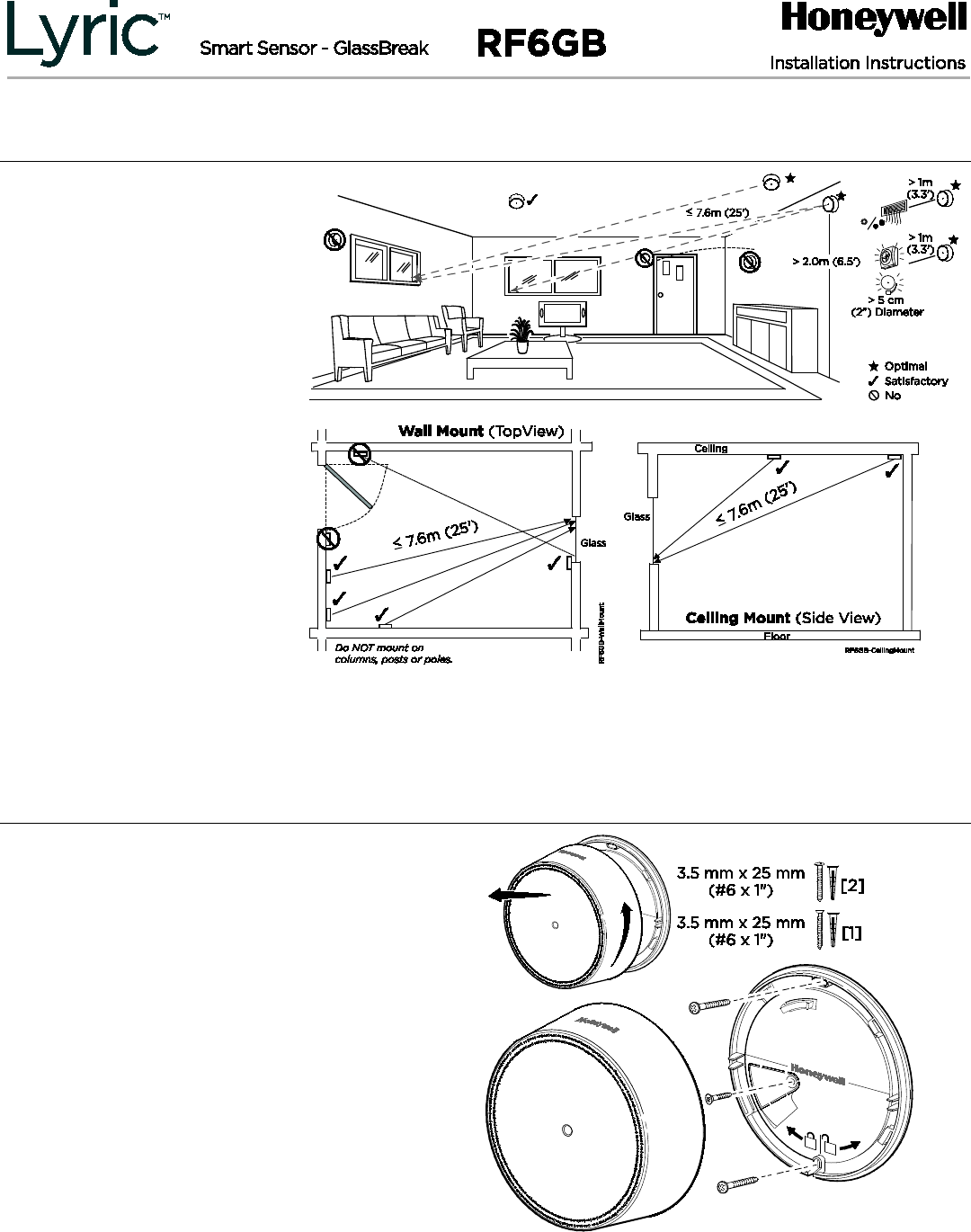
Mounting
The RF6GB can be mounted
on the wall or on the ceiling.
• within 7.6 m (25 feet) of the
protected glass;
• within clear view of the
protected glass;
• at least 2 m (6.5 feet) from the
floor;
• at least 1 m (3.3 feet) from
forced air ducts;
• at least 1 m (3.3 feet) from
sirens or bells greater than 5
cm (2 inches) in diameter.
• between the protected glass
and any heavy window
coverings.
• when heavy window coverings
are present, the detector can
be mounted on the window
frame.
• Avoid mounting the detector
on the same wall as the
protected glass, on free-
standing posts or pillars, or in
rooms with noisy equipment
(air compressors, bells, power
tools, etc.), if this equipment is
operated when the detector is
armed.
• UL requirements: TBD
To remove the mounting bracket:
Turn the top of the detector 15 degrees
counter-clockwise and separate the
mounting bracket.
Note
: Before mounting the RF6GB
permanently, conduct Go/No Go tests (see
control’s instructions) to verify adequate
signal strength and adjust the device location
and orientation as necessary.
• The RF6GB can be mounted on the wall
or on the ceiling.
• The rear tamper plate MUST be mounted
to a stud, solid wood, or with a robust
wall anchor.
BETA DRAFT – 01/12/15
PLEASE GO TO THE LAST PAGE FOR FCC/IC
AGENCY STATEMENTS
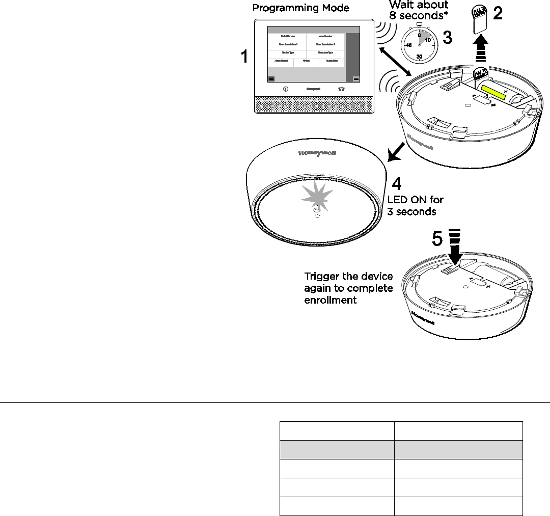
Enroll
This device can be enrolled and
programmed either before or after
installation.
1. Set the Lyric Smart Controller in
Programming Mode.
2. Remove the battery tab to activate the
device and begin the enrollment
process.
3. The RF6GB Green LED flashes during
enrollment (about 8 seconds*)
*Note
: Depending on the signal strength
between the device and the control, the
enrollment period may take longer than 8
seconds.
• The device sends its unique MAC ID
address (Serial Number) and Services
information to the control.
• The control registers the device and
displays the transmitter data on
screen.
4. Enrollment is confirmed When the
RF6GB Green LED is ON for 3 seconds
[and the control beeps TBD].
5. If the sensor is not successfully enrolled
during the enrollment period, the LED
turns off and the device powers down.
Activate the tamper, power down and
up again, or use the FG701 Glassbreak
Simulator to restart the enrollment
process.
Note
: Once enrolled in a system, the detector cannot be used with
another control panel until it is removed from the current control
panel. See the Control’s instructions for details on removing
devices.
Program the RF6GB
Consult the Control’s instructions for
programming the device in the system.
Fault device features to “Learn” device
“Services” in the control:
- Tamper switch
- Selectable Sensitivity Settings
- Temperature sensing
Temperature Sensing
Temperature sensing range is 0 – 50°C /
32 – 122°F and is always enabled. Program the
system to use the temperature information at
the panel.
Sensitivity Setting
Approximate Range
High 4.6-7.6m / 15-25 ft.
Medium 3-4.6m / 10-15 ft.
Low 1.5-3m / 5-10 ft.
Lowest 0-1.5m / 0-5 ft.
The RF6GB detector is Factory set at HIGH
sensitivity. Change the sensitivity setting at
the Control Panel.
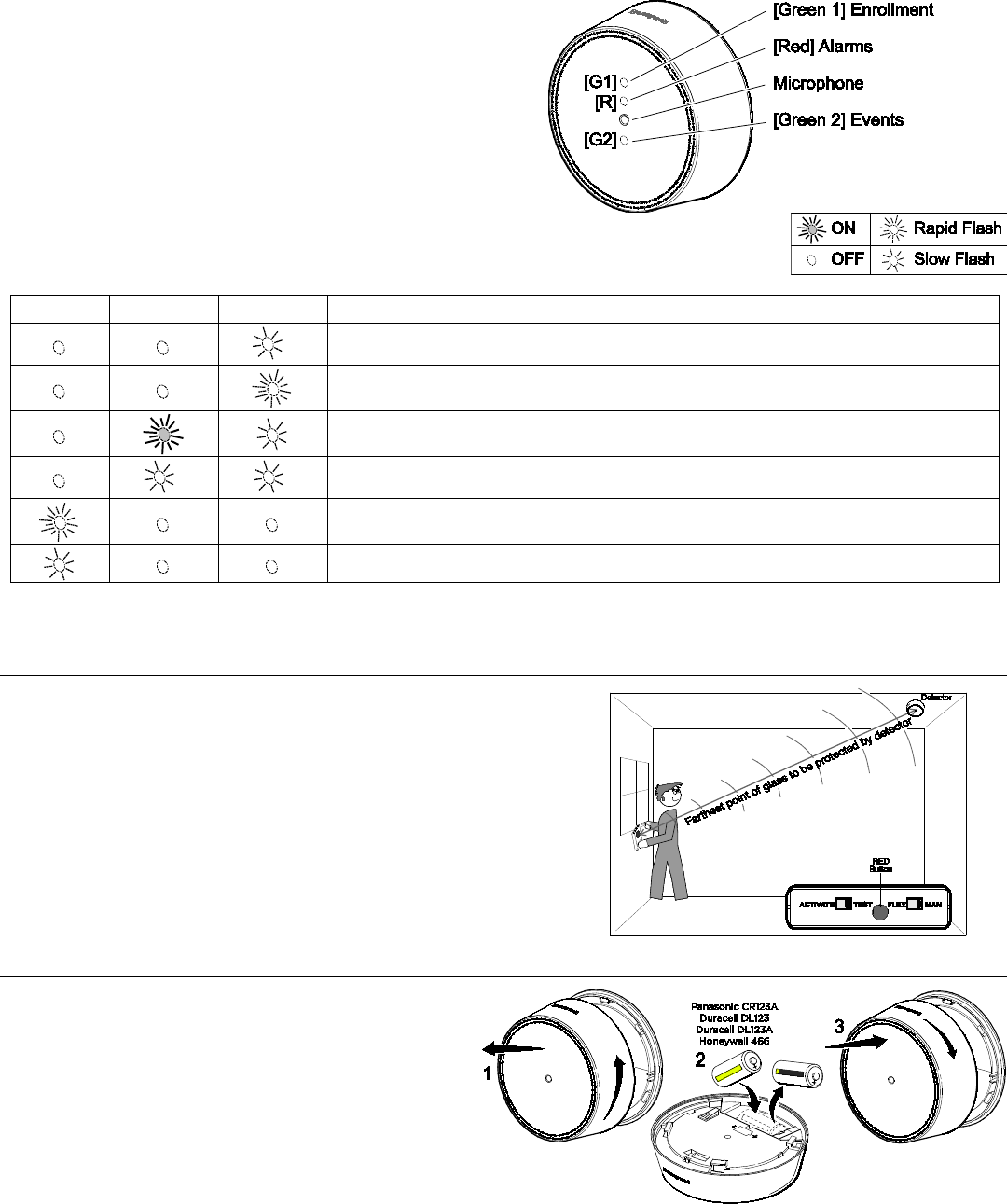
RF6GB LEDs
The RF6GB has three LEDs which are visible
when the unit is mounted.
Green 1 LED indicates device enrollment and
tamper status.
The Red and Green 2 LEDs provide information
on detector status during Test Mode. The Green
2 LED indicates events and the Red LED
indicates Alarms.
LED Indications Table
G1
Red
G2
Status
1 Test Mode2
Event detected during Test Mode
Alarm detected during Test Mode
3 3 Low Battery detected during Test Mode
Power Up / Tamper switch pressed / FG-701 Activated before enrollment
Tamper Detected
1 If RF6GB Test Mode is activated by the FG701, the Green 2 LED will flicker, then be off for 3 seconds, then flash once per second.
2 Test Mode lasts for 10 minutes.
3 This feature is used for field diagnosis. The LEDs are not visible during Normal Mode to save power.
Test the RF6GB
The RF6GB should be tested after installation and at least
once a year.
Test Mode can be activated remotely from the Control
Panel (see Control Panel manual), or on-site with an FG-
701 Glassbreak Simulator, only when the system is
disarmed
.
Follow directions in the FG-701 Glassbreak Simulator
Operating Instructions to activate and test the RF6GB
detector.
Battery Replacement
• Twist the front cover counterclockwise 15
degrees and separate from the mounting
bracket.
• Remove and replace the battery.
Recommended replacement batteries:
Panasonic CR123A Honeywell 466
Duracell DL123 Duracell DL123A
• Reattach the front cover and twist it 15
degrees clockwise to lock it in place.
BATTERY CAUTION
: Risk of fire, explosion and burns.
Do not recharge, disassemble, heat above 100° C (212° F)
or incinerate. Dispose of used batteries promptly. Keep
away from children.
Specifications
Battery
: Panasonic CR123A, Duracell DL 123, Duracell DL 123A, Honeywell 466
Tamper
: Cover and Wall
RF Frequency
: 2.4GHz
Operating Temperature
: 0° to 50° C / 32° to 122° F
Relative Humidity
: 5 – 95%, non-condensing
Dimensions: 96 mm Diameter x 29mm Thick / 3.78” Diameter x 1.14” Thick
Approval Listings
RoHS
FCC / IC
ULC S306-03
UL 639
Protected Glass Types Chart [PRELIMINARY – TBD AFTER AGENCY TESTING]
NOTE: The RF6GB is NOT recommended for protection of glass areas smaller than 27.6 cm x 27.6 cm (10-7/8 inches x 10-7/8 inches).
Glass Type*
Nominal Thickness
Minimum
Maximum
Plate
2mm (3/32 in.)
10mm (3/8 in.)
Tempered
3mm (1/8 in.)
10mm (3/8 in.)
Laminated1, 3
3mm (1/8 in.)
14mm (9/16 in.)
Wired
6mm (1/4 in.)
6mm (1/4 in.)
Coated2, 3
3mm (1/8 in.)
6mm (1/4 in.)
Sealed Insulating1,3
3mm (1/8 in.) [13mm (1/2 in.) overall]
6mm (1/4 in.) [19mm (3/4 in.) overall]
* Minimum size for all types is 28cm (11 in.) square; glass must be framed in the wall or mounted in a barrier at least 0.9m
(36 in.) wide.
1 Protected only if both plates in the unit are broken
2 Coated glass with security films up to 0.35mm (14 mils) thick (including films for solar protection) may be used. Evaluated with the these products:
3M® SCOTCHSHIELD® SH14CLARL – 0.35mm (14 mils), 4 ply film; Film Technologies International, Inc.’s GLASS-GARD GGLL 1200 has been evaluated
with this product by Underwriters Laboratories, Inc.
3 In compliance with Underwriters Laboratories of Canada’s Standard for Intrusion Detection Units (CAN/ULC-S306-M89):
a. Plate glass 3mm (1/8-in.) to 10mm (3/8-in.) can be used.
b. ULC recognizes a maximum range for protecting sealed insulating glass, 1/8” laminated and coated glass of 3.8m (12.5 ft.); sensitivity should be set
to High.
FEDERAL COMMUNICATIONS COMMISSION & INDUSTRY CANADA STATEMENTS
The user shall not make any changes or modifications to the equipment unless authorized by the Installation Instructions or User's Manual. Unauthorized
changes or modifications could void the user's authority to operate the equipment.
FCC / IC STATEMENT
This device complies with Part 15 of the FCC Rules, and RSS-210 of Industry Canada. Operation is subject to the following two conditions: (1) This device
may not cause harmful interference, and (2) This device must accept any interference received, including interference that may cause undesired operation.
Cet appareil est conforme à la partie 15 des règles de la FCC & de RSS-210 des Industries Canada. Son fonctionnement est soumis aux conditions suivantes:
(1) Cet appareil ne doit pas causer d’interférences nuisibles. (2) Cet appareil doit accepter toute interférence reçue y compris les interférences causant une
reception indésirable.
RF Exposure
Warning – The antenna(s) used for this device must be installed to provide a separation distance of at least 7.8 inches (20 cm) from all persons and must
not be co-located or operating in conjunction with any other antenna or transmitter except in accordance with FCC multi-transmitter product procedures.
Mise en Garde
Exposition aux Frequences Radio: L'antenne (s) utilisée pour cet émetteur doit être installée à une distance de séparation d'au moins 7,8 pouces
(20 cm) de toutes les personnes.
Support and Warranty
REFER TO THE INSTALLATION INSTRUCTIONS FOR THE CONTROL WITH WHICH THIS DEVICE IS USED, FOR DETAILS REGARDING LIMITATIONS OF
THE ENTIRE ALARM SYSTEM.
For the latest U.S. warranty information, please go to www.honeywell.com/security/hsc/resources/wa or
Please contact your local authorized Honeywell representative for product warranty information.
2014 Honeywell International Inc. Honeywell and is a registered trademark of Honeywell International Inc.
All other trademarks are the properties of their respective owners. All rights reserved.
DOC CODE 128B BAR CODE HERE
P/N 800-19202GB 01/15 Rev BETA
2 Corporate Center Drive, Suite 100
P.O. Box 9040, Melville, NY 11747
www.honeywell.com/security