Ademco 8DLLYNXPLUS2 Wireless Control / Communicator User Manual 800 03857 ii
Honeywell International Inc. Wireless Control / Communicator 800 03857 ii
Ademco >
Contents
- 1. Users Manual Lynx Plus
- 2. English Supplement
- 3. Important Information
Users Manual Lynx Plus
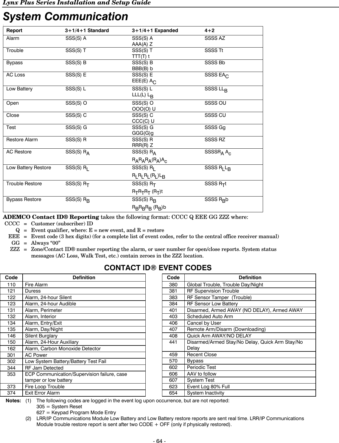
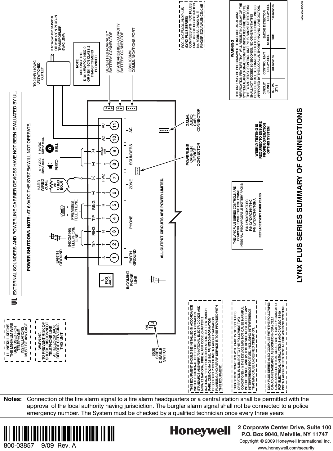
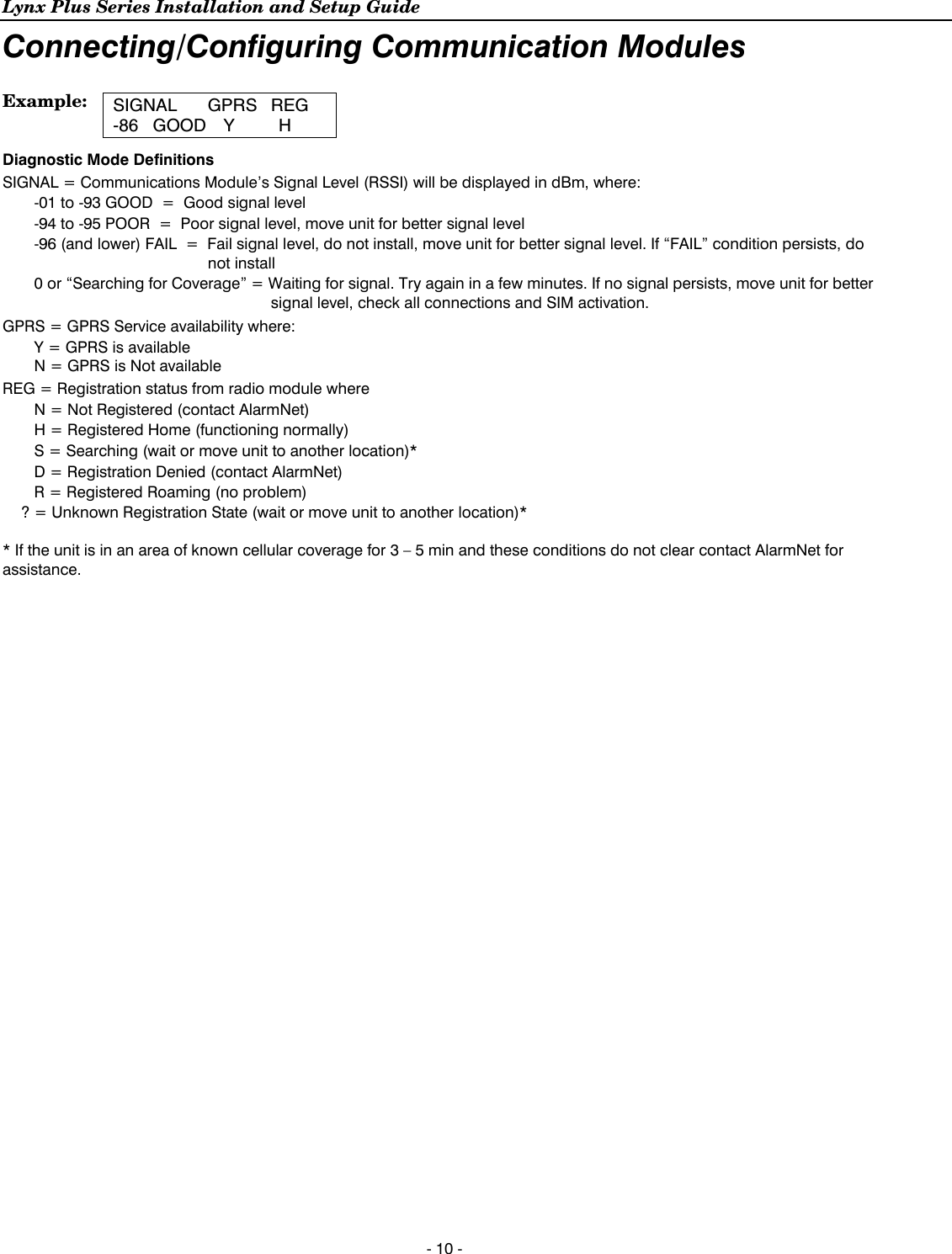
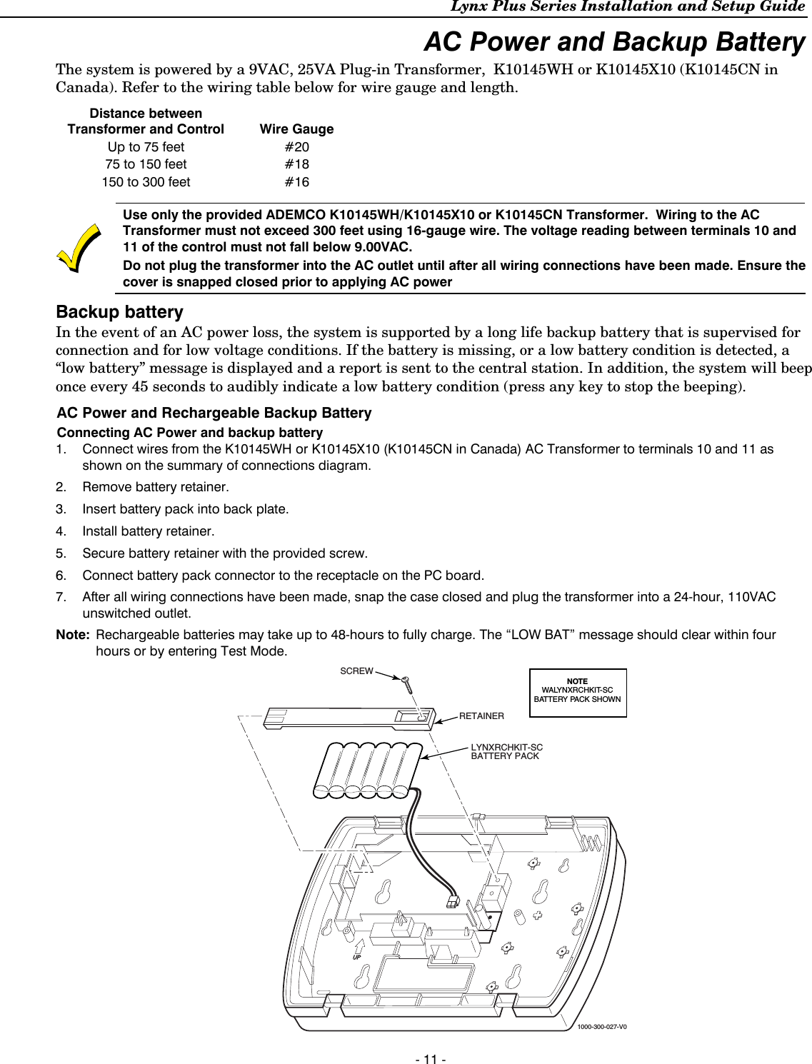
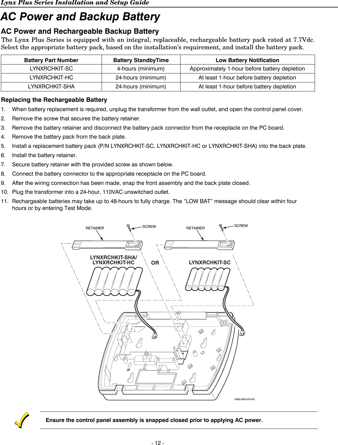
![Lynx Plus Series Installation and Setup Guide - 9 - Connecting/Configuring Communication Modules General This Lynx Plus Series control supports central station reporting via the internet using wireless (GSM) and hardwire (IP) communications modules. It also supports upload/download programming capability via the Internet or a Private local area network (Intranet). This allows site maintenance independent of central station monitoring, and modification to sites globally via the Internet or through a private LAN. Refer to the instructions provided with the LRR/IP Communications Device being installed for additional information regarding its installation, programming, and registration. The control is compatible with the following AlarmNet Communications Modules: • 7847i-L Internet Communications Module • GSMVLP GSM Communications Module with 2-Way Voice Connecting Long Range Radio and Internet Communication Devices Connect and configure the communications device (refer to the Installation Instructions for device that you are installing for additional information). LRR/IP Communications Device 24-Hour Standby Power If you are installing the AlarmNet 7847i-L, and require 24-hour standby, you must install the Super High Capacity battery P/N WALYNX-RCHB-SHA in the control. Configuring Long Range Radio and Internet Communication Devices 1. Enable the communications device in programming field ✼55 and configure alarm reporting and module supervision in programming field ✼77. 2. Program the device as required using the 7720P programmer (refer to the Installation Instruction for the device that you are installing). Note that the device address must be set to 3. The device must be registered before downloading or alarm reporting can take place. LRR Communications Device Diagnostic ModeThis mode provides a method to verify the LRR signal strength. 1. Enter the Installer Code (4112) + 899. The system will initially display “Entering programming mode”. 2. The LRR Communications Module’s Signal Level (Primary Site Received Signal Strength Indication [PriRSSI]) will be displayed in dBm. The system will also display GPRS connection and registration indications (refer to the example that follows). 3. If “FAIL” or “POOR” signal levels are displayed during the test, the control should be relocated to find a location that provides better signal strength. If a ‘searching for coverage’ message is displayed or the radio is not connected and no signal indication is displayed, the installer should check radio programming, panel programming, etc., before entering this mode again. Signal strength may vary 4. The Lynx Plus will automatically exit this mode after approximately 1-minute or if any key is pressed. The system will display “Exiting programming mode” when the test is complete.](https://usermanual.wiki/Ademco/8DLLYNXPLUS2.Users-Manual-Lynx-Plus/User-Guide-2014867-Page-8.png)
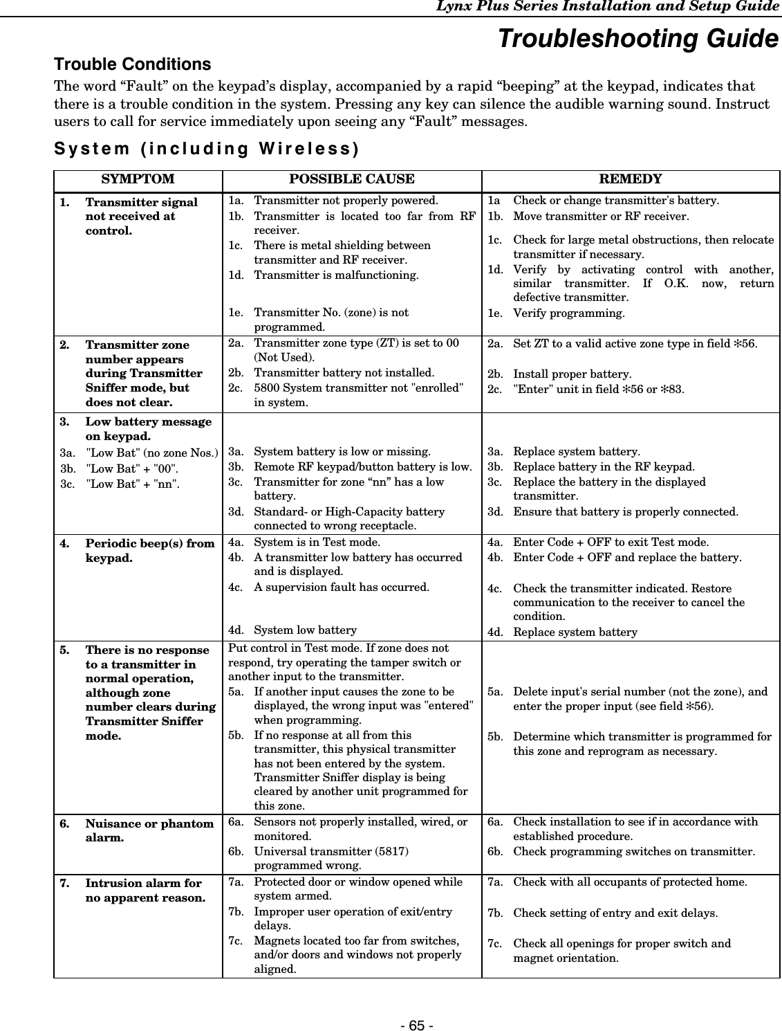
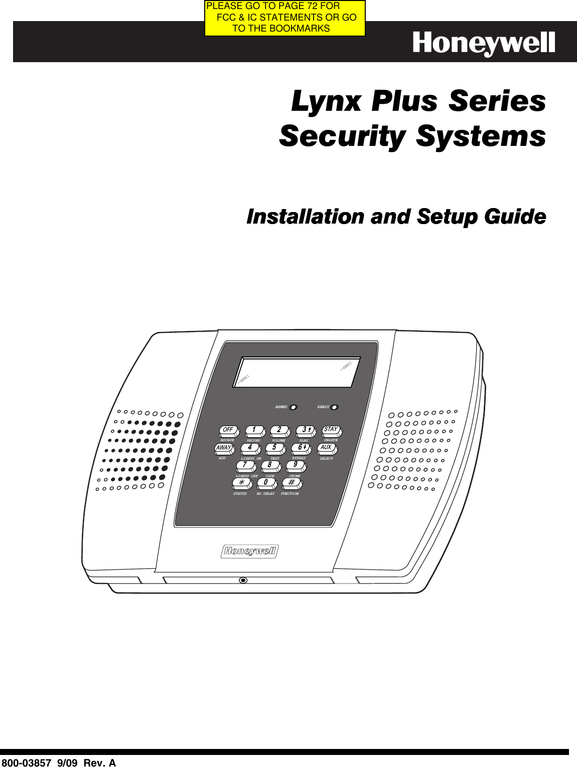
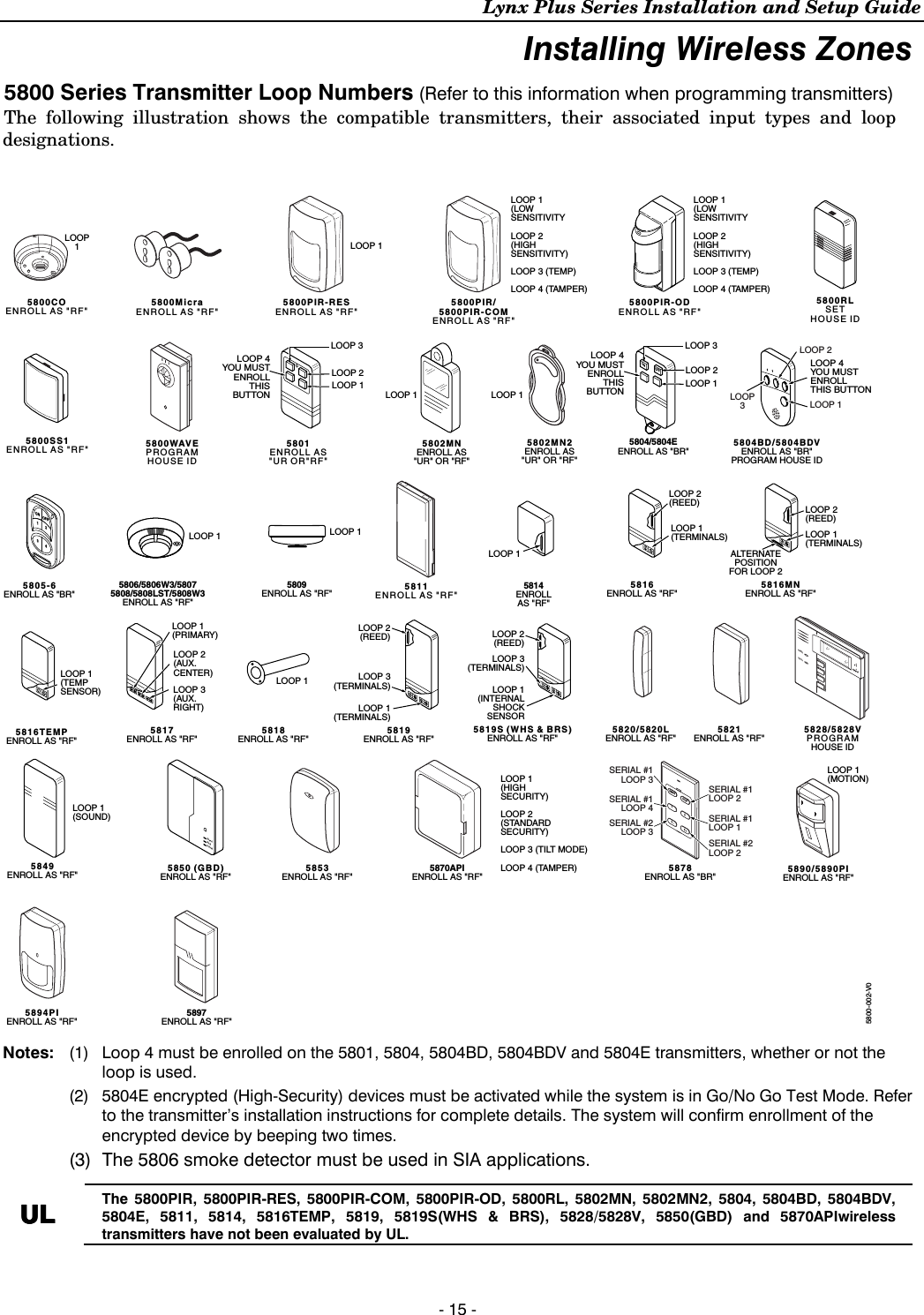
![Lynx Plus Series Installation and Setup Guide - 14 - Installing Wireless Zones • Button-type transmitters should be periodically tested for battery life. The 5801, 5802MN, 5802MN2, 5804, 5804BD, 5804BDV, and 5804E button transmitters have replaceable batteries. Using the Transmitter Sniffer Mode Use this mode after all transmitters have been entered to check that all transmitters have been properly programmed. 1. Enter Installer code (4112) + [#] + 3. Note: If the communicator is in the process of sending a report to the central station, the system will not go into the Sniffer mode. If so, wait a few minutes and try again. 2. The keypad will display all zone numbers, which have a non-zero Zone Type (even if serial numbers were not learned yet). Fault each transmitter in turn, causing each one to send a signal. As the system receives a signal from each of the transmitters, the zone number of that transmitter will disappear from the display. The transmitters may be checked upon installation, or in an installed system. 3. When all transmitters have been checked, exit Sniffer mode. Enter Installer Code (4112) + OFF. Notes: (1) Sniffer mode does not automatically expire. You must manually exit (Installer Code + OFF) Sniffer mode to return to normal operation. (2) All BR-type units must physically be activated to clear the display, since they do not automatically send check-in signals. (3) When one button of a transmitter (RF, UR, or BR) is activated, all zones assigned to other buttons on that transmitter are cleared. This also applies to 5816 and 5817 transmitters that have multiple loops (zones). (4) Any transmitter that is not “entered” will not turn off its zone number. (5) For SIA installations, the following devices may be used as specified for panic (24-hour) alarm response: • wireless keys which have two-button panic pairs available (e.g., 5804BDV), on which only the two-button panic pairs may be programmed for any 24-hour alarm response • wireless keypads (e.g., 5828/5828V) keypads that have a two-second delay on the special function keys, or two-button panic pairs • built-in keypad’s two-button panic pairs Go/No Go Test Mode 5804E encrypted (High-Security) devices must be activated while the system is in Go/No Go Test Mode. Refer to the transmitter’s installation instructions for complete details. The system will confirm enrollment of the encrypted device by beeping two times The Go/No Go tests will verify adequate RF signal strength from the proposed transmitter location, and allow you to reorient or relocate transmitters if necessary, before mounting the transmitters permanently. This mode is similar to the transmitter Test mode, except that the wireless receiver gain is reduced. This will enable you to make sure that the RF signal from each transmitter is received with sufficient signal amplitude when the system is in the normal operating mode. 1. Enter Installer Code (4112) + [#] + 8. 2. Once you have placed transmitters in their desired locations and the approximate length of wire to be run to sensors is connected to the transmitter's screw terminals (if used), fault each transmitter. Conducting this test with your hand wrapped around the transmitter will cause inaccurate results. On button type transmitters that have been programmed to set ARM AWAY, ARM STAY, or DISARM, press-ing a button will take the system out of the Go/No Go Test mode causing the programmed action to occur. Note: On button type transmitters that have been programmed to set ARM AWAY, ARM STAY, or DISARM, pressing a button will take the system out of the Go/No Go Test mode and cause the programmed action to occur. a. The keypad will beep three times indicating signal reception and will display the appropriate zone number. b. If the keypad does not beep, reorient or move the transmitter to another location. Usually a few inches in either direction is all that is required. 3. If each transmitter produces the proper keypad response when it is faulted, you can then permanently mount each of the transmitters according to the instructions provided with them. 4. Exit the Go/No Go Test mode by entering: Installer Code (4112) + OFF.](https://usermanual.wiki/Ademco/8DLLYNXPLUS2.Users-Manual-Lynx-Plus/User-Guide-2014867-Page-13.png)
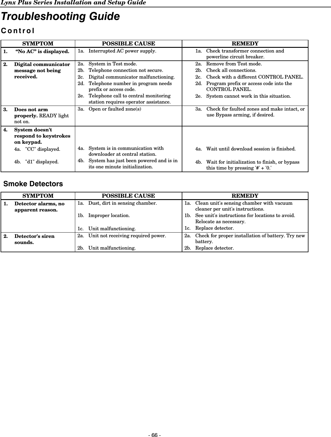
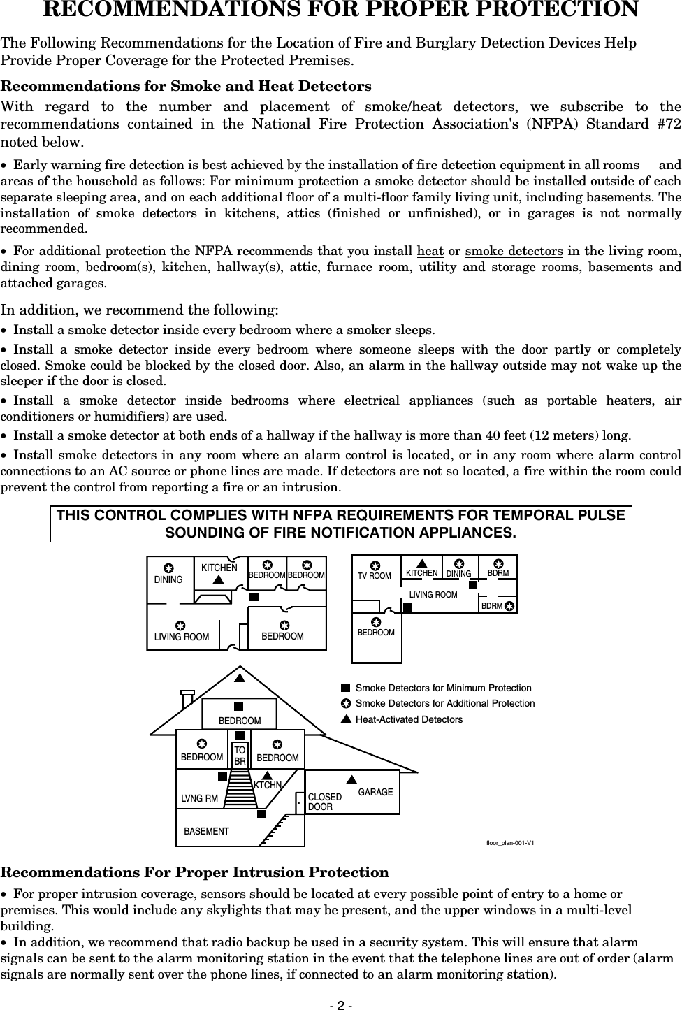
![Lynx Plus Series Installation and Setup Guide - 16 - Mechanics of Programming General Programming Information Programming options are stored in non-removable, electrically erasable, nonvolatile EEROM memory. The system can be programmed at any time, even at the installer's premises prior to the actual installation. Simply apply power temporarily to the Control and then program the unit as desired. There are four programming modes: • Data field programming (used for setting various system options). • Interactive menu mode programming (used for programming zone information, programming Powerline Carrier Devices, and for entering transmitter serial numbers). • Voice Prompt programming (used for setting various system options). The system can also be programmed remotely, using an IBM PC compatible Personal Computer, and Compass Downloader and modem or via capable GSM or IP communications modules. See the Remote Programming/Control (Downloading) section. Note: You may find it convenient to adjust the volume setting before entering the Program Mode. This will allow you to clearly hear the feedback announcements or system beeps in the Programming Mode, of the system’s built-in speaker. To adjust the volume, press FUNCTION + VOLUME+ [3] or [6]. Upon exiting the Program Mode, the system will reset the volume to the default value (mid level). Entering Program Mode Use one of the following methods to enter Programming Mode: 1. Press both the [✻] and [#] keys at the same time, within 50 seconds after power is applied to the Control or from exiting Programming mode, OR 2. After power-up, enter the Installer Code (4112) + 800 to enter Expert Programming mode OR enter Installer Code (4112) + 888 to enter Voice Prompt Programming mode. This method is disabled if Program mode is exited using ✻98. If a different Installer Code has been programmed, use that code to enter the Programming mode. 3. Upon entering programming mode, the control will initially display “Entering Programming Mode”. 4. Once you have entered the Program mode, data field “20 INSTALLER CODE” (the first data field in the system) will be displayed and both keypad LEDs will flash. If you have entered the Voice Prompt Programming mode. “Pro” will be displayed and the system will announce “Programming, use arrows to scroll choices. Press select to accept, press escape to quit”. Programming a Data Field 1. Press [✻] + Field No. (for example, ✻21), followed by the required entry. 2. When you have completely programmed a data field, the keypad will “beep” three times and then automatically display the next data field in sequence. To go to a different field, press [✻] plus the desired field number. 3. If the number of digits that will be entered in a data field is less than the maximum number of digits available (e.g. phone number field), enter the desired data, then press [✻] to advance to the next data field. 4. If a nonexistent field has been entered, the keypad will display “EE Invalid Entry”. Simply re-enter [✻] plus a valid field number. Viewing a data field (without making changes): Enter [#] + Field No. The system will beep three times and data programmed for that field will be displayed to the right of the field number. The system will scroll through the data for longer numbers and a beep will sound after each number is displayed or three times after the final digit is displayed. Deleting an entry in a field Enter [✻] + Field No. + [✻]. (Applies only to fields ✻40–✻44, ✻88 and ✻94).](https://usermanual.wiki/Ademco/8DLLYNXPLUS2.Users-Manual-Lynx-Plus/User-Guide-2014867-Page-15.png)
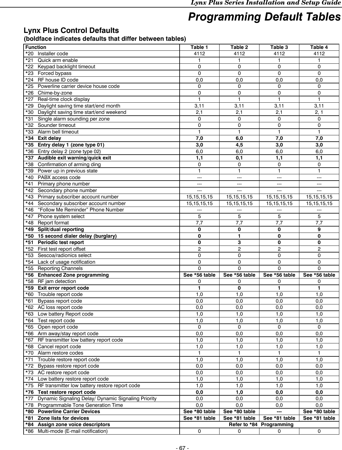
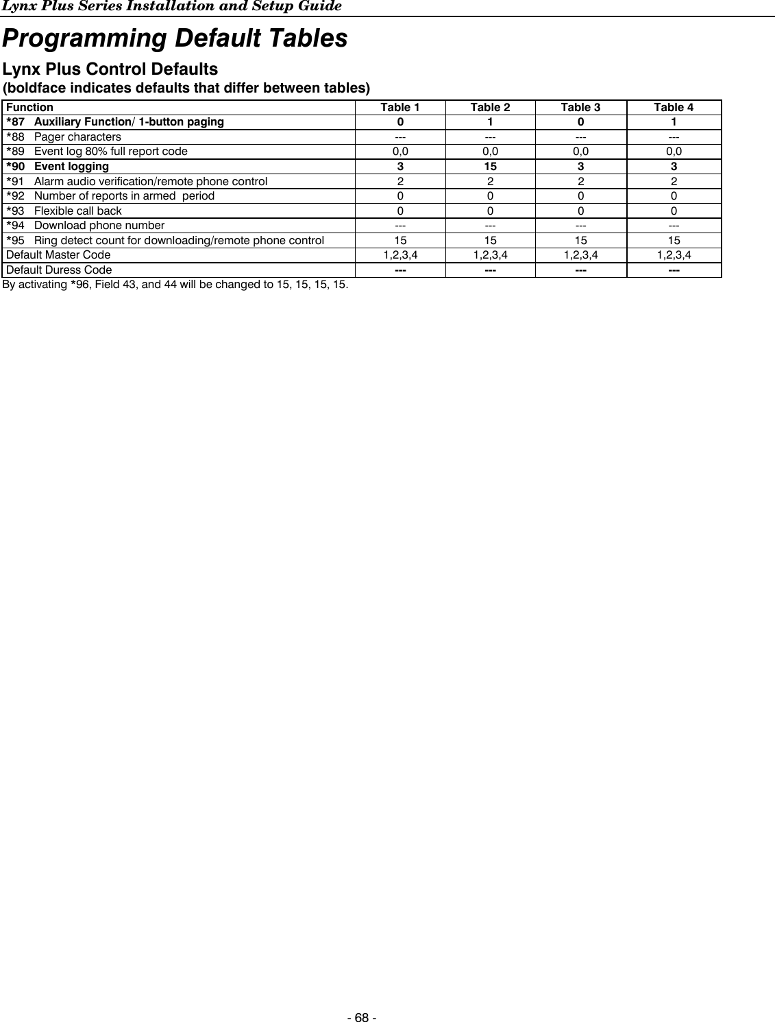
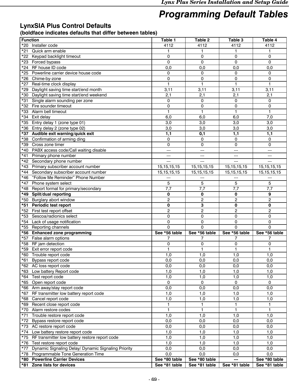
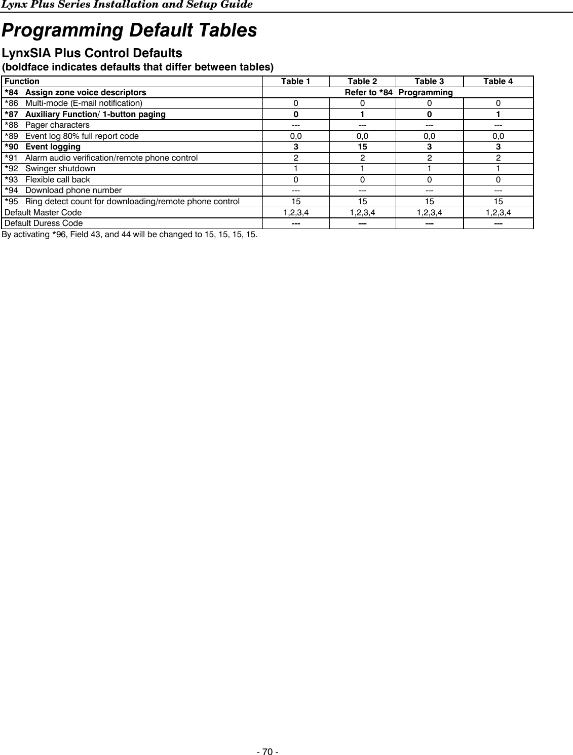
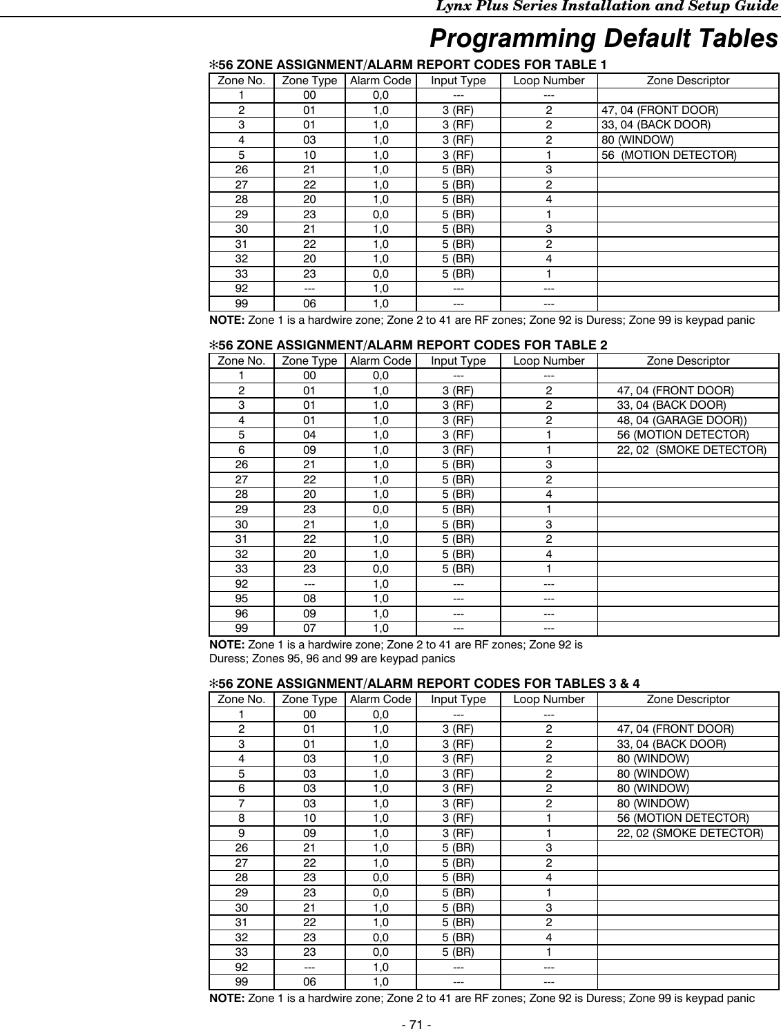
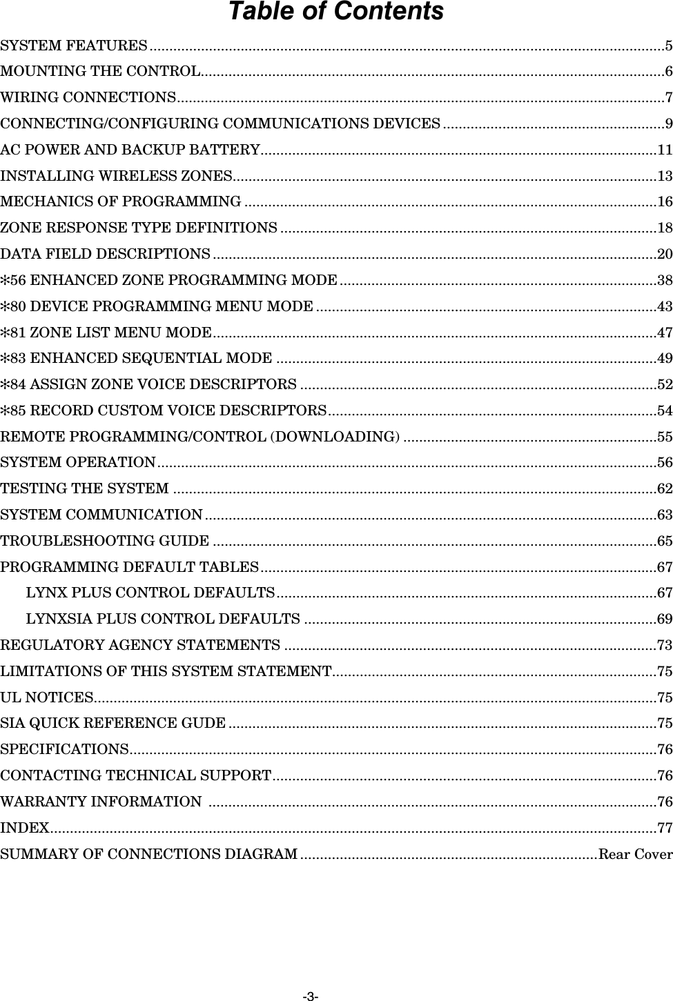
![Lynx Plus Series Installation and Setup Guide - 17 - Mechanics of Programming Interactive Menu Mode Programming (✻56, ✻80, ✻81, ✻83, ✻84, ✻85) Press [✻] + interactive mode No. (i.e., ✻56). The keypad will display the first of a series of prompts. A detailed procedure (with displays of prompts) is provided in later sections of this manual. ✻56 Enhanced Zone Programming Mode Interactive menu mode used for programming zone attributes and report codes. Refer to the ✻56 Enhanced Zone Programming Mode section for procedure. ✻80 Device Programming Menu Mode Interactive menu mode for programming Powerline Carrier Devices. Refer to the ✻80 Device Programming Menu Mode section for detailed procedure. ✻81 Zone Lists Menu Mode Interactive menu mode for programming zone lists for Powerline Carrier Devices. Refer to the ✻81 Zone List Menu Mode section for detailed procedure. ✻83 Enhanced Sequential Mode Interactive menu mode used to enter RF transmitter serial numbers. Refer to the ✻83 Enhanced Sequential Mode section for detailed procedure. ✻84 Assign Zone Voice Descriptors Interactive menu mode used to assign descriptors to each zone. These descriptors will be announced whenever the system announces an event involving a zone. ✻85 Record Custom Voice Descriptors Interactive menu mode used to record custom descriptors for use with each zone. ✻96 Initialize Download ID and Subscriber Account Number for Downloading Entering ✻96 resets all subscriber account numbers and CSID in preparation for an initial download. Loading Factory Defaults ✻97 To load the factory defaults, enter ✻97, then press number 1, 2, 3, or 4 to select from default tables 1-4, or press “0” if you are not selecting a default table. Refer to the Programming Default Tables section of this manual to view the tables. If a default table is loaded, any data that has already been programmed into the system will be changed according to the default table selected! Exiting Program Mode ✻98 Exits program mode and inhibits re-entry into the Expert or Voice Prompt Programming modes using the Installer Code. ✻99 Exits program mode but allows re-entry into the Expert Program mode using Installer Code (4112) + 800 or into the Voice Prompt Programming mode using Installer Code (4112) + 888. Note: After exiting program mode (or upon power-up), the system takes up to a minute to reset. To bypass the reset delay, press [#] + [0].](https://usermanual.wiki/Ademco/8DLLYNXPLUS2.Users-Manual-Lynx-Plus/User-Guide-2014867-Page-16.png)
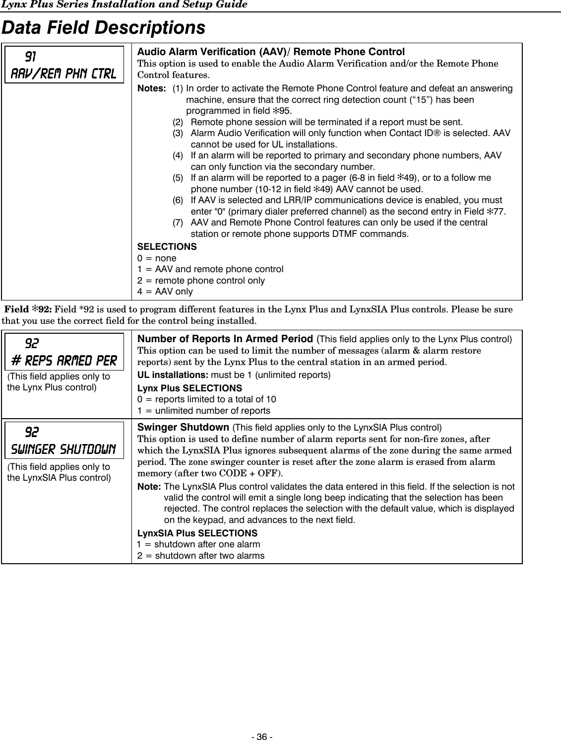
![Lynx Plus Series Installation and Setup Guide - 24 - Data Field Descriptions 39393939 CROSS CROSS CROSS CROSS ZONE ZONE ZONE ZONE TIMERTIMERTIMERTIMER (This field applies only to the LynxSIA Plus control) Cross Zone Timer (This field applies only to the LynxSIA Plus control) Sets the maximum amount of time in which two cross zones must be tripped in an armed system to send an alarm message to the Central Station. If only one cross zone is tripped during this time, a trouble message (CID code 380) for that zone is sent to the Central Station. Program Zone list 2 (using *81 Zone List Menu Mode) with the two zones that are to be cross zoned. Notes: (1) If option ✻39 is set to “0” (no cross zoning), Zone List 2 can be used for other purposes. (2) Cross zoning will be disabled during entry and exit delays, if one or both of the 2 cross zones is bypassed and there is already an alarm in the system. If one of the 2 cross zones faults and remains faulted after the cross zone time interval, the second cross zone can go into alarm immediately, even after the cross zone time. This is to detect scenarios involving multiple break-ins of a premises. UL This option is not for use in UL installations. LynxSIA Plus SELECTIONS Value Time Window Value Time Window 0 = No Cross Zoning 8 = 2 minutes 1 = 15 seconds 9 = 2 minute, 15 seconds 2 = 30 seconds # + 10 = 2 minute, 30 seconds 3 = 45 seconds # + 11 = 2 minute, 45 seconds 4 = 60 seconds # + 12 = 3 minutes 5 = 1 minute, 15 seconds # + 13 = 3 minute, 15 seconds 6 = 1 minute, 30 seconds # + 14 = 3 minute, 30 seconds 7 = 1 minute, 45 seconds # + 15 = 3 minute, 45 seconds DIALER PROGRAMMING (✻40–✻50) Fields ✻40, ✻41, ✻42: Enter up to the number of digits shown. Enter 0–9, # + 11 for ‘✻’; # + 12 for ‘#’; # + 13 for a pause (2 seconds). Field ✻40 is used to program different features in the Lynx Plus and LynxSIA Plus controls. Please be sure that you use the correct field for the control being installed. Notes: Whenever AAV is used, primary (Field ✻41) and secondary (Field ✻42) phone numbers should be preceded with the call waiting disable command. Otherwise, there is the possibility of connection of the third party to Lynx Plus Series during AAV mode. The PABX phone number entered in field ✻40 is not dialed on GSM/IP (Digital Communication with AAV). However, it is used for dialing on Telco Line. 40 40 40 40 PABX PABX PABX PABX ACCESS ACCESS ACCESS ACCESS CODECODECODECODE (This field applies only to the Lynx Plus control) PABX Access Code (This field applies only to the Lynx Plus control.) If fewer than 6 digits will be entered, exit by pressing [✻]. To clear entries, press ✻40✻. Lynx Plus SELECTIONS PABX Access Code Enter up to 6 digits if PABX is needed to access an outside line. 40404040 PABX PABX PABX PABX ACCESS CODE ACCESS CODE ACCESS CODE ACCESS CODE (This field applies only to the LynxSIA Plus control) PABX Access Code/Call Waiting Disable (This field applies only to the LynxSIA Plus control) If fewer than 6 digits need to be entered, exit by pressing [✻]. To clear entries from field, press ✻40✻. If the subscriber does not have “call waiting” and is not using PABX, make no entry in this field. Call Waiting: If the subscriber’s phone service has “call waiting” (and is not using PABX), enter the touch-tone sequence“✻70” (or similar depending on the phone service). By programming “# + 11 + 7 + 0” as the PABX entry to disable “call waiting” during control panel calls. You must also enable the Call Waiting Cancel option in field ✻47. Important Note: If Call Wait Cancel is disabled in Field ✻47, and Call Wait Disable command is entered in Field ✻40, this will prevent successful communication to the central station when used on a non-call waiting line. Note: PABX number and operation of the control panel with a PBX system cannot be used if the Call Waiting Cancel Disable option has been enabled in Field ✻47. LynxSIA Plus SELECTIONS PABX Access Code/Call Waiting Disable Enter up to 6 digits if PABX is needed to access an outside line. OR Enter“# + 11+ 7+ 0” to program touch-tone sequence “✻70” and cancel call waiting.](https://usermanual.wiki/Ademco/8DLLYNXPLUS2.Users-Manual-Lynx-Plus/User-Guide-2014867-Page-23.png)
![Lynx Plus Series Installation and Setup Guide - 25 - Data Field Descriptions If the LRR/IP (Digital Communication with AAV) feature is used (options 5 in ✻55), there may be restrictions when dialing the numbers entered in ✻41, ✻42 and ✻46 (i.e.; #, ✻, pause may not be allowed, or phone number extensions may not be dialed, etc) depending on the service provider. 41 41 41 41 PRIMARY PRIMARY PRIMARY PRIMARY TEL TEL TEL TEL NUM NUM NUM NUM Primary Phone Number Enter the Primary Phone Number If fewer than 20 digits entered, exit by pressing [✻]. To clear entries from field, press ✻41✻. Note: Backup reporting (8 attempts are made to the secondary phone number if no kissoff is received after 8 attempts to the primary number) is automatic only if there is a secondary phone number (field ✻42). SELECTIONS Enter up to 20 digits. 42 42 42 42 SECOND SECOND SECOND SECOND TEL TEL TEL TEL NUMNUMNUMNUM Secondary Phone Number Enter the Primary Phone Number If fewer than 24 digits entered, exit by pressing [✻]. To clear entries from field, press ✻42✻. See backup reporting note for field ✻41. SELECTIONS Enter up to 24 digits. All four digits of the Subscriber Account number must be entered in Fields ✻43 and ✻44. If ten-digit format is selected in ✻48 (option 5), all ten digits of the Subscriber Account number must be entered. Fields ✻43 and ✻44: Enter [✻] as the fourth digit if a 3-digit account number (for 3+1 dialer reporting format) is used. Enter 0 as the first digit of a 4-digit account number for Nos. 0000–0999. Enter [✻] as the fifth digit if a 4-digit account number (for 4+1, 4+2 CID®) is used. Exit field by pressing [✻] if only 3 digits are used. See blank Programming Form for examples of account number entries. Enter digits 0–9; # +11=B; # +12=C; # +13=D; # +14=E; or # +15=F. 43434343 PRIMARYPRIMARYPRIMARYPRIMARY ACCACCACCACCOUNOUNOUNOUNTTTT# Primary Subscriber Account Number Enter the primary subscriber account number. To clear entries from field, press ✻43✻. SELECTIONS Enter a 4 or 10- digit account number 44 44 44 44 SECNDRY SECNDRY SECNDRY SECNDRY ACCOUNTACCOUNTACCOUNTACCOUNT# Secondary Subscriber Account Number Enter the primary subscriber account number. To clear entries from field, press ✻44✻. SELECTIONS Enter a 4 or 10- digit account number Field ✻46: Enter up to 24 digits. Do not fill unused spaces. Enter 0-9, #+11 for ‘✻’; #+12 for’#’; #+13 for a pause (2 seconds). 46 46 46 46 FOLLOWFOLLOWFOLLOWFOLLOW ME ME ME ME PHONEPHONEPHONEPHONE# “Follow Me Reminder” Phone Number This option allows the user to schedule a time driven message. When activated the system will dial the phone number programmed and deliver a voice message (custom words 72, 73 and 74). This option is only supported when the follow me feature is enabled in field ✻49 (option 6-9 or 10-13). If using the Follow Me Reminder feature, enter the phone number here. If fewer than 24 digits are entered, exit by pressing [✻]. To clear entries from the field press ✻46✻. The telephone message can be terminated (acknowledged) by pressing any key on the telephone keypad. Pressing any key on the local Lynx Plus Series keypad will terminate (acknowledge) both the follow me and the local reminder announcements. Note: The follow me reminder announcement will be terminated if any other event requires the system to dial out or if an audible alarm has occurred. SELECTIONS Enter up to 24 digits.](https://usermanual.wiki/Ademco/8DLLYNXPLUS2.Users-Manual-Lynx-Plus/User-Guide-2014867-Page-24.png)
![Lynx Plus Series Installation and Setup Guide - 35 - Data Field Descriptions 87878787 AUX AUX AUX AUX FUNCFUNCFUNCFUNC 1111BTN BTN BTN BTN PGPGPGPG AUX Function/1-Button Paging If “0” is entered, user can define a macro function for the AUX key. See user manual for description of the use of this key. If “1” is entered, you must also select an option in field ✻49. The options are 6-9 for the pager or 10-13 for the follow me system announcement. The actual pager message is 999-9999. Note that the hyphen may not be displayed, depending on the pager service. The manual follow me system announcement is a repeatable “System, System…..”. Note: A macro cannot be run from the Test mode. SELECTIONS 0 = Aux key performs defined function (macro) 1 = Aux key sends a voice message to Follow Me system phone number 88888888 PAGER CHARACTERSPAGER CHARACTERSPAGER CHARACTERSPAGER CHARACTERS Pager Characters If entered, these digits will appear in front of the 7-digit pager message sent by the control (either upon a system event or upon pressing the AUX key, if programmed for paging), and during latch key report (if enabled during scheduling). These digits can consist of a PIN number, account number, pauses or special digits needed by the pager (these types of characters are not displayed), or any other characters the user chooses that will be displayed (e.g., using a character code to distinguish between control panel messages and other pager messages). You do not need to fill all 16 digits. Press [✻] + next field number to exit the field. To clear the field, press ✻88✻. Notes: 1. The AUX key Paging feature is enabled in field ✻87. For an explanation of the pager format, refer to the User Guide. 2. Verify that the pager supports [*] and [#] characters before using them. Some pagers require an additional delay [pause] in order to receive the entire message. SELECTIONS Enter up to 16 digits that will appear in front of the 7-digit pager message. Enter [#] + [11] for “*” Enter [#] + [12] for “#” Enter [#] + [13] for 2-second pause 89898989 EVNTEVNTEVNTEVNT LOG LOG LOG LOG 80808080% % % % REPREPREPREP Event Log 80% Full Report Code (See notes above) If an Event Logging selection is made in field ✻90, a message can be sent to the central station receiver when the log is 80% full. If the log becomes full, a new message will overwrite the oldest message in the log. Note: All control and readout from the log, aside from the selection made by the installer in field ✻90, is accomplished via the downloader. 90909090 EVEVEVEVNT NT NT NT LOG LOG LOG LOG OPTOPTOPTOPTIONIONIONIONSSSS Event Logging Options The system has the ability to record various events in a history log (84-event capacity). The types of events to be logged can be selected as indicated. At any time, the downloader operator can then upload the log and view or print out all or selected categories of the log. The log can also be cleared by the download operator. The display/printout at the central station will show the date, time, event, and description of the occurrences. Note: System messages are logged when any non-zero selection is made. Example: To select “Alarm/Alarm Restore” and “Open/Close,” enter 9 (1 + 8); to select all events, enter #15. Default “3” = alarm/alarm restore (1) plus trouble/trouble restore (2). SELECTIONS 0 = No event logging 1 = log Alarm/Alarm Restore 2 = log Trouble/Trouble Restore 4 = log Bypass/Bypass Restore 8 = log Open/Close x = log combination of events (add value of entries)](https://usermanual.wiki/Ademco/8DLLYNXPLUS2.Users-Manual-Lynx-Plus/User-Guide-2014867-Page-34.png)
![Lynx Plus Series Installation and Setup Guide - 37 - Data Field Descriptions 93939393 FLEXBLE FLEXBLE FLEXBLE FLEXBLE CALLBACKCALLBACKCALLBACKCALLBACK Flexible Callback Note: This feature only applies to telephone downloading If enabled, the control will ignore the last 1, 2, or 3 digits of the programmed callback number (field ✻94) during a single download session. This allows the download operator to temporarily change the callback phone number by the number of digits selected, which allows the control to call back similar, but different numbers during a single session. For example, if downloading to a large number of controls, the operator can command the controls to call back phone numbers 555-1111, 555-1112, 555-1113, etc., thus spreading the communications among several computers. SELECTIONS 0 = no flexible callback1 = last digit flexible 2 = last 2 digits flexible 3 = last 3 digits flexible DOWNLOAD INFORMATION (✻94, ✻95) 94949494 DOWNLOAD DOWNLOAD DOWNLOAD DOWNLOAD PHONE PHONE PHONE PHONE # Download Call Back Phone Number This is the phone number the control will use to call back the downloading computer. Do not fill unused spaces. End field by pressing ✻. To clear entries from field, press ✻94✻. SELECTIONS Enter up to 20 digits as follows: 0–9, # +11 for “*”, # + 12 for “#”, # + 13 for a pause. 95959595 RING RING RING RING DETDETDETDET CCCCOUOUOUOUNTNTNTNT Ring Detection Count for Downloading/Remote Phone Control Mode Enter “15” to select defeat answering machine mode. If an answering machine is on the premises, you need to dial the premises and hang up on the first ring. Wait at least five (5) seconds (but no more than 22 seconds) and dial the premises phone number again. The control will pick up and announce “SYSTEM ENTER CODE” every three seconds. Note: To enter a number higher than 9 you must first press the [#] key. SELECTIONS 0 = disable station initiated download and remote phone 1-14 = number of rings before control picks up phone line 15 = defeat answering machine](https://usermanual.wiki/Ademco/8DLLYNXPLUS2.Users-Manual-Lynx-Plus/User-Guide-2014867-Page-36.png)
![Lynx Plus Series Installation and Setup Guide - 38 - ✻56 Enhanced Zone Programming Mode This is an interactive menu mode that is used to program zone numbers, zone types, alarm and report codes, and to identify the type of loop input device. This mode can also be used for entering 5800 Series transmitter serial numbers. Note: There are two methods for entering transmitter serial numbers. The first method is by using ✻56 Enhanced Zone Programming Mode (described below). The second method is by using ✻83 Enhanced Sequential Mode. Note that the ✻83 Enhanced Sequential Mode requires that all zone information first be entered using ✻56 Enhanced Zone Programming mode. While in Program mode, press ✻56 to enter Zone Programming Menu Mode. The following explains the ✻56 prompts in detail. The left column identifies the prompts and the right column provides an explanation of the entries and lists the available entries. 1. ZT16 is only available on the LynxSIA Plus version of the control panel. 2. Prompts d, E, F, 1A, 1b, 1C, 1d, 1E, AND 1F do not apply to Zones 92, 95, 96 or 99. 3. Prompts d, E, F, 1A and 1b do not apply to Zone 1 (hardwire zone). AAAA01010101 ZONE ZONE ZONE ZONE NUMBERNUMBERNUMBERNUMBER Zone Number Enter the 2-digit zone number to be programmed and the Voice Descriptor for the selected zone number will be announced, if it is programmed. Press [✻] to advance to the next field. Pressing 00 exits mode, upon which the prompt “56” blinks, indicating the mode is inactive. Press [✻] + any field number to go to that field. SELECTIONS 00 = Exit Zone Programming 01 = Hardwire Zone 02-25 = RF zones (only) 26-41 = Button zones (only) 92 = Duress 95, 96, 99 = Panic zones b ZONE ZONE ZONE ZONE TYPETYPETYPETYPE Zone Type Each zone must be assigned to a 2-digit zone type, which defines the way in which the system responds to faults in that zone. Press [✻] to advance to the next field or [#] to return to previous prompt. Notes: (1) ZT16 is only available on the LynxSIA Plus version (2) ZT16 is not for use with manually actuated devices including fire, keypad or key fob zones, or fire pull stations, or for heat detectors. (3) If 00 is accepted as a zone type, save the 00 zone type and advance to the confirm delete prompt (F). SIA ZT 16 must be used in SIA fire applications. SELECTIONS 00 = Not Used 09 = Fire without verification 01 = Entry/Exit #1 10 = Interior w/Delay 02 = Entry/Exit #2 14 = Carbon Monoxide 03 = Perimeter 16 = Fire with verification 04 = Interior Follower 20 = Arm–Stay 05 = Trouble Day/Alarm Night 21 = Arm–Away 06 = 24 Hr Silent 22 = Disarm 07 = 24 Hr Audible 23 = No Alarm Response 08 = 24 Hr Aux 24 = Silent Burglary - CCCC REPORT REPORT REPORT REPORT CODECODECODECODE Report Code Enter the report code for this zone. The report code consists of 2 hexadecimal digits, each in turn consisting of 2 numerical digits. For example, for a report code of "3C", enter [0][3] for "3" and [1][2] for "C". If this is Zone 95, 96 or 99, the system skips to the VOICE DESCRIPTOR prompt (1C). Press [✻] to advance to the next field or [#] to return to previous prompt. Note: If “00” is entered as the first digit, there will be no report for that zone. SELECTIONS 00-09 = 0-9 10 = A 11 = B 12 = C 13 = D 14 = E 15 = F](https://usermanual.wiki/Ademco/8DLLYNXPLUS2.Users-Manual-Lynx-Plus/User-Guide-2014867-Page-37.png)
![Lynx Plus Series Installation and Setup Guide - 39 - ✻56 Enhanced Zone Programming Mode d INPUT INPUT INPUT INPUT TYPETYPETYPETYPE Input Type Enter the input type for the transmitter assigned to this zone. Refer to the transmitter’s instructions for input types of each transmitter. Press [✻] to advance to the next field or [#] to return to previous prompt. Notes: (1) RF type transmitters must remain within range of the receiver, otherwise a supervision failure signal will occur. (2) UR and BR type transmitters may be carried off premises (out of range without causing a supervision failure. (3) Zones 2-25 should be assigned Input Type 3 or 4. Zones 26-41 should be assigned Input Type 5 only. SELECTIONS 3 =RF (supervised RF) – sends periodic check-in signals, faults, restore and low battery signals 4 = UR (unsupervised RF) – sends same as “RF” type, but control does not supervise the check-in signals 5 = BR (button type) – sends only fault and low battery signals; does not send restores or check-in signals EEEE LOOP LOOP LOOP LOOP#/AUTO AUTO AUTO AUTO LLLLEARNEARNEARNEARN Loop Number or Loop and Serial Number This prompt can be used to enroll the transmitter loop number and serial number via RF transmission (if using RF Learning) or the loop number can be enrolled manually. If using the RF Learning Mode, there is no need to manually enter a loop number. Proceed directly to RF Learning Notes: (1) BR type devices cannot be enrolled by using UR or RF type. Likewise, UR or RF type devices cannot be enrolled by using a BR type device. There is a 52-second time-out for RF enrolling. At the end of the time-out, the system returns to the INPUT TYPE prompt (d). If enrolled, the loop number and “LEARNED” are displayed. (2) Once encrypted (high-security) devices have been enrolled they must be activated. Refer to the device’s Installation Instructions to activate the High-Security Mode. RF Learning - For BR type devices (device type 5), 2 transmissions (2 key depressions) at least 5 seconds apart will be required. Two beeps will sound after the second transmission, confirming that the loop number and serial number have been learned. For all other device types, four (4) transmissions are required (fault, restore and fault, restore). A single beep will sound after the second transmission confirming that the loop and serial number have been captured. Following the fourth transmission, the system will confirm that the loop number and serial number have been learned and announce the Voice Descriptor for the zone, if it is programmed, followed by two beeps. Press [✻] to continue. Manual Entry - Enter the desired loop number and press [✻] to continue (see the transmitter’s Installation Instructions for specific loop designations). Note: The loop number can be changed even if the zone has already been entered. Care should be taken when using this feature as it has the capability to make zones inoperable by creating a mismatch of a working serial number/loop number combination. This should be re-confirmed if the loop number is changed. “LEARNED” indicates that the zone’s serial number has already been enrolled. SELECTIONS 1-4 = loop number for the zone of the transmitter being entered. 0 + [✻] = continue to DELETE ZONE PARAMETERS CONFIRMATION prompt (F) [✻] = continue to the ENROLL MODE prompt (1A) if not entered, or VOICE DESCRIPTOR prompt if already entered [#] = return to previous prompt](https://usermanual.wiki/Ademco/8DLLYNXPLUS2.Users-Manual-Lynx-Plus/User-Guide-2014867-Page-38.png)
![Lynx Plus Series Installation and Setup Guide - 40 - ✻56 Enhanced Zone Programming Mode FFFF DELETE DELETE DELETE DELETE ZONEZONEZONEZONE Delete Zone Parameters Confirmation This function deletes either the serial number or all zone information that is programmed for the zone. If “00” was entered in the zone type, the confirmation of the delete request will delete all information associated with the zone currently being programmed. If “0” was entered in the loop number, the confirmation of the delete request will delete the serial number of the zone currently being programmed. SELECTIONS 0 = discard the delete request 1 = confirm requested delete Note: If 00 was entered as a zone type in prompt (b), 00 will be retained and system will advance to prompt (1C). IA IA IA IA ENROLL ENROLL ENROLL ENROLL MODEMODEMODEMODE Enroll Mode This prompt can be used to confirm or enter a serial number. If “L” is displayed following “1A”, the serial number for this transmitter has already been entered. It may, however, still be viewed, confirmed (only if in listen mode), or deleted. If “L” is not displayed following “1A”, the serial number for this transmitter has not been previously entered. You may enter the serial number manually, copy the previous serial number, return to Prompt (E) or enter the serial number later using the ✻83 Enhanced Sequential Mode. Confirm serial number - The serial number/loop number combination can be confirmed after one transmission from a BR type device or two transmissions (fault and restore) from a UR or RF type device. If a transmission is received that matches the serial number and loop number entered, the system will confirm the reception by announcing the Voice Descriptor for the zone, (if programmed), followed by three beeps, and a “C” will appear on the display indicating the received serial number and loop number have been confirmed. No further transmissions will be received. Delete serial number - The serial number can be deleted by entering “9”. Manual entry - Enter "1" to advance to Serial number prompt (1b). Copy the previous serial number - Enter “2” to copy the previous serial number entered. Return to Prompt (E) - Enter “#” to return to Loop Number prompt (E). Enter transmitter later - Enter “0” or “✻” if you wish to enter the transmitter later, using the ✻83 Enhanced Sequential Mode described later in this manual. Notes: (1) Option 1 is not applicable if the serial number is already present. (2) If Option 2 is entered and this is the 1st zone, no serial will be in the buffer and the panel will emit a long beep. Not valid if serial number is already present. (3) Options 3 and 9 are only valid if “L” is displayed. If “L” is not displayed, panel will emit a long beep. (4) The panel will listen only when it is in the idle loop waiting for key entry and a serial number has been entered. If a key is entered, the function must be completed and the panel will listen again. (5) A long beep indicates illegal entry or duplicate serial number/loop entry. SELECTIONS 0 = advance to the VOICE DESCRIPTOR prompt (1C) and save all zone parameters. 1 = enter now and proceed to SERIAL NUMBER prompt (1b). 2 = copy the last serial number entered into local ram. 9 = advance to F; delete existing serial number. [✻] = advance to the VOICE DESCRIPTOR prompt (1C). This will save all zone parameters. [#] = return to the LOOP NUMBER prompt (E).](https://usermanual.wiki/Ademco/8DLLYNXPLUS2.Users-Manual-Lynx-Plus/User-Guide-2014867-Page-39.png)
![Lynx Plus Series Installation and Setup Guide - 41 - ✻56 Enhanced Zone Programming Mode IIIIb SERIAL SERIAL SERIAL SERIAL NUMBERNUMBERNUMBERNUMBER Serial Number This prompt can be used only to manually enroll a serial number. RF enrollment will be rejected and the current zone descriptor will be announced, followed by a single long beep and the system will return to prompt (1A). Enter the 7-digit serial number printed on the transmitter. If an incorrect digit is entered, press the [#] key to backup to prompt (1A) and start over. When all 7 digits are entered, press the [✻] key. If 52 seconds passes and no entry has been made, the system returns to prompt (1A). Notes: (1) If the serial and loop number combination is already present the keypad will emit a single long beep and the system will return to the (1A) prompt and “L” will be displayed. (2) If less than 7 digits have been entered, the keypad will emit a single long beep and return to the (1A) prompt without displaying the “L”. (3) If more than 7 digits have been entered, the first 6 digits will be saved along with the last digit that was entered (entering 123456789 yields the serial number 1234569). SELECTIONS Enter the transmitter’s 7-digit serial number. [✻] = return to prompt 1A, (if a valid serial number has been entered, the "L" is displayed and the serial number will be copied into EEROM from the last serial entered into the buffer.) [#] = return to prompt 1A and reject any serial numbers entries that have been made. ICICICIC ZONEZONEZONEZONE DECRIPTORDECRIPTORDECRIPTORDECRIPTOR Voice Descriptor This prompt is used to select a voice descriptor. Each zone can have a voice descriptor of up to 3 words that will be announced whenever the system announces status for that zone. SELECTIONS 0 = skip to next zone (A) 1 = enter descriptor mode; existing descriptor for this zone will be announced IIIId Note: System displays 2-digit selection & alpha descriptor OR 99 “No selection” Descriptor 1 This prompt is used to enter a Voice Descriptor. Enter [#] + 2-digit vocabulary index number † of first descriptor word for this zone. Use the [6] or [8] key to advance to descriptor 2 or to next zone. To change the entered index number before pressing [6] or [8], simply press [#] + desired 2-digit vocabulary index number. If descriptor 1 is not desired, enter [#] + 99 (blank), then press [8] to return to zone number prompt. † see ✻84 Assign Zone Voice Descriptors section for vocabulary index SELECTIONS Enter [#] + 2-digit vocabulary index number † of first descriptor word for this zone. 6 = accept word and advance to descriptor 2 (descriptor 2 will be announced) 8 = accept word and advance to next zone (prompt A) – entire zone descriptor will be announced Press any other key to repeat the selected word IEIEIEIE Note: System displays 2-digit selection & alpha descriptor OR 99 “No selection” Descriptor 2 This prompt is used to enter a Voice Descriptor. Enter [#] + 2-digit vocabulary index number † of second descriptor word for this zone. Use the [6] or [8] key to advance to descriptor 2 or to next zone. To change the entered index number before pressing [6] or [8], simply press [#] + desired 2-digit vocabulary index number. If descriptor 2 is not desired, enter [#] + 99 (blank), then press [8] to return to zone number prompt. † see ✻84 Assign Zone Voice Descriptors section for vocabulary index SELECTIONS Enter [#] + 2-digit vocabulary index number † of first descriptor word for this zone. 6 = accept word and advance to descriptor 2 (descriptor 2 will be announced) 8 = accept word and advance to next zone (prompt A) – entire zone descriptor will be announced Press any other key to repeat the selected word](https://usermanual.wiki/Ademco/8DLLYNXPLUS2.Users-Manual-Lynx-Plus/User-Guide-2014867-Page-40.png)
![Lynx Plus Series Installation and Setup Guide - 42 - ✻56 Enhanced Zone Programming Mode IFIFIFIF Note: System displays 2-digit selection & alpha descriptor OR 99 “No selection” Descriptor 3 This prompt is used to enter a Voice Descriptor. Enter [#] + 2-digit vocabulary index number † of third descriptor word for this zone. Use the [6] or [8] key to advance to descriptor 2 or to next zone. To change the entered index number before pressing [6] or [8], simply press [#] + desired 2-digit vocabulary index number. If descriptor 2 is not desired, enter [#] + 99 (blank), then press [8] to return to zone number prompt. † see ✻84 Assign Zone Voice Descriptors section for vocabulary index SELECTIONS Enter [#] + 2-digit vocabulary index number † of first descriptor word for this zone. 6 = accept word and advance to descriptor 2 (descriptor 2 will be announced) 8 = accept word and advance to next zone (prompt A) – entire zone descriptor will be announced Press any other key to repeat the selected word](https://usermanual.wiki/Ademco/8DLLYNXPLUS2.Users-Manual-Lynx-Plus/User-Guide-2014867-Page-41.png)
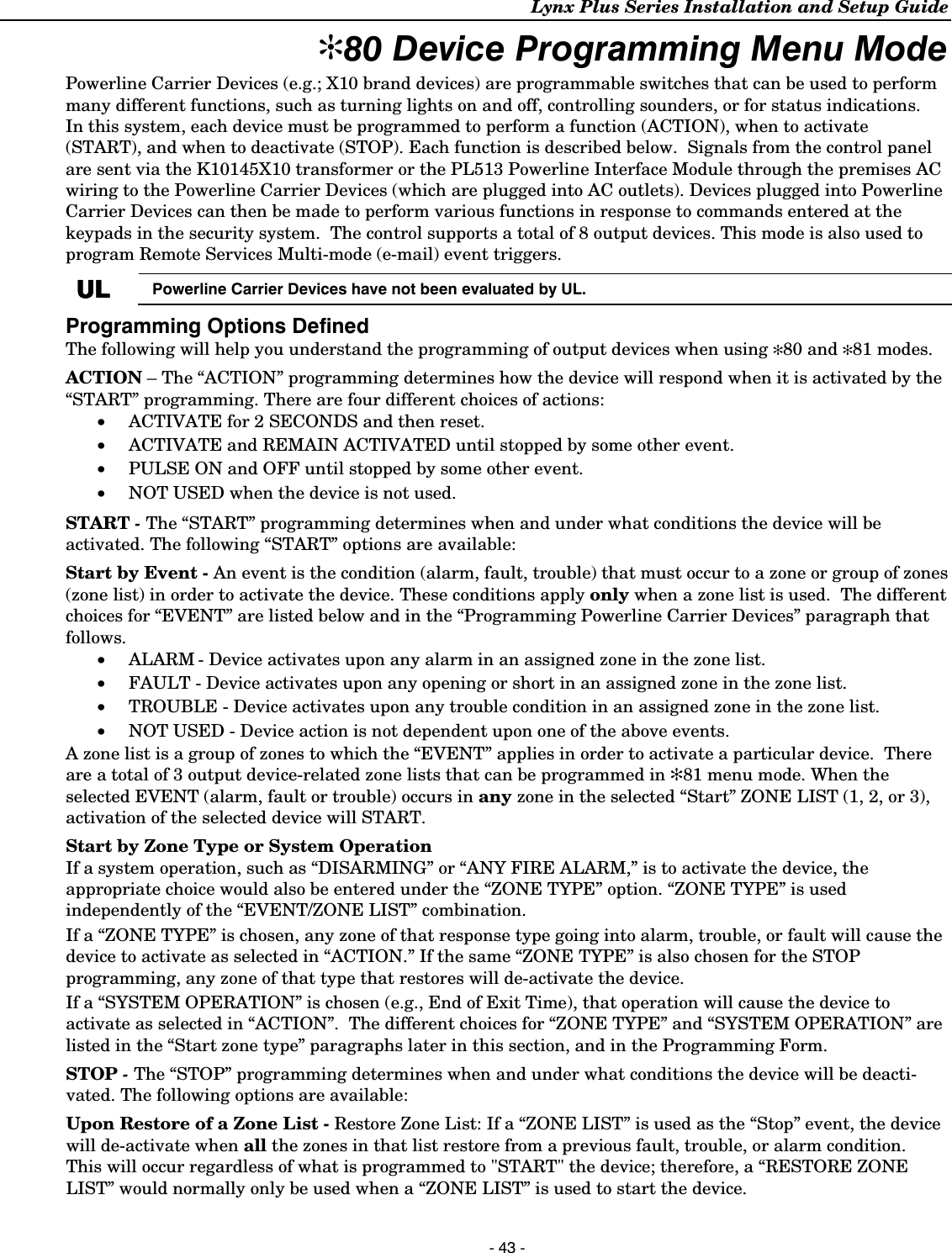
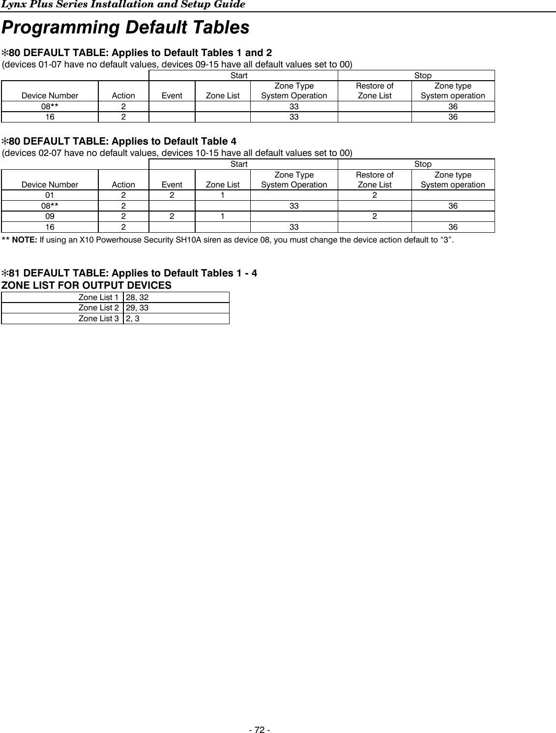
![Lynx Plus Series Installation and Setup Guide - 44 - ✻80 Device Programming Menu Mode Upon a Zone Type or System Operation - Zone Type/System Operation: Instead of using a “RESTORE ZONE LIST”, a specific zone (response) type or system operation action can be selected to de-activate the device. If a specific “ZONE TYPE” is chosen, any zone of that response type that restores from a previous alarm, trouble, or fault condition will cause the device to de-activate. If a “SYSTEM OPERATION” is chosen, that operation will cause the device to de-activate. During normal system operation, any devices may be: • Manually started by keypad entry of: Code* + [#] + 4 + “nn;” OR • Manually stopped by keypad entry of: Code* + [#] + 7 + “nn,” where “nn” = the 2-digit device number to be controlled. * Code is required for devices 07 and 08. For devices 01-06, code is not required. See User Manual for more information. Programming Powerline Carrier Devices While in Program mode, press ✻80 to enter Device Programming Menu Mode. This mode is used to program all output devices used in the system. Refer to the output device table for ✻80 on the separate programming form when programming output devices. Note: The House ID of the Powerline Carrier Devices must be entered in data field ✻25. The following explains these prompts in detail. The left two columns identify the prompts and list the available entries. The right-most column provides a further explanation of the entries. Note: Entering a number other than one specified will give unpredictable results. ZT16 is only available on the LynxSIA Plus version of the control panel. 80808080 DEVICE DEVICE DEVICE DEVICE PROG PROG PROG PROG MENUMENUMENUMENU Powerline Carrier Device Programming Entering “0” exits mode, upon which this prompt blinks, indicating that the mode is inactive. Entering “1” advances to the next prompt below. SELECTIONS 0 = exit mode 1 = enter mode A01A01A01A01 DEVICE DEVICE DEVICE DEVICE NUMBERNUMBERNUMBERNUMBER Device Number Enter the 2-digit device number to be programmed. SELECTIONS 01-08 = X10 device number to be programmed 09-16 = Multi-mode (e-mail) event triggers [✻] = continue 00 = exit Device Programming mode b DEVICE DEVICE DEVICE DEVICE ACTIONACTIONACTIONACTION Device Action Enter the 1-digit device action (0-3) for the device being programmed (current action is displayed). Notes: (1) If “3” is entered (pulse), only up to 3 different devices can be pulsed if one of the devices is a siren/horn (X10 Powerhouse Security model SH10A). In addition, the siren/horn cannot be manually activated using the lights on/lights off keypad commands. (2) If using an X10 Powerhouse Security SH10A siren, you must use device action “3” and change the device action default to “3” (if using default table 2 or 4). SELECTIONS 0= No response 1 = Close for 2 seconds 2 = Close and Stay Closed 3 = Continuous Pulse on & off (1 sec ON, 1 sec OFF) [✻] = continue [#] = return to previous prompt](https://usermanual.wiki/Ademco/8DLLYNXPLUS2.Users-Manual-Lynx-Plus/User-Guide-2014867-Page-43.png)
![Lynx Plus Series Installation and Setup Guide - 45 - ✻80 Device Programming Menu Mode CCCC START START START START EVENT EVENT EVENT EVENT TYPETYPETYPETYPE Start Event Type Enter the 1-digit start event type (0-3) to activate the device being programmed. A zone list must be used in conjunction with an event. If a zone type/system operation is to be used instead of an event, enter “0”. SELECTIONS 0 = Not used 1 = Alarm 2 = Fault 3 = Trouble [✻] = continue [#] = return to previous prompt d STARSTARSTARSTART T T T ZONE ZONE ZONE ZONE LISTLISTLISTLIST Start Zone List If a zone list will be used to start the device action, enter the 1-digit zone list number for the device being programmed. SELECTIONS 1-3 = zone list number (to be programmed in field ✱81) 0 = zone list not used for this device [✻] = continue [#] = return to previous prompt EEEE STARTSTARTSTARTSTART ZONE ZONE ZONE ZONE TYPETYPETYPETYPE Start Zone Type If a zone type or system operation will be used to start the device action, enter the appropriate 2-digit code for the device being programmed (see table that follows). Choices for zone types 00 = Not Used 07 = 24 Hr Audible 01 = Entry/Exit #1 08 = 24 Hr Aux 02 = Entry/Exit #2 09 = Fire without verification 03 = Perimeter 10 = Interior w/Delay 04 = Interior Follower 14 = Carbon Monoxide 05 = Trouble Day/Alarm Night 16 = Fire with verification (SIA Only) 06 = 24 Hr Silent 24 = Silent Burglary Choices for system operation 20 = Arming–Stay 38 = Chime 21 = Arming–Away 52 = Kissoff 22 = Disarm. (Code + OFF) 39 = Any Fire Alarm 31 = End of Exit Time 40 = Bypassing 32 = Start of Entry Time 42 = System Battery Low 33 = Any Alarm (except ZT 08, 09, 14 or 16) 43 = Communications Failure 36 = At Bell Timeout** 58 = Duress ** Or at Disarming (which ever occurs earlier) SIA ZT 16 must be used in SIA fire applications. SELECTIONS 01-58 = zone type to start this device action (select only those that are applicable 00 = zone type not used for this device [✻] = continue [#] = return to previous prompt FFFF STOP STOP STOP STOP ZONE ZONE ZONE ZONE LIST LIST LIST LIST Stop Zone List If a zone list will be used to STOP, or restore, the device action, enter the zone list number 1, 2, or 3 (to be programmed in ✻81 mode). If not used, enter “0”. SELECTIONS 1-3 = zone list to stop this device action 0 = zone list not used [✻] = continue [#] = return to previous prompt](https://usermanual.wiki/Ademco/8DLLYNXPLUS2.Users-Manual-Lynx-Plus/User-Guide-2014867-Page-44.png)
![Lynx Plus Series Installation and Setup Guide - 46 - ✻80 Device Programming Menu Mode 1A1A1A1A STOP STOP STOP STOP ZONE ZONE ZONE ZONE TYPETYPETYPETYPE Stop Zone Type If a zone type or system operation will be used to STOP the device action, enter the appropriate 2-digit code (see the "ZT" choices listed above). If not, enter 00. The display then returns to the DEVICE NUMBER prompt (A) so that you can enter the next device number to be programmed, or enter [0][0] to end device programming. SELECTIONS 01-58 = zone type to stop this device action (select only those that are applicable 00 = zone type not used for this device [✻] = continue [#] = return to previous prompt](https://usermanual.wiki/Ademco/8DLLYNXPLUS2.Users-Manual-Lynx-Plus/User-Guide-2014867-Page-45.png)
![Lynx Plus Series Installation and Setup Guide - 47 - ✻81 Zone List Menu Mode While in Program mode, press ✻81 to enter Zone List Menu Mode. This mode is used to program zone lists for output devices (programmed in ✻80 Device Programming Menu Mode) or Chime-by-Zone in Zone List 3. The following explains these prompts in detail. The left two columns identify the prompts and list the available entries. The right-most column provides a further explanation of the entries. Notes: (1) Any list may include any or all of the systems zone numbers (2) A zone list can be assigned to more than one Powerline Carrier Device (3) Entering a number other than one specified will give unpredictable results. (4) Do not assign zones with zone types 20, 21 or 22 to a zone list. (5) LynxSIA Plus ONLY Zone List 2 should be used for Cross Zoning. When creating zone list 2 for cross zoning, include only 2 zones assigned to zone types 3, 4, or 5. If interior zones (zone type 4) are cross zoned, then both zones in zone list 2 must be interior zones. Do not cross zone more than 2 zones, or zone types that have delays (entry/exit zones, interior w/delay), or 24-hour zones, as these choices may produce unpredictable operation and may not function as intended. If cross zoning is used, zone list 2 should not be used for other purposes, such as triggering powerline carrier devices. If field ✻39 has been set to “0” (no cross zoning), then Zone List 2 can be used for other purposes. 81818181 ZONE ZONE ZONE ZONE LISTS LISTS LISTS LISTS MENUMENUMENUMENU Zone List Programming Entering “1” advances to the next prompt below. Entering “0” exits mode, upon which this prompt blinks, indicating the mode is inactive. SELECTIONS 0 = exit mode 1 = enter mode A01A01A01A01 ZOZOZOZONENENENE LIST LIST LIST LIST NUMBERNUMBERNUMBERNUMBER Zone List Number Enter the Zone List Number 01, 02, or 03 to program (or 00 if no zone lists are used). Note: Use Zone List 3 for Chime by Zone feature. SELECTIONS 01-03 = zone list number to be programmed 00 = exit Zone List mode [✻] = continue b ZN ZN ZN ZN ENTRYENTRYENTRYENTRY TO TO TO TO LIST LIST LIST LIST Zone entry to list Enter the 2-digit zone number for each zone number to add to the zone list by first entering the zone number, then the [✻] key (for example, 01✻ 02✻ 03✻). The system will announce the Voice Descriptor for the selected zone, if it is programmed. After all desired zones are enrolled, enter “00” to advance. SELECTIONS 01-41, 95, 96, 99 = zone numbers to add to zone list [✻] = accept zone number and enter the next zone number 00 = accept zone number(s) and continue to next prompt CCCC DEL DEL DEL DEL WHOLEWHOLEWHOLEWHOLE ZN ZN ZN ZN LSTLSTLSTLST Delete Entire Zone List Enter “1” to delete the zone list. All zones in the zone list will be deleted automatically and programming will return to the ZONE LIST NUMBER prompt. Enter “0” to save the zone list or delete specific zones from the list. SELECTIONS 0 = don’t delete; continue to next prompt 1 = delete the current zone list d DELDELDELDEL 1 ZN 1 ZN 1 ZN 1 ZN FRM FRM FRM FRM LST LST LST LST Delete Zones from List? Enter “0” to save the entire zone list. Programming will return to the ZONE LIST NUMBER prompt. Enter “1” to delete a zone or zones in a zone list. SELECTIONS 1 = continue to delete zones prompt 0 = don’t delete; continue to next zone list number prompt (A01) [#] = return to zone list number prompt (A01)](https://usermanual.wiki/Ademco/8DLLYNXPLUS2.Users-Manual-Lynx-Plus/User-Guide-2014867-Page-46.png)
![Lynx Plus Series Installation and Setup Guide - 48 - ✻81 Zone List Menu Mode EEEE DELETE DELETE DELETE DELETE ZONESZONESZONESZONES Delete Zones Enter each 2-digit zone number to be deleted from the current zone list, followed by the [✻] key. When deleting a zone(s) from the zone list, if the selected zone has a Voice Descriptor programmed, upon deletion it will be announced as a confirmation that it has been deleted. After all zones to be deleted are entered, enter “00” to return to the ZONE LIST NUMBER prompt so that another list can be programmed, if desired. SELECTIONS [✻] = delete zone and enter next zone to be deleted 00 = delete zone and return to next zone list number prompt (A01) desired)](https://usermanual.wiki/Ademco/8DLLYNXPLUS2.Users-Manual-Lynx-Plus/User-Guide-2014867-Page-47.png)
![Lynx Plus Series Installation and Setup Guide - 49 - ✻83 Enhanced Sequential Mode By using this mode, you can add, delete, or change the serial number of a transmitter in a zone, but retain all other existing data that has been programmed for that zone. Note that the ✻83 Enhanced Sequential mode requires that all zone information must first be entered using the ✻56 Enhanced Zone Programming mode for all zones below zone number 26 (4 button key area). Certain button-type transmitters have more than one button (e.g., 5804). Note that each button must be assigned to a different zone. Similarly, the 5816 Transmitter has contact terminals and a reed switch for use with a magnet. If using both, each must also be assigned to a different zone. This means that the procedures that follow must be repeated for each button-type zone below zone number 26 or contact on the transmitter. Four zone button-type devices are held in zones 26 and above. They will be started on boundaries of zones 26, 30, 34, and 38. These four zone button-type devices will have the option to have all information entered in this field. One entry will set the loop number, report code, zone type, and input device type for all 4 buttons, and a second entry will enter one serial number into four zones. The following explains these prompts in detail. The left column identifies the prompts and lists the available entries. The right column provides a further explanation of the entries. Notes: (1) Use this mode only after all other zone information has been programmed, including transmitter loop numbers except for button-type zones over zone number 26. The panel will stop at zones 26, 30, 34 and 38 and zone data can be entered as a default here (2) Any zone which already has a serial number learned in will not be accessible in ✻83 Enhanced Sequential mode. (3) Entry of a number other than one specified will give unpredictable results. (4) In Enhanced Sequential Mode, 4 button type keys will always be enrolled simultaneously. They will be stopped at the 4 button boundaries of 26, 30, 34 and 38, provided the zone is free of a serial number. If the first zone of the key has a serial number enrolled, the remaining keys cannot be programmed in sequential mode. In addition, if the zone has not been set up (duplicate loop, missing zone type, etc.) only entries 0 (skip to the next zone) and 4 (copy the key template) will be allowed. (5) You may find it convenient to adjust the volume setting before entering the Programming Mode. This will allow you to clearly hear feedback announcements or system beeps. A0A0A0A02222 ZONE ZONE ZONE ZONE NUMBERNUMBERNUMBERNUMBER Zone Number Enter the 2-digit zone number of the first transmitter to have its serial number entered. The system will announce the Voice Descriptor for the selected zone number, if it is programmed. Press [✻] to continue. Starting with this zone number, the system will search for the first transmitter that has all of the following attributes pre-programmed in ✻56 ENHANCED ZONE PROGRAMMING: a) The appropriate input type was selected in ✻56 (RF, UR, or BR programmed) b) The appropriate loop number was selected in ✻56. c) No serial number has been programmed d) Zone type If the first zone number entered does not have one or more of the above attributes, the system will search its database for the first zone that does, and will display it at the enroll SERIAL NUMBER prompt (1b). Enter 00 to exit. Prompt “83” blinks, indicating the mode is inactive. Note: Two exceptions to the requirement above exist for keys. Four zone button type devices (zone numbers 26, 30, 34, and 38) will be stopped only if there are no serial numbers enrolled in all 4 zones of the key, regardless of the attributes that have been entered. In addition, zone types are not required to be present. In this case, 1A, Option 4 must be selected prior to “Learn”. SELECTIONS Enter 2-digit zone number. [✻] = continue; system searches for zones not yet entered (for zones 2 through 25 a zone type must be entered), then advances to ENROLL SERIAL NUMBER prompt “1b” 00 = exit Sequential mode](https://usermanual.wiki/Ademco/8DLLYNXPLUS2.Users-Manual-Lynx-Plus/User-Guide-2014867-Page-48.png)
![Lynx Plus Series Installation and Setup Guide - 50 - ✻83 Enhanced Sequential Mode IAIAIAIA ENROLL ENROLL ENROLL ENROLL MODEMODEMODEMODE Enroll Mode This prompt is used to enter, view or confirm a serial number. If “L” is displayed, the serial number for this transmitter has already been entered; however, it may still be confirmed, viewed or deleted. Enter serial number - If the transmitter’s serial number has not been previously entered, you may enter the enroll serial number mode (1A) by entering “1”. Copy serial number - Enter “2” to copy the last serial number that was entered. A serial number must be entered in order to be copied. If no serial is stored in the buffer and a copy is attempted the panel will emit a long beep indicating an invalid operation. View serial number - If the transmitter’s serial number has been previously entered, you may, view the present serial number by entering “3”. If view is selected each digit will be re-displayed, and the keypad will beep once for digits 1-6, and three times for the last digit. Once the serial number has been entered by either selecting a “1” or a “2”, you will return to this prompt with the “L” on the display. The serial number/loop number combination that was entered can be confirmed by getting two transmissions (fault and restore) from the RF or UR device or one transmission from the BR device. If a transmission is received that matches the serial number and loop number entered, the system will announce the Voice Descriptor for the loop followed by three beeps, and a “C” will be displayed indicating that the received serial number and loop number trans-mission has been confirmed to match. No further transmissions will be received. When confirming a 4 button key, only the serial number is confirmed, since it assumed that all loops are used. Pressing any key will allow a confirmation. *Long beep indicates illegal entries, or duplicate serial number/loop entry* When the last zone has been entered, the display will remain on that zone. To exit this mode and return to data field program mode, enter 00 at the ZONE NUMBER prompt. When all zones have been programmed, test each zone using the system’s Test mode. Do not use the Transmitter ID Sniffer mode for this, since it will only check for transmission of one zone on a particular transmitter, and not the zones assigned to each additional loop. For Zones 26-29, 30-33, 34-37, and 38-41 any loop can be used for RF enrollment. If enrolling via RF, it will be confirmed without additional transmissions. Notes: (1) A valid template or key has 4 existing zones, each with a zone type, unique loop number. (2) Option 2 is not applicable for 4 button key zones 26-29, 30-33, 34-37, & 38-41. (3) If the display automatically returns to "1A" rather than "1b" the configuration of the key is not valid. At that point copy template, skip, or return are the only legal entries. (4) If option 3 or 9 is selected, the serial number can be viewed or deleted but only if “L” is displayed. If the “L” is not displayed the panel will emit a long beep. (5) If option 4 is selected template acceptance is indicated by two beeps after copying. A single long beep, emitted when copying indicates the template is not valid. SELECTIONS 0 = advance to next zone to be enrolled 1 = enter now and proceed to SERIAL NUMBER prompt (1b). For 4 button keys (zones 26-29, 30-33, 34-37, & 38-41) the serial number will be enrolled to all four buttons. If enrolling a key, the panel will emit a long beep when entering a 1 to indicate that the present key set up is invalid. 2 = copy the previous serial number entry from the buffer. 3 = view existing serial number. 4 = copy the 4 button key template that has been set in zone numbers 26-29 (all zone parameters except serial numbers). (Only valid on zones 30-33, 34-37, & 38-41 that do not have serial numbers enrolled.) 9 = delete existing serial. Go to the (1A) prompt. For 4-button key, zones 26-29, 30-33, 34-37, & 38-41 have serial numbers. Delete all four at one time. [✻] = advance to next zone to be enrolled [#] = return to previous prompt (A)](https://usermanual.wiki/Ademco/8DLLYNXPLUS2.Users-Manual-Lynx-Plus/User-Guide-2014867-Page-49.png)
![Lynx Plus Series Installation and Setup Guide - 51 - ✻83 Enhanced Sequential Mode IIIIb SERIAL SERIAL SERIAL SERIAL NUMBERNUMBERNUMBERNUMBER Serial Number This prompt can be used to enroll the transmitter serial number via RF transmission or manually. If using the RF Learning Mode there is no need to manually enter a serial number. Proceed directly to RF Learning. Upon entering the Serial Number mode, the Zone Descriptors will be announced. Note: BR type devices can be enrolled only by transmission from BR devices. Likewise, UR and RF devices can only be enrolled by transmission from a UR or RF device RF Learning Two (2) transmissions (2 key depressions) at least five seconds apart, will be required for BR type or four (4) transmissions (fault, restore and fault, restore) for UR or RF type. If the learned serial number has a different loop number than that entered in ✻56 the system will announce the Voice Descriptor, if it is programmed, followed by two beeps and will return to Prompt (1A) and “L” will be displayed. If the loop number captured by RF transmission and that entered in ✻56 mode match, the system will announce the Voice Descriptor, if it is programmed, followed by three beeps and return to Prompt (1A) and “LC” will be displayed. No additional transmissions are needed for confirmation. Manual Entry Enter the 7-digit serial number printed on the transmitter. If you enter an incorrect digit, press the [#] key to backup to prompt (1A) and start over. When all 7 digits are entered, press the [✻] key. If less than 7 digits are entered, the keypad will emit a single long beep and return to the (1A) prompt without displaying the “L”. If more than 7 digits have been entered, the first 6 digits will be saved along with the last digit that was entered (entering 123456789 yields the serial number 1234569). Note: The system will return to prompt (1A) if an entry is not made within 52 seconds. SELECTIONS Enter transmitter’s 7- digit serial number via RF learning or manually. [#] = return to (1A) prompt and reject whatever serial number entries have been made. [✻] = return to (1A) prompt (if a valid serial number has been enrolled, “L” is displayed and the serial number will be copied into EEROM and the last serial entered buffer. Note: For zones 26, 30, 34 and 38 only BR type devices can be used. FFFF DELETE DELETE DELETE DELETE ZONEZONEZONEZONE CONF CONF CONF CONF Delete Serial Number This function deletes only the serial number. Entering a “9” at prompt (1A). Confirmation of the delete request will cause deletion of the serial number pertaining to the zone being programmed. Note: Entering a “9” at prompt (1A) will cause the panel to return to prompt (1A) regardless of the confirmation answer. SELECTIONS 0 = discard the delete request 1 = confirm requested delete Note: In Enhanced Sequential Learn Mode, 4 button type keys will always be learned simultaneously. They will be stopped at the 4 button boundaries of 26, 30, 34 and 38, provided the zone is free of a serial number. If the first zone of the key has a serial number learned, the remaining keys cannot be programmed in sequential learn mode. In addition, if the zone has not been set up (duplicate loop, missing zone type, etc.) only entries 0 (skip to the next zone) and 4 (copy the key template) will be allowed.](https://usermanual.wiki/Ademco/8DLLYNXPLUS2.Users-Manual-Lynx-Plus/User-Guide-2014867-Page-50.png)
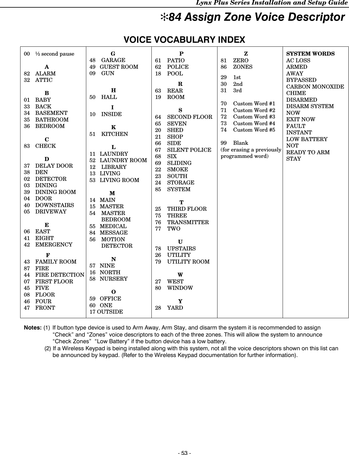
![Lynx Plus Series Installation and Setup Guide - 52 - ✻84 Assign Zone Voice Descriptors Use this mode to assign voice descriptors for each zone. These are the descriptors that are announced when the system announces any event involving a zone number. Each descriptor can consist of up to 3 words. To access this mode, Enter ✻84 while in Programming mode. The following explains these prompts in detail. The left column identifies the prompts and lists the available entries. The right column provides a further explanation of the entries. Note: Entering a number other than the one specified will give unpredictable results. 84848484 ZONEZONEZONEZONE VOICE VOICE VOICE VOICE DESCDESCDESCDESC Assign Zone Voice Descriptors Entering “1” advances to the next prompt below. Entering “0” exits mode, upon which prompt “84” blinks, indicating the mode is inactive. SELECTIONS 0 = exit mode 1 = enter mode AAAA ZONE ZONE ZONE ZONE NUMBERNUMBERNUMBERNUMBER Zone Number Enter the 2-digit zone number for which this descriptor is being assigned, then press [✻]. The Voice Descriptor for the selected zone will be announced, if it is programmed. SELECTIONS [✻] = continue to next prompt (any existing descriptors will be announced, then descriptor 1 will be repeated) 00 = exit voice descriptor mode b DESCRIPTOR 1DESCRIPTOR 1DESCRIPTOR 1DESCRIPTOR 1 . Descriptor 1 Enter the first word of the descriptor for the selected zone. Use the [6] or [8] key to advance as described. To change the entered index number before pressing [6] or [8], simply press [#] + desired 2-digit vocabulary index number. If descriptor 1 is not desired, enter [#] + 99 (blank), then press [8] to return to zone number prompt. SELECTIONS Enter [#] + 2-digit vocabulary index number of first descriptor word for this zone. 6 = accept word and advance to descriptor 2 (descriptor 2 will be announced) 8 = accept word and advance to prompt (A) for next zone. Press any other key to repeat the selected word. CCCC DESCRIPTOR 2DESCRIPTOR 2DESCRIPTOR 2DESCRIPTOR 2 Descriptor 2 Enter the second word of the descriptor for the selected zone. Use the [6] or [8] key to advance as described. To change the entered index number before pressing [6] or [8], simply press [#] + desired 2-digit vocabulary index number. If descriptor 1 is not desired, enter [#] + 99 (blank), then press [8] to return to zone number prompt. SELECTIONS Enter [#] + 2-digit vocabulary index number of second descriptor word for this zone. 6 = accept word and advance to descriptor 3 (descriptor 3 will be announced) 8 = accept word and advance to prompt (A) for next zone. Press any other key to repeat the selected word. d DESCRIPTOR 3DESCRIPTOR 3DESCRIPTOR 3DESCRIPTOR 3 Descriptor 3 Enter the last word of the descriptor for the selected zone. Use the [6] or [8] key to advance as described. To change the entered index number before pressing [6] or [8], simply press [#] + desired 2-digit vocabulary index number. If descriptor 3 is not desired, enter [#] + 99 (blank), then press [8] to return to zone number prompt. SELECTIONS Enter [#] + 2-digit vocabulary index number of third descriptor word for this zone. 6 or 8 = accept word and advance to prompt (A) for next zone. Zone descriptor will be announced. Press any other key to repeat the selected word.](https://usermanual.wiki/Ademco/8DLLYNXPLUS2.Users-Manual-Lynx-Plus/User-Guide-2014867-Page-51.png)
![Lynx Plus Series Installation and Setup Guide - 54 - ✻85 Record Custom Voice Descriptors Use this mode to record up to 5 custom voice descriptors. To enter this mode, enter ✻85 while in Programming mode. Note: Entering a number other than one specified will give unpredictable results. 85858585 REC REC REC REC VOICE VOICE VOICE VOICE DESCRDESCRDESCRDESCR Assign Custom Voice Descriptors Entering “1” advances to the next prompt below. Entering “0” exits mode, upon which “85” prompt blinks, indicating the mode is inactive. SELECTIONS 0 = exit mode 1 = enter mode AAAA CUSTOM CUSTOM CUSTOM CUSTOM DESCDESCDESCDESC # Custom Descriptor Number Record up to 5 custom words. Enter 7 + d + [✻] Note: d = 0-4, each representing custom word 70, 71, 72, 73, or 74, respectively. Any existing word will be announced Press [#] to start recorder. Begin speaking immediately after the third beep. Speak the desired word clearly near the microphone. Recording stops after 1.5 seconds. SELECTIONS 0 = exit mode 1 = enter mode 6 = accept word and ready to record next descriptor prompt (A….7d) [#] = re-record descriptor 00 = exit Record mode after pressing 6 to accept word Press any key to repeat the recorded word.](https://usermanual.wiki/Ademco/8DLLYNXPLUS2.Users-Manual-Lynx-Plus/User-Guide-2014867-Page-53.png)
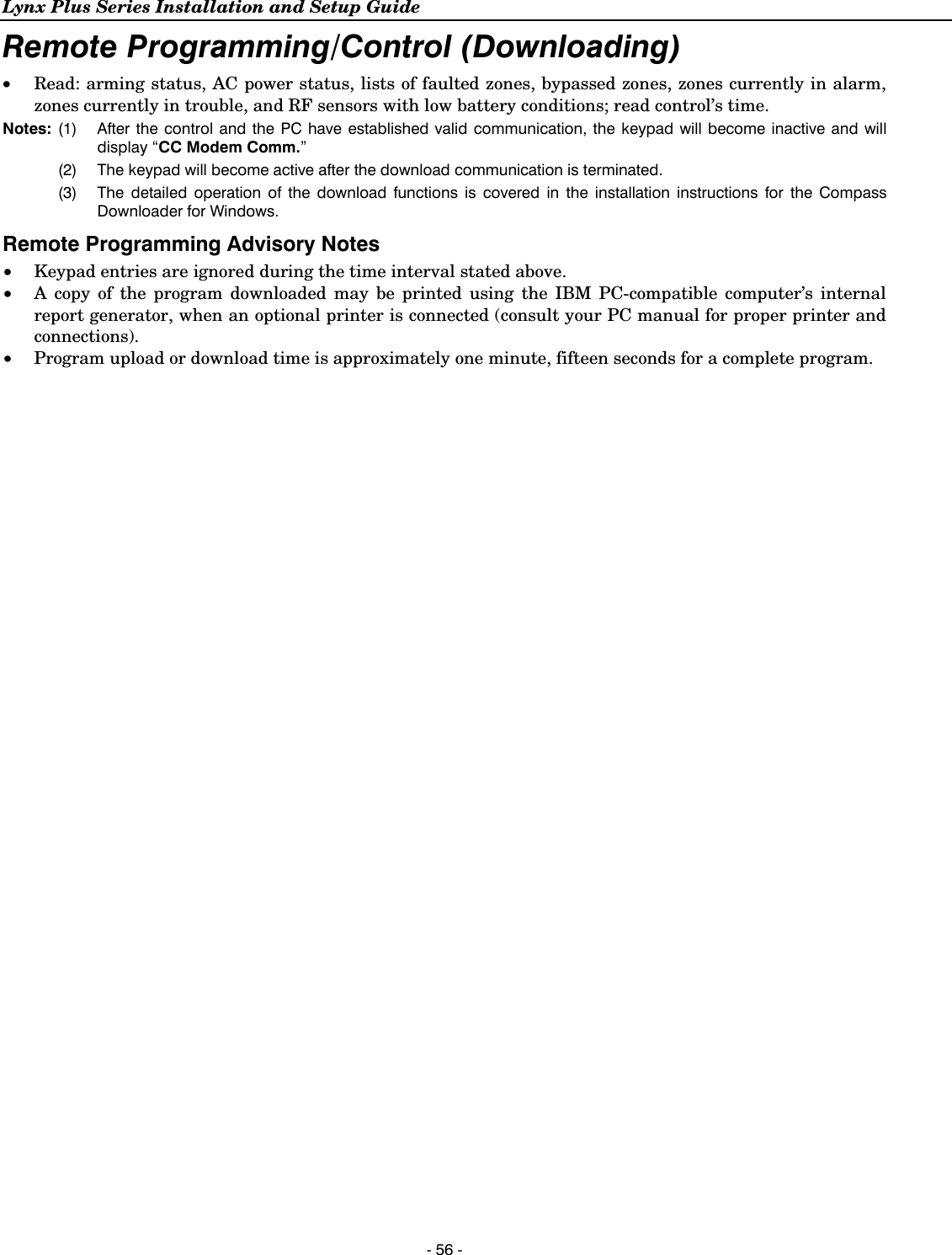
![Lynx Plus Series Installation and Setup Guide - 55 - Remote Programming/Control (Downloading) General Information The control panel can be remotely programmed from an IBM-compatible Personal Computer (PC), Compass Downloader, a HAYES Modem or via a capable GSM or IP communications device. ULULULUL Downloading may only be performed if a technician is at the site. Multiple security levels protect remote programming against compromise by attempts to defeat the system. 1. Security Code Handshake: An 8-digit download ID code must be matched between the Control and downloader. 2. Site-Initiated Remote Programming: The installer or subscriber initiates the call from the subscriber premises by entering the Installer Code + # + 1, while the system is disarmed. All parameters can then be downloaded via the phone lines using a personal computer. 3. Station-Initiated Remote Programming: The operator calls the site from your office to initiate the download call. The Control hangs up and then calls back the PC via the preprogrammed telephone number. The unit can then be uploaded, downloaded, or controlled from your office. 4. Telco Handoff: The installer or subscriber performs a download session on the call initiated from the site or from local laptop computer by entering the Installer or Master Code + # + 1 at the control panel. 5. Data Encryption: Data passed between the PC and the Control is encrypted for security so that it is very difficult for a foreign device tapped into the phone line to take over communication and substitute system-compromising information. Equipment required to download to a system at the premises • An IBM PC compatible computer and appropriate interconnecting cables. • Either a HAYES brand SMARTMODEM 1200 (Level 1.2 or higher external or Level 1.1 or higher [with 4 position DIP switch] internal style), a HAYES brand Optima 336 external, a HAYES brand Optima 24 Plus FAX96, or an Ademco CIA Modem or via a capable GSM or IP communications device. • Compass Downloader for Windows (at revision level supporting Lynx Plus Series). Initial Download: Enter Installer Code + # + 5. This sets field ✻95 to 4 rings, and system to “no call-back” option. The download computer can then call the subscriber, make connection, and download all programming data. Flexible Callback: If enabled in field ✻93, the download operator can temporarily change the last 1, 2, or 3 digits (depending on selection) of the call back number. This allows the control to call back a computer other than the one programmed, which may be helpful at times of high computer traffic. Refer to 93 Flexible Callback programming field for additional information. Remote Programming Information If using Remote Programming, the Lynx Plus Series must be connected to the telephone line or to the Internet, as applicable. The downloading system can perform many functions when in communication with the Control. Besides uploading and downloading, the status of the system can be observed and various commands can be initiated, as follows: • Arm the system in the away mode; disarm the system. • Bypass a zone. • Force the system to accept a new program download. • Shut down communication functions (for nonpayment of monitoring fees in an owned system). • Shut down all security system functions (for nonpayment for a leased system). • Inhibit local keypad programming (prevents account takeover). • Command the system to upload a copy of its resident program to the office. • Set the time • View/Modify • X10/ Scheduling](https://usermanual.wiki/Ademco/8DLLYNXPLUS2.Users-Manual-Lynx-Plus/User-Guide-2014867-Page-54.png)
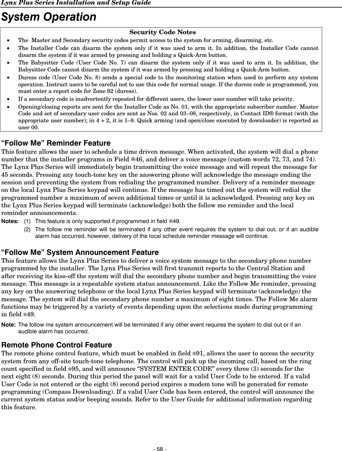
![Lynx Plus Series Installation and Setup Guide - 57 - System Operation Keypad Operation The keypad allows the user to arm and disarm the system, and perform other system functions, such as bypassing zones. Zone and system conditions (ALARM, trouble, bypass) are displayed on the keypad. When an alarm occurs, keypad sounding and external sounding will occur, and the zone(s) in alarm will be displayed on the keypad. Pressing any key will silence the keypad sounder for 10 seconds (only once). Disarming the system will silence both keypad and external sounders. When the system is disarmed, any zones that were in an alarm condition during the armed period will be displayed (memory of alarm). To clear this display, simply repeat the disarm sequence by entering the Security Code and pressing the OFF key. The keypad also features chime annunciation, and 3 panic key pairs for silent, audible, fire or personal emergency alarms. These keys can notify the central station of an alarm condition, if that service is connected. Panic Keys There are three panic key pairs that, if programmed, can be used to manually initiate alarms and send a report to the central station. Each can be individually programmed for 24-hour silent, audible, personal or fire emergency responses. The panic function is activated when both keys of the appropriate key pair are pressed at the same time. The panic functions are identified by the system as follows: Keys Displayed as Zone [1] & [✻] 95 [✻] & [#] 99 [3] & [#] 96 Important: For the silent panic functions to be of practical value, the system must be connected to a central station. Security Codes Installer Code The installer programs the 4-digit Installer Code initially as part of the programming procedure. The factory default Installer Code is 4-1-1-2, but may be changed in field ✻20. The Installer Code is the only code that allows entry into Programming mode and also, in normal operation mode, is used to enter the Master Code, which allows access to the normal functions of the system. Master Code In normal operation mode, the Installer Code is used to enter the 4-digit Master Security Code. Enter/change the Master code by installer. At the keypad enter: Installer Code + [CODE key] + [02] + desired 4-digit Master Code Change the Master code by master user. At the keypad enter: Current Master Code + [CODE key] + [02] + new Master Code + new Master Code again Secondary User Codes In normal operation mode, the Master Security Code can be used to assign up to 6 secondary 4-digit security codes, including a Babysitter Code and a Duress Code. The Master Code can also be used to remove secondary codes from the system (individually). Assign (or change) a secondary security code. At the keypad enter: Master Code + [CODE key] + User # (03–08) + desired Secondary Code The system will emit a single beep when each secondary code has been successfully entered. Delete a secondary security code. At the keypad enter: Master Code + [CODE key] + User # (03–08)](https://usermanual.wiki/Ademco/8DLLYNXPLUS2.Users-Manual-Lynx-Plus/User-Guide-2014867-Page-56.png)
![Lynx Plus Series Installation and Setup Guide - 59 - System Operation Exit Error Alarm Displays The system will display the following if programmed in Field *59. Entering a second Code + OFF sequence will clear the display. Display Meaning CA Alarm Cancelled Appears along with a zone indication if an exit or interior zone contained a fault during closing at the time the exit delay ended (e.g., exit door left open), but the system was disarmed during the entry delay time. The alarm sounder and keypad sound continuously, but stop when the system is disarmed. No message will be transmitted to the central station. EA Exit Error Appears along with a zone indication if an exit or interior zone contained a fault during closing when the exit delay ended, but the system was NOT disarmed during the entry delay time. The alarm sounder and keypad sound continuously until the system is disarmed (or timeout occurs). An Exit Alarm message is sent to the central station. OR if an alarm from an exit or interior zone occurs within two minutes after the end of an exit delay System Displays Display Meaning PC Remote Phone Remote Phone Control feature is active (Appears in place of the clock). PH Speakerphone System Speaker Phone mode is active (Appears in place of the clock). EE Invalid Entry Displayed when an invalid entry is made. Phn Follow Me Phone# Displayed when programming a Follow Me Phone Number. EE Invalid Entry Data entry error (invalid field number entered while programming. Re-enter a valid field number). System Trouble Displays Display Meaning CC Modem Comm Appears when the system is communicating with the central station for change of function or status verification. d1 StandBy Displayed approximately 4 seconds after power-up. After approximately 1 minute* the green “READY” LED should light and the real-time clock will appear. If the “d1” remains displayed for more than 1 minute, the system is disabled. *To bypass the 1-minute delay, press [#] + [0]. Important: Do not try to bypass 1minute delay before “d1” is displayed! FC Comm Fail Appears when a communication failure has occurred. This message clears only when the system is subsequently armed. 90 RF Jam Appears when the system has detected an RF jamming condition or excessive interference. 00 RF Keypad Indicates a problem with an RF keypad (i.e.; keypad low battery). No display If there is no keypad display at all, and the LED indicators are not lit, operating power for the system has stopped and the system is inoperative. If the display is lit and the AC display is off, the system is operating on battery power only. During an AC power loss, the backlighting will turn off and the indicators will flicker slightly to minimize deep discharge of the battery.](https://usermanual.wiki/Ademco/8DLLYNXPLUS2.Users-Manual-Lynx-Plus/User-Guide-2014867-Page-58.png)
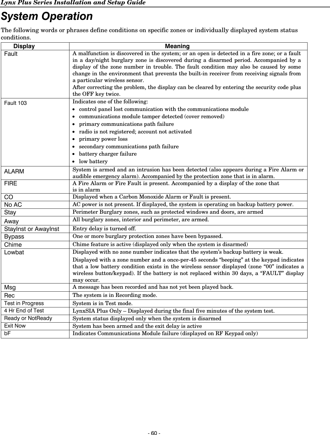
![Lynx Plus Series Installation and Setup Guide - 61 - System Operation ULULULUL Audio alarm verification has not been evaluated by UL. Audio Alarm Verification (Two-Way Voice Feature) This feature allows the central station operator to listen, talk to or conduct a two-way conversation with an individual(s) at the premises. It also assists the operator in gathering information about the nature and location of the alarm that may be helpful in responding to police and fire departments. All Lynx Plus Series control panels are capable of supporting the Two-Way Voice feature. The Lynx Plus Series does not make system announcements when the Two-Way voice feature is active. Activation Fire and CO alarms will not trigger an AAV session. A new Fire or CO alarm will end an AAV session that is in progress. The Lynx Plus Series sends the “alarm message” followed by a “Listen-in-to-Follow message” (Contact ID® code 606) to the Central Station. The Listen-in-to-Follow message causes the Central Station’s digital receiver to temporarily hold the phone line for approximately 1-minute. When the Lynx Plus Series receives the “kissoff” from the central station, indicating that the alarm message has been received, the Two-Way Voice (AAV) feature is activated in the (default) “Listen Mode” and sirens and keypad sounds are discontinued. The Lynx Plus Series transmits a beep acknowledgment to the Central Station, once per second. The beep alternates between two tones and indicates that the Lynx Plus Series is waiting for a session command from the Central Station operator. Once a command is issued the beep acknowledgement is discontinued, however, if a command is not issued within two minutes the system will “time out” and the call will be terminated. Operator Commands The Central Station operator begins the session, which last 5 minutes, by entering one of the valid AAV commands shown in the table below. The session may be extended 5 minutes, without changing the operating mode, by pressing the [7] key on the touch-tone phone. Selecting another operating mode also resets the session an additional 5 minutes. During the last minute of the 5 minute, session, the Lynx Plus Series generates two beeps every 30 seconds to alert the Central Station operator that the session is about to time out. The Central Station operator may then extend the session by pressing the [7] key on the touch-tone phone. If the session is not extended the phone line is disconnected, and the session is ended. Sessions may be ended at any time by pressing the [9] key on the touch-tone phone. The AAV modes are described as follows: Note: When entering AAV commands make sure the Central Station receiver has been disconnected from the phone line, otherwise AAV commands may not go through. Key Function 1 Talk Mode: Pressing the [1] key on the touch tone phone, enables one-way voice communication from the central station to the violated premises, and allows the operator to talk communicate through the Lynx Plus Series speaker. In this mode the ARMED (red) and READY (green) LEDs blink alternately. 2 VOX (Voice) Mode: Pressing the [2] key on the touch-tone phone, enables two-way voice communications between the central station and the violated premises. In this mode the ARMED (red) and READY (green) LEDs blink alternately. 3 Listen Mode: Pressing the [3] key on the touch-tone phone, enables one-way audio from the violated premises to the central station. The Listen Mode is the start up default mode of the voice feature and allows the operator to listen through the Lynx Plus Series microphone. This mode does not affect the existing LED pattern. 7 Extends the session 5 minutes without changing its operating mode. 9 Ends the session and disconnects the phone line.](https://usermanual.wiki/Ademco/8DLLYNXPLUS2.Users-Manual-Lynx-Plus/User-Guide-2014867-Page-60.png)
![Lynx Plus Series Installation and Setup Guide - 62 - Testing the System Test ModeAfter installation is completed, the security system should be carefully tested, as follows. 1. With the system in the disarmed state, check that all zones are intact. If the READY LED is not lit, press the [ ✻] key to display the faulted zone(s). Restore faulted zone(s), if necessary, so that the READY LED lights. Fault and restore every sensor individually to assure that it is being monitored by the system. 2. Enter the security code and press the TEST key. The outside sounder will sound for 1 second. “Test in Progress” will subsequently be displayed on the keypad. The control announces the zone’s voice descriptor (if programmed) followed by 3 beeps, each time a contact is faulted. A test report should be transmitted (if programmed) to the central station immediately. If the backup battery is discharged or missing, the sounder may not turn on and a LOW BATTERY report will be transmitted with a TEST report. The keypad will beep once every 45 seconds as a reminder that the system is in the Test mode. 3. To turn off the Test mode enter security code and press the OFF key. Notes: (1) Triggering a zone set to Arm AWAY, Arm STAY, or Disarm will take the system out of Test and cause that action. (2) BR type transmitters do not display during Test mode (keypad beeps only) (3) Macros cannot be run from the Test mode. (4) Test mode automatically ends after 4 hours. LynxSIA Plus ONLY (5) During the final 5 minutes (after 3 hours 55 minutes of Test mode), “4 Hr End of Test” is displayed on the keypad indicating that the end of Test mode is nearing. (6) Upon termination of a test mode all faulted 24-hour zones are treated as a trouble zones. (7) Fire verification is disabled when the system is in Test mode. Armed System TestAlarm messages will be sent to the central station during the following tests 1 and 2. Notify them in advance that tests will be in progress. 1. Arm the system and fault one or more zones. After 15 seconds (if optional dialer delay is selected), silence alarm sounder(s) by entering the code and pressing OFF. Check entry/exit delay zones. 2. Check the keypad-initiated alarms that are in the system by pressing the Panic key pairs. If the system has been programmed for audible emergency, the keypad will emit a steady alarm sound, and “ALARM” and zone number will be displayed. For Lynx Plus, silence the alarm by entering the security code and pressing OFF. For LynxSIA Plus, silence the alarm by entering the security code. If the system has been programmed for silent emergency, there will be no audible alarms or displays, but a report will be sent to the central station. 3. If Powerline Carrier Devices have been installed, test their programmed action. 4. Notify the central station when all tests are finished, and verify results with them. 5. To test the wireless part of the system and the RF receiver, perform the two additional tests described in the Installing Wireless Zones section: Sniffer mode and Go/No Go Test. Note: System Test mode (installer/master code + test) and Go/No Go Test (installer code + # + 8) will be automatically terminated after 3-1/2 to 4 hours if the installer or user does not manually terminate it. This ensures that fire and panic zones will not remain disabled. However, Sniffer mode (installer code + # + 3) does not automatically expire. You must manually exit (Installer/User Code + OFF) Sniffer mode to return to normal operation. TO THE INSTALLER Regular maintenance and inspection (at least annually) by the installer and frequent testing by the user are vital to continuous satisfactory operation of any alarm system. The installer should assume the responsibility of developing and offering a regular maintenance program to the user as well as acquainting the user with the proper operation and limitations of the alarm system and its component parts. Recommendations must be included for a specific program of frequent testing (at least weekly) to ensure the system’s proper operation at all times.](https://usermanual.wiki/Ademco/8DLLYNXPLUS2.Users-Manual-Lynx-Plus/User-Guide-2014867-Page-61.png)
![Lynx Plus Series Installation and Setup Guide - 63 - System Communication This section provides an explanation of formats this system accommodates for reporting alarms and other system conditions to the central station. The process of a successful transmission consists of both the method of communication between the control panel and the central station receiver, and the actual way the information is sent and displayed at the central station. Communication Overview When the panel calls the central station receiver, it waits to hear a “handshake” frequency from the receiver to confirm that the receiver is on-line and ready to receive its message. Once the panel hears the handshake it is programmed to listen for, it sends its message. The panel then waits for a “kissoff” frequency from the receiver acknowledging that the message was received and understood. If the handshake frequency is not given or is not understood by the panel, the panel will not send its message. Once the handshake frequency is received and understood by the panel, the panel will send its message. If there is an error in the transmission (the receiver does not receive a “valid” message), the kissoff frequency will not be given by the central station receiver. The panel will make eight attempts to the primary telephone number and eight attempts to the secondary telephone number (if programmed) to get a valid message through. If the panel is not successful after its numerous attempts, the keypad will display “FC Comm Failure.” If the secondary number is a pager, “FC Comm Failure” displays after the first 8 attempts to the primary number. The following chart defines the (handshake/kissoff) frequencies that the panel supports, and the different formats that can be sent for each. FORMAT HANDSHAKE TRANSMITS DATA KISSOFF TRANSMIT TIME Low Speed 3+1, 4+1, 4+2 1400Hz 1900Hz (10PPS) (Standard report) 1400Hz Under 15 seconds Sescoa/Radionics 3+1, 4+1, 4+2 2300Hz 1900Hz (20PPS) (Standard report) 2300Hz Under 10 seconds Express 4+2 1400–2300Hz DTMF (10 cps) 1400Hz Under 3 seconds Contact ID® 1400–2300Hz DTMF (10 cps) 1400Hz Under 3 seconds Report Code Formats 3+1 and 4+1 Standard Formats Comprise a 3- (or 4-) digit subscriber number and a single digit report code (e.g. alarm, trouble, restore, open, close, etc). 3+1 and 4+1 Expanded Formats Comprise a 3- (or 4-) digit subscriber number, and a 2-digit report code. The first digit is displayed on the first line, followed by a second line where the first digit is repeated 3 (or 4) times and followed by the second digit. This is the “expanded” digit. 4+2 Format Comprises a 4-digit subscriber number and 2-digit report code. ADEMCO Contact ID® Comprises a 4-digit subscriber number, 1-digit event qualifier Reporting Format (“new” or “restore”), 3-digit event code, and 3-digit zone number, user number, or system status number (see the following page) The following table shows the message formats for 3+1, 4+1 and 4+2 reports, where: SSS or SSSS = Subscriber ID C = Close Code (1st Digit) A = Alarm Code (1st digit) U = User Number (in hex) Z = Typically Zone Number* (2nd digit) Gg = Test Code (1st & 2nd digits) Tt = Trouble Code (1st & 2nd digits) R = Alarm Restore Code Bb = Bypass Code (1st & 2nd digits) RTt = Trouble Restore Code (1st & 2nd digits) EAC = AC Loss Code (1st & 2nd digits) RBb = Bypass Restore Code (1st & 2nd digits) LLB = Low Battery Code (1st & 2nd digits) RAAC = AC Restore Code (1st & 2nd digits) O = Open Code (1st Digit) RLLB = Battery Restore Code (1st & 2nd digits) *Zone numbers for: [*] & [#] = 99; [1] + [*] = 95; [3] + [#] = 96; Duress = 92](https://usermanual.wiki/Ademco/8DLLYNXPLUS2.Users-Manual-Lynx-Plus/User-Guide-2014867-Page-62.png)