Ademco 8DLLYNXREN-6 Wireless Controll Communicator User Manual PREK14114 8 ii
Honeywell International Inc. Wireless Controll Communicator PREK14114 8 ii
UserManual.wiki
>
Ademco
>
8DLLYNXREN 6 User Manual
Users Manual
Navigation menu
Upload a User Manual
Namespaces
Wiki Guide
HTML
PDF
Info
Views
User Manual
Discussion / Help
Navigation


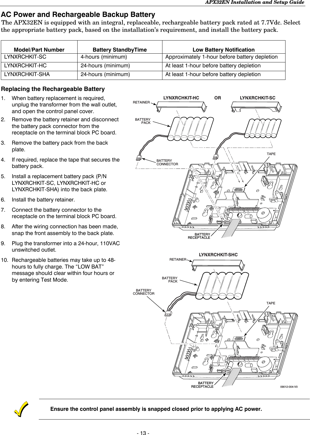
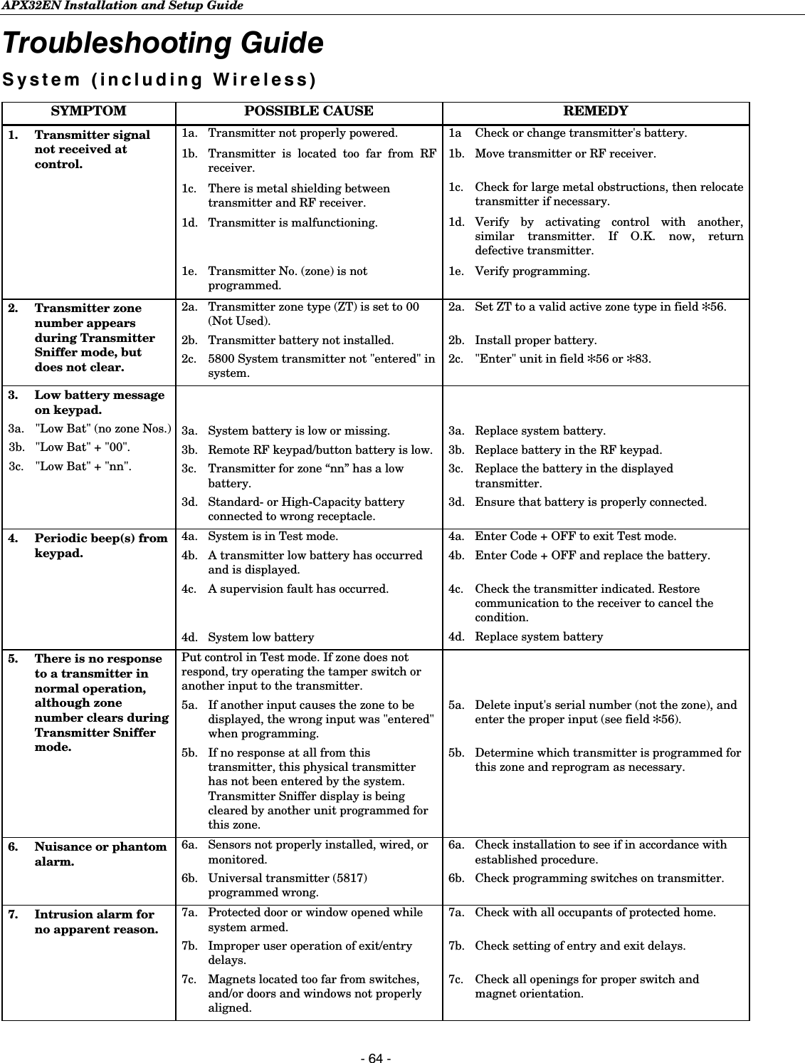
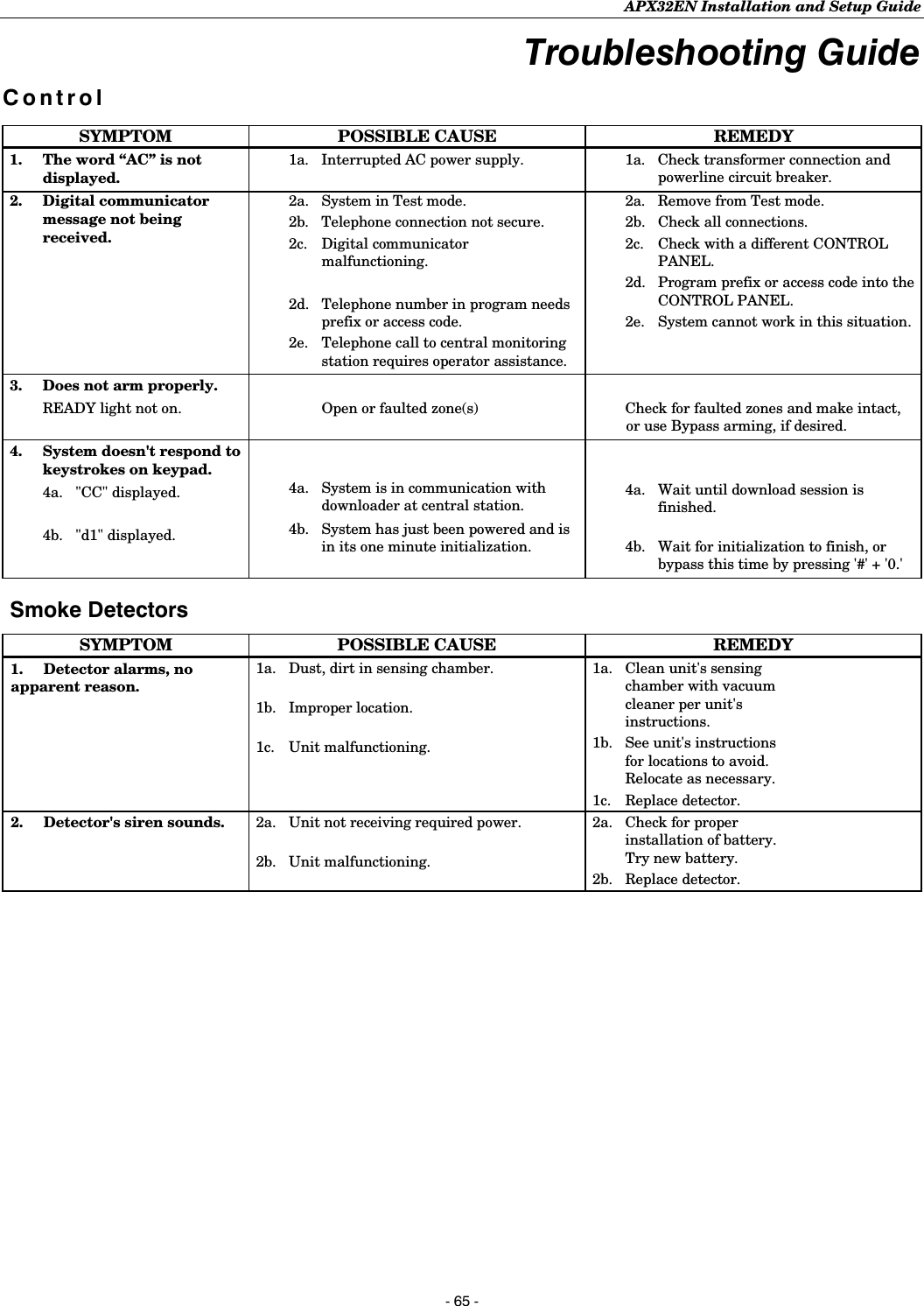
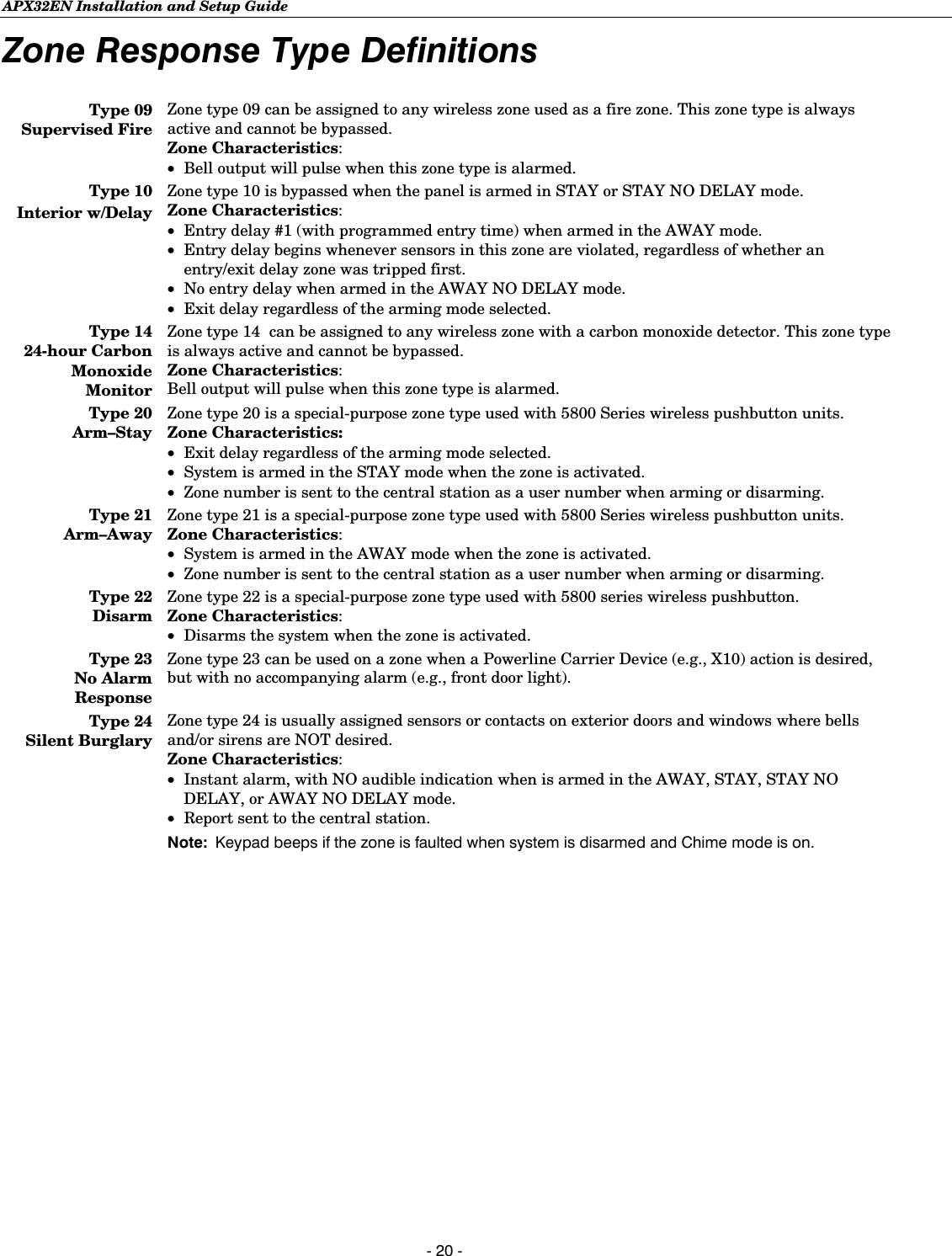
![APX32EN Installation and Setup Guide - 15 - • Button-type transmitters should be periodically tested for battery life. The 5801, 5802MN, 5802MN2, 5804, 5804BD, 5804BDV, and 5804E button transmitters have replaceable batteries. Using the Transmitter Sniffer Mode Use this mode after all transmitters have been entered to check that all transmitters have been properly programmed. 1. Enter Installer code (4112) + [#] + 3. Note: If the communicator is in the process of sending a report to the central station, the system will not go into the Sniffer mode. If so, wait a few minutes and try again. 2. The keypad will display all zone numbers, which have a non-zero Zone Type (even if serial numbers were not learned yet). Fault each transmitter in turn, causing each one to send a signal. As the system receives a signal from each of the transmitters, the zone number of that transmitter will disappear from the display. The transmitters may be checked upon installation, or in an installed system. 3. When all transmitters have been checked, exit Sniffer mode. Enter Installer Code (4112) + OFF. Notes: (1) Sniffer mode does not automatically expire. You must manually exit (Installer Code + OFF) Sniffer mode to return to normal operation. (2) All BR-type units must physically be activated to clear the display, since they do not automatically send check-in signals. (3) When one button of a transmitter (RF, UR, or BR) is activated, all zones assigned to other buttons on that transmitter are cleared. This also applies to 5816 and 5817 transmitters that have multiple loops (zones). (4) Any transmitter that is not “entered” will not turn off its zone number. Go/No Go Test Mode 5804E encrypted (High-Security) devices must be activated while the system is in Go/No Go Test Mode. Refer to the transmitter’s installation instructions for complete details. The system will confirm enrollment of the encrypted device by beeping two times. The Go/No Go tests will verify adequate RF signal strength from the proposed transmitter location, and allow you to reorient or relocate transmitters if necessary, before mounting the transmitters permanently. This mode is similar to the transmitter Test mode, except that the wireless receiver gain is reduced. This will enable you to make sure that the RF signal from each transmitter is received with sufficient signal amplitude when the system is in the normal operating mode. 1. Enter Installer Code (4112) + [#] + 8. 2. Once you have placed transmitters in their desired locations and the approximate length of wire to be run to sensors is connected to the transmitter's screw terminals (if used), fault each transmitter. Conducting this test with your hand wrapped around the transmitter will cause inaccurate results. On button type transmitters that have been programmed to set ARM AWAY, ARM STAY, or DISARM, pressing a button will take the system out of the Go/No Go Test mode and cause the programmed action to occur. Note: On button type transmitters that have been programmed to set ARM AWAY, ARM STAY, or DISARM, pressing a button will take the system out of the Go/No Go Test mode and cause the programmed action to occur. a. The keypad will beep three times indicating signal reception and will display the appropriate zone number. b. If the keypad does not beep, reorient or move the transmitter to another location. Usually a few inches in either direction is all that is required.3. If each transmitter produces the proper keypad response when it is faulted, you can then permanently mount each of the transmitters according to the instructions provided with them. 4. Exit the Go/No Go Test mode by entering: Installer Code (4112) + OFF.](https://usermanual.wiki/Ademco/8DLLYNXREN-6/User-Guide-883200-Page-15.png)
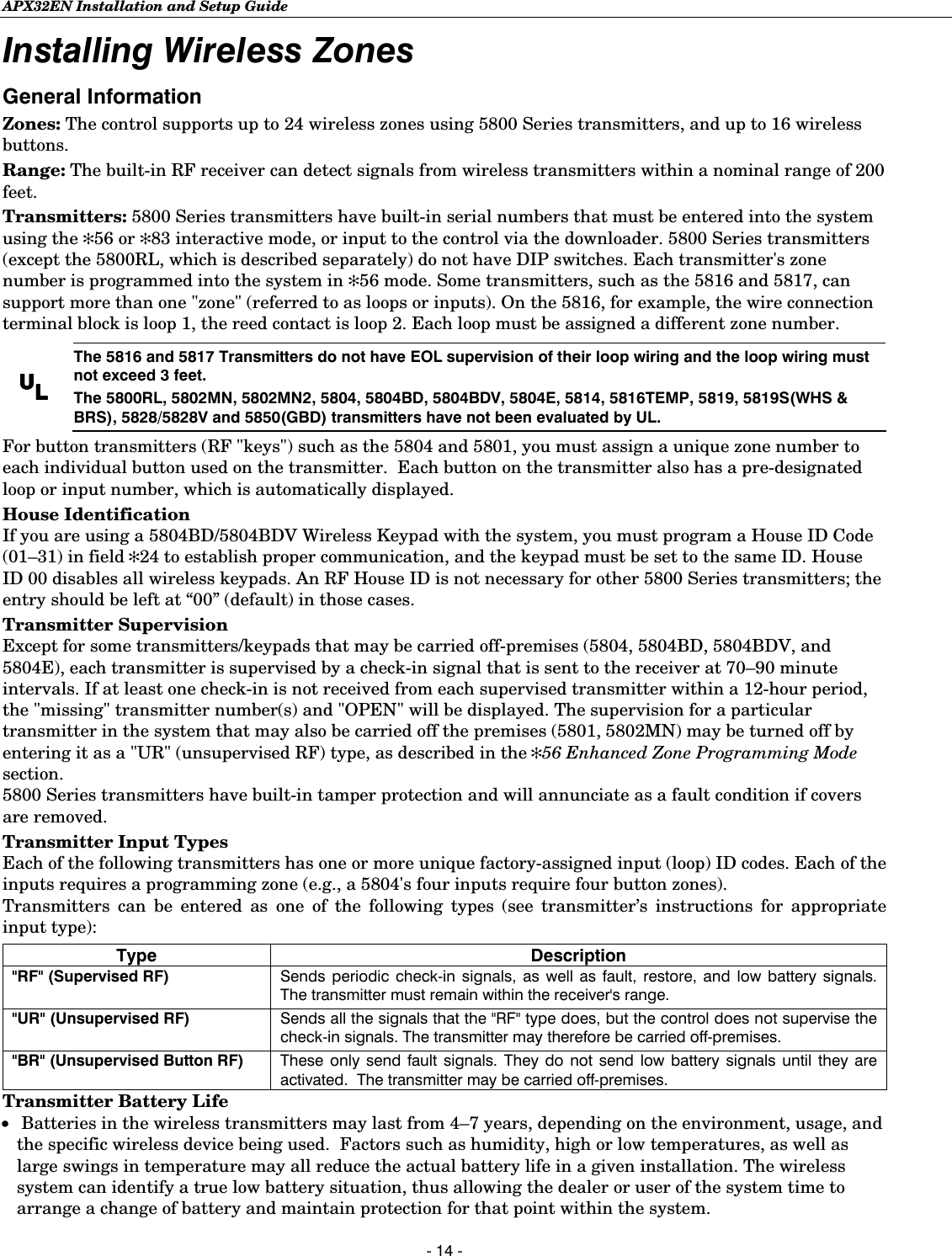
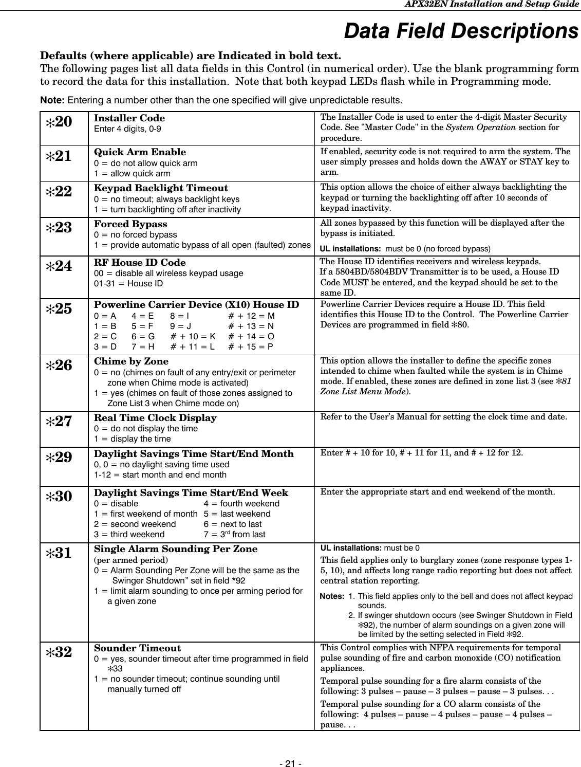
![APX32EN Installation and Setup Guide - 17 - Mechanics of Programming General Programming Information Programming options are stored in non-removable, electrically erasable, nonvolatile EEROM memory. The system can be programmed at any time, even at the installer's premises prior to the actual installation. Simply apply power temporarily to the Control and then program the unit as desired. There are four programming modes: • Data field programming (used for setting various system options). • Interactive menu mode programming (used for programming zone information, programming Powerline Carrier Devices, and for entering transmitter serial numbers). • Voice Prompt programming (used for setting various system options). • Pass-Thru programming (used for programming connected LRR/IP Communications Device). The system can also be programmed remotely, using an IBM Personal Computer and Compass Downloader and modem or via capable GSM or IP communications modules. See the Remote Programming/Control (Downloading) section. Note: You may find it convenient to adjust the volume setting before entering the Program Mode. This will allow you to clearly hear the feedback announcements or system beeps in the Programming Mode, of the system’s built-in speaker. To adjust the volume, press FUNCTION + VOLUME+ [3] or [6]. Upon exiting the Program Mode, the system will reset the volume to the default value (mid level). Entering Program Mode Use one of the following methods to enter Programming Mode: 1. Press both the [✻] and [#] keys at the same time, within 50 seconds after power is applied to the Control or from exiting Programming mode, OR 2. After power-up, enter the Installer Code (4112) + 800 to enter Expert Programming mode (This method disabled if Program mode is exited using ✻98). OR enter Installer Code (4112) + 888 to enter Voice Prompt Programming mode. If a different Installer Code has been programmed, use that code to enter the Programming mode. 3. Upon entering programming mode, the control will display “--” for up to two seconds indicating it is communicating with the LRR/IP devices. 4. Once you have entered the Program mode, data field “20” (the first data field in the system) will be displayed and both keypad LEDs will flash. If you have entered the Voice Prompt Programming mode. “Pro” will be displayed. Programming a Data Field 1. Press [✻] + Field No. (for example, ✻21), followed by the required entry. 2. When you have completely programmed a data field, the keypad will “beep” three times and then automatically display the next data field in sequence. To go to a different field, press [✻] plus the desired field number. 3. If the number of digits that will be entered in a data field is less than the maximum number of digits available (e.g. phone number field), enter the desired data, then press [✻] to advance to the next data field. 4. If a nonexistent field has been entered, the keypad will display “EE”. Simply re-enter [✻] plus a valid field number. To view a data field without making changes: Enter [#] + Field No. Data will be displayed for that field. To delete an entry in a field: Enter [✻] + Field No. + [✻]. (Applies only to fields ✻40–✻44, ✻88 and ✻94).](https://usermanual.wiki/Ademco/8DLLYNXREN-6/User-Guide-883200-Page-17.png)
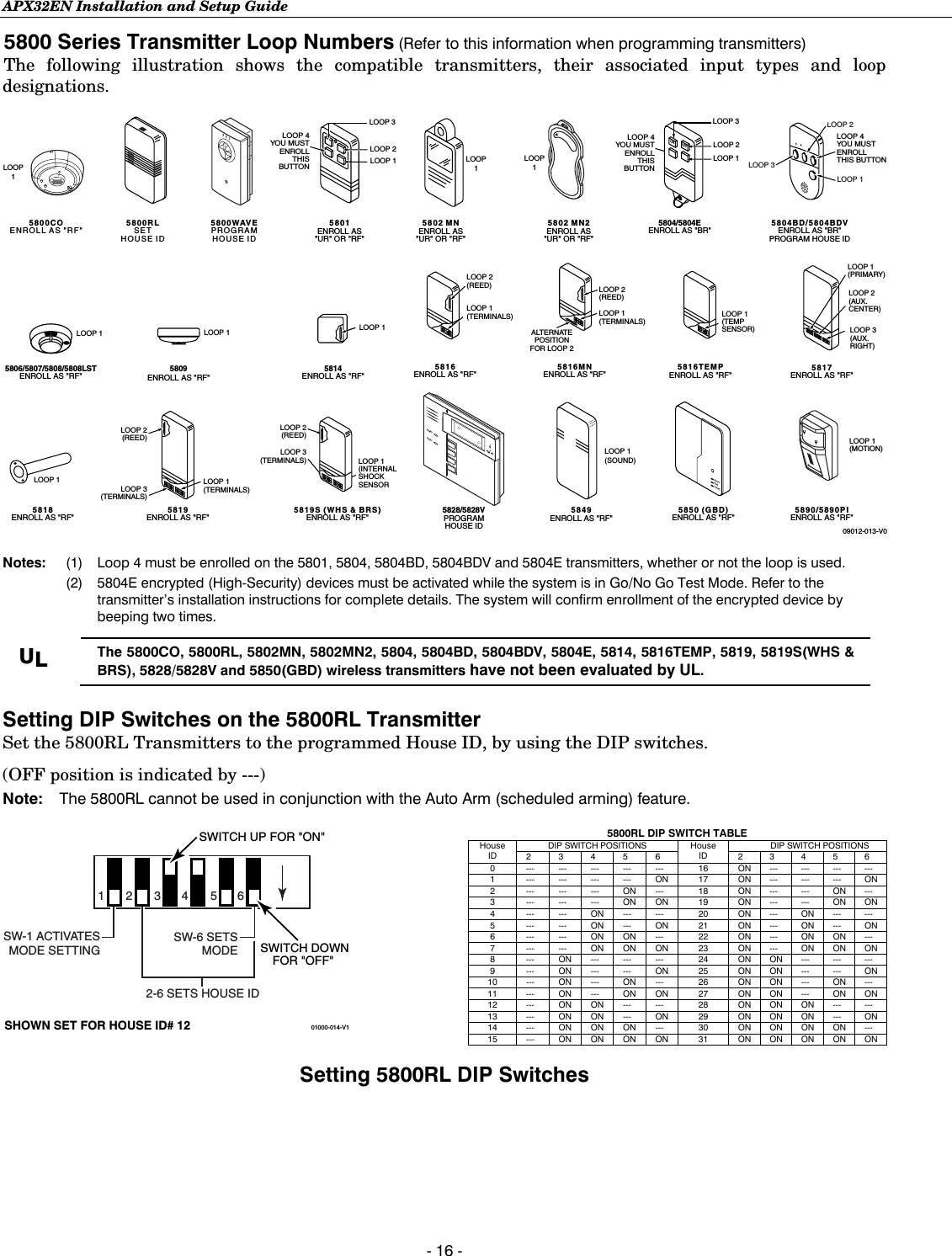
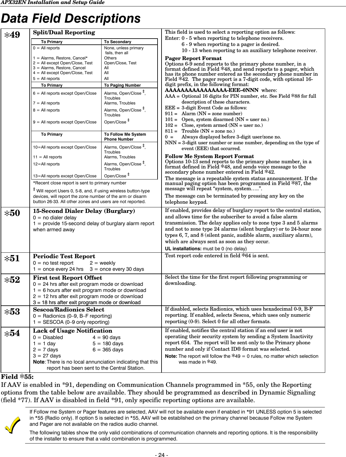
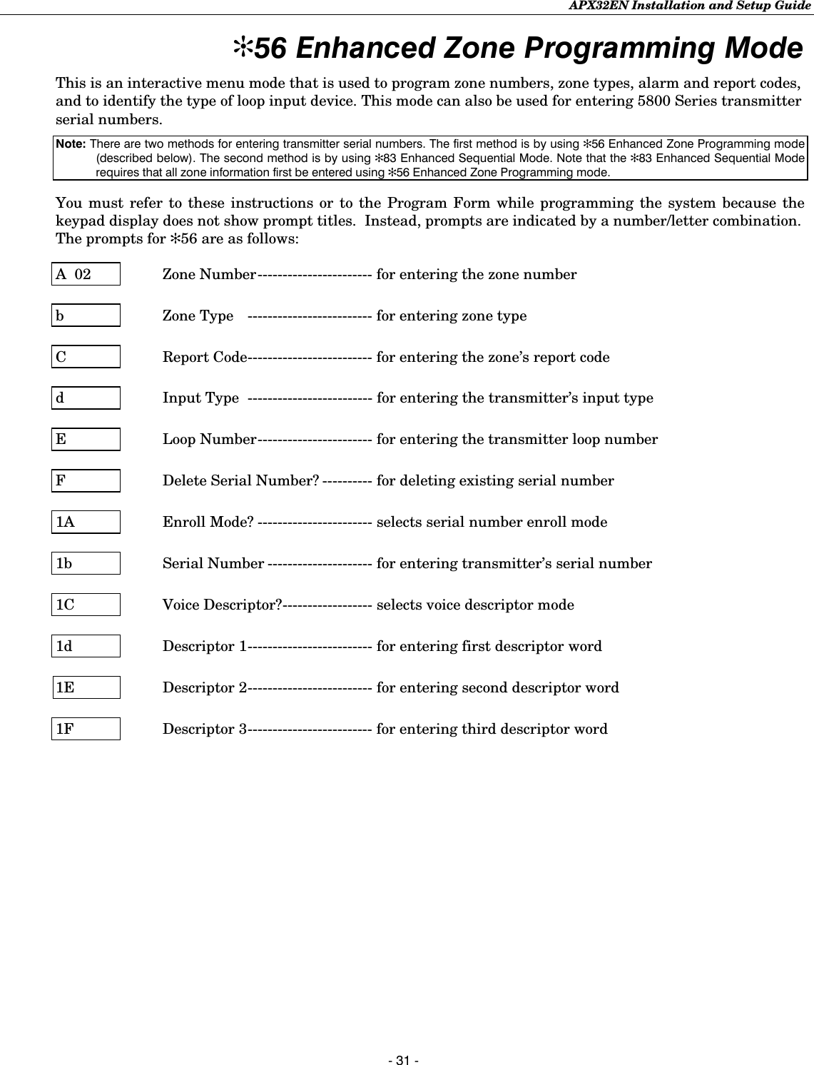
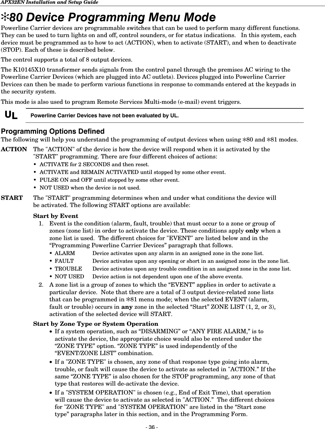
![APX32EN Installation and Setup Guide - 18 - Interactive Menu Mode Programming (✻56, ✻80, ✻81, ✻83, ✻84, ✻85) Press [✻] + interactive mode No. (i.e., ✻56). The keypad will display the first of a series of prompts. A detailed procedure (with displays of prompts) is provided in later sections of this manual. Interactive Mode Used to Program ✻56 Enhanced Zone Programming Mode Zone characteristics, report codes, and serial numbers ✻80 Device Programming Menu Mode Powerline Carrier Devices ✻81 Zone List Menu Mode Zone Lists for powerline carrier activation ✻83 Enhanced Sequential Mode 5800 Series transmitter serial numbers ✻84 Assign Zone Voice Descriptors Voice descriptors for each zone ✻85 Record Custom Voice Descriptors Up to 5 custom voice descriptors for zones Loading Factory Defaults To load the factory defaults, enter the Programming mode, press ✻97, then press number 1, 2, 3, or 4 to select from default tables 1-4 at the back of this manual, or press “0” if you are not selecting a default table. If a default table is loaded, any data that has already been programmed into the system will be changed according to the default table selected! ✻96 resets all subscriber account numbers and CSID in preparation for an initial download. Exiting Program Mode ✻98 inhibits re-entry into the Expert or Voice Prompt Programming modes using the Installer Code. ✻99 allows re-entry into the Expert Program mode using Installer Code (4112) + 800 or into the Voice Prompt Programming mode using Installer Code (4112) + 888. Note: After exiting program mode (or upon power-up), the system takes up to a minute to reset. To bypass the reset delay, press [#] + [0]. Pass-Thru Programming This mode allows the Installer to use the APX32EN keypad and display to program the communications device that is connected to the APX32EN. Refer to the communications device’s installation instruction to determine whether this feature is supported. Entering Pass-Thru Programming mode 1. After power-up, enter the Installer Code (4112) + 899. 2. Once you have entered Pass-Thru Programming mode “PtP” will be displayed on the keypad. 3. Refer to the Installation Instructions for the LRR/IP Communications Device being installed for additional programming information. APX32EN will abort this mode: • When it receives an abort command from the new communications device. • If it fails to communicate with a communications device after 20 attempts. • 30 minutes after the last key has been pressed.](https://usermanual.wiki/Ademco/8DLLYNXREN-6/User-Guide-883200-Page-18.png)
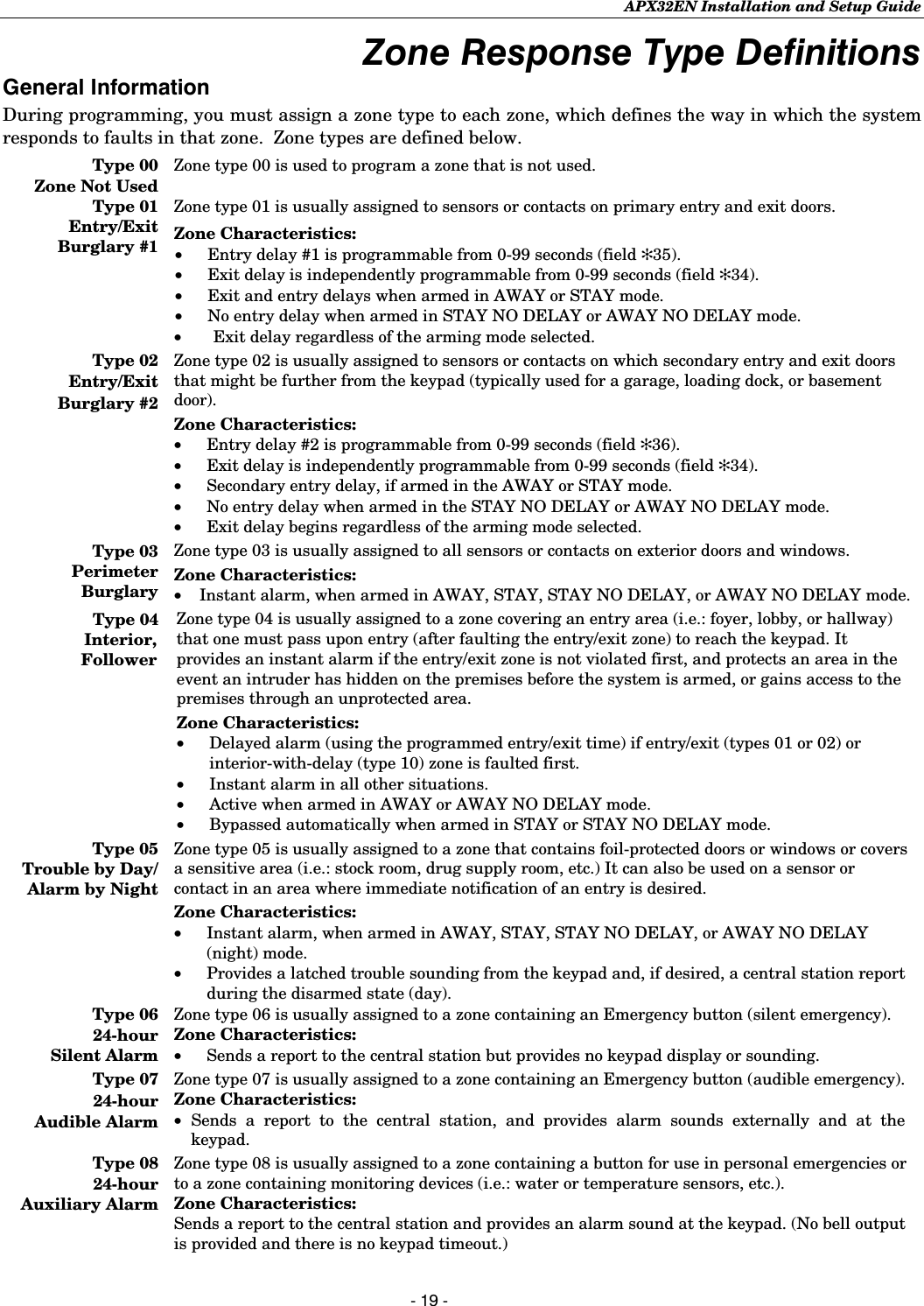
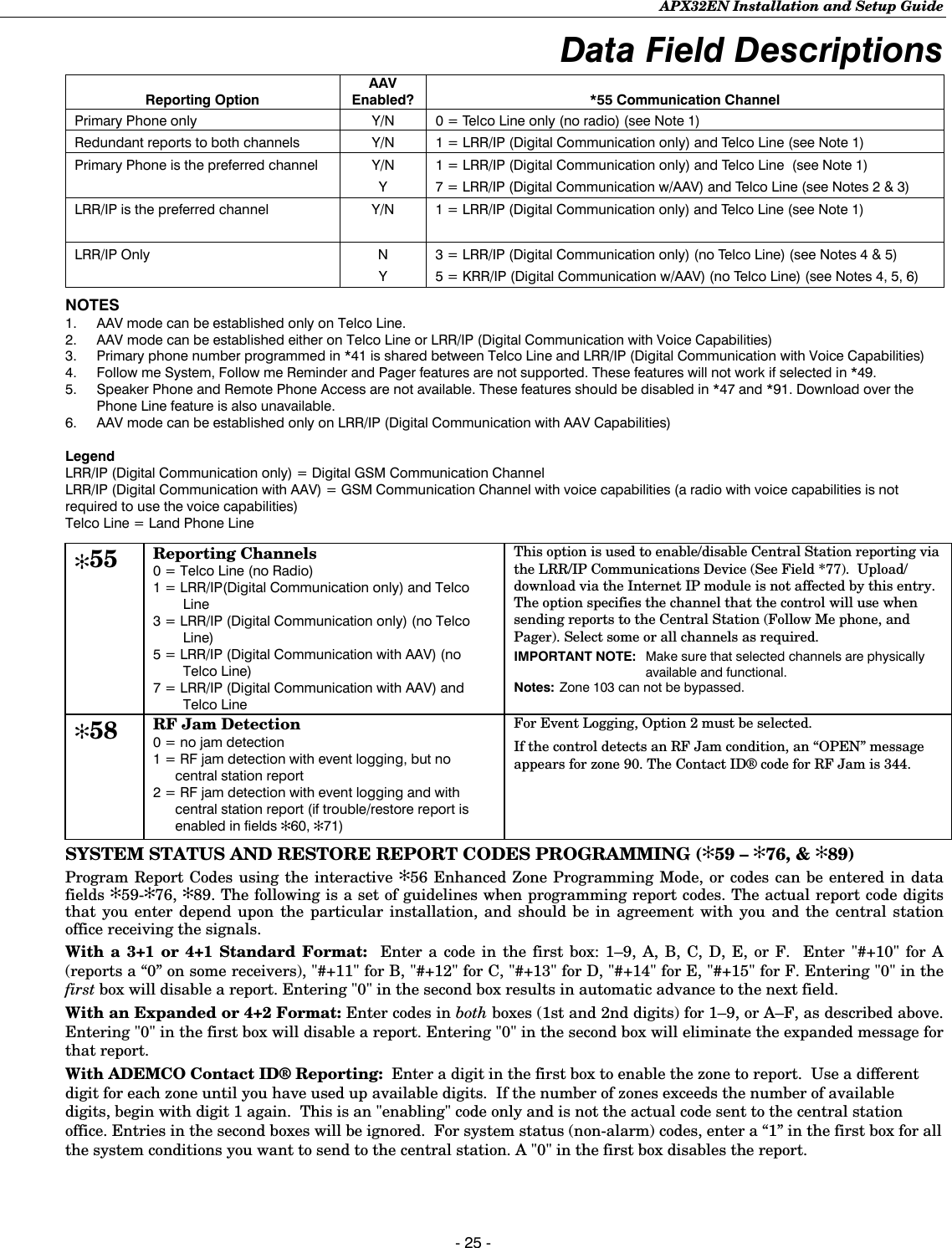
![APX32EN Installation and Setup Guide - 22 - Data Field Descriptions ✻33 Alarm Bell Timeout 0 = No timeout 2 = 8 min 4 = 16 min 1 = 4 min 3 = 12 min This field determines whether the external sounder will shut off after time allowed, or continue until manually turned off. UL installations: must be set for a minimum of 4 min (option 1) DELAY PROGRAMMING (✻34–✻36) NOTE: The control validates the data entered in these fields. If the selection is not valid the control will emit a single long beep indicating that the selection has been rejected. The control replaces the selection with the default value which is displayed on the keypad. ✻34 Exit Delay 00-99 = exit delay time in seconds The system will wait the time entered before sounding an alarm if the exit door is left open after the system has been armed. UL installations: must be set for a maximum of 60 seconds ✻35 Entry Delay 01 00-99 = entry delay time in seconds. The system will wait the time entered before sounding alarm upon entering if system is not disarmed. UL installations: must be set for a maximum of 45 seconds ✻36 Entry Delay 02 00-99 = entry delay time in seconds. The system will wait the time entered before sounding alarm upon entering. UL installations: must be set for a maximum of 45 seconds ✻37 Audible Exit Warning/Quick Exit Exit Warning Quick Exit 0 = no exit warning sound 0 = no quick exit 1 = provide exit warning sound when armed AWAY 1 = allow quick exit Exit Warning: Sound consists of slow continuous beeps until last 5 seconds, when it changes to fast beeps. The warning sound will end at the termination of exit delay. Quick Exit: If enabled, user can restart the exit delay time after arming in STAY mode by entering the user code and pressing the STAY key, or by pressing the STAY key if Quick Arm is enabled. This avoids having the user disarm then re-arm the system after allowing someone to enter or exit ✻38 Confirmation of Arming Ding 0 = no ding 1 = confirmation ding after arming system 2 = confirmation ding after arming from RF button or RF keypad only Confirmation of arming is provided by a 1/2 second external sounder “ding” that sounds when closing report is sent, or at the end of exit delay. If Option 2 is selected the external sounder “ding” occurs immediately after the system receives the RF transmission. ✻39 Power Up In Previous State 0 = always power up in a disarmed state 1 = assume the system status prior to power-down When the system powers up armed, an alarm will occur 1 minute after arming if a zone is faulted, and any bypassed zones will be unbypassed. Note: If the previous state was armed AWAY or STAY, the system will not respond to sensor changes for 1 minute, which allows time for sensors such as PIRs to stabilize. UL installations: must be 1 (power up in previous state) DIALER PROGRAMMING (✻40–✻50) Fields ✻40, ✻41, ✻42: Enter up to the number of digits shown. Enter 0–9, # + 11 for ‘✻’; # + 12 for ‘#’; # + 13 for a pause (2 seconds) NOTES: Whenever AAV is used, primary (field ✻41) and secondary (field ✻42) phone numbers should be preceded with the call waiting disable command. Otherwise, there is the possibility of connection of the third party to APX32EN during AAV mode. The PABX phone number entered in field ✻40 is not dialed on GSM/IP (Digital Communication with AAV). However, it is used for dialing on Telco Line line. ✻40 PABX Access Code Enter up to 6 digits if PABX is needed to access an outside line. If fewer than 6 digits need to be entered, exit by pressing [✻]. To clear entries from field, press ✻40✻. If the GSM/IP (Digital Communication with AAV) feature is used (options 5 and 7 in *55), there may be restrictions when dialing the numbers entered in *41, *42 and *46 (i.e.; #, ✻, pause may not be allowed, or phone number extensions may not be dialed, etc) depending on the service provider. ✻41 Primary Phone No. Enter up to 20 digits. If fewer than 20 digits entered, exit by pressing [✻]. To clear entries from field, press ✻41✻. Note: Backup reporting (8 attempts are made to the secondary phone number if no kissoff is received after 8 attempts to the primary number) is automatic only if there is a secondary phone number (field ✻42).](https://usermanual.wiki/Ademco/8DLLYNXREN-6/User-Guide-883200-Page-22.png)
![APX32EN Installation and Setup Guide - 23 - Data Field Descriptions ✻42 Secondary Phone No. Enter up to 24 digits. If fewer than 24 digits entered, exit by pressing [✻]. To clear entries from field, press ✻42✻. See backup reporting note for field ✻41. If using the paging feature, enter the pager phone number here. All four digits of the Subscriber Account number must be entered in Fields ✻43 and ✻44. If ten-digit format is selected in ✻48 (option 5), all ten digits of the Subscriber Account number must be entered. Fields ✻43 and ✻44: Enter [✻] as the fourth digit if a 3-digit account number (for 3+1 dialer reporting format) is used. Enter 0 as the first digit of a 4-digit account number for Nos. 0000–0999. Enter [✻] as the fifth digit if a 4-digit account number (for 4+1, 4+2 CID®) is used. Exit field by pressing [✻] if only 3 digits are used. To clear entries from field, press ✻43✻ or ✻44✻. See blank Programming Form for examples of account number entries. If using the paging feature, do not enter a leading 0 in the subscriber account number, and do not use digits A-F anywhere in the number. Some paging systems provide voice mail capability, which is activated by a leading 0 in the message. Enter digits 0–9; # +11=B; # +12=C; # +13=D; # +14=E; or # +15=F. ✻43 Primary Subs Account No. Enter a four or ten digit account number. Enter the primary subscriber account number. To clear entries from field, press ✻43✻. ✻44 Secondary Subs Account No. Enter a four or ten digit account number. Enter the secondary subscriber account number. To clear entries from field, press ✻44✻. Field 46: Enter up to 24 digits. Do not fill unused spaces. Enter 0-9, #+11 for ‘*’; #+12 for’#’; #+13 for a pause (2 seconds). ✻46 “Follow Me Reminder” Phone Number Enter up to 24 digits. This option allows the user to schedule a time driven message. When activated the system will dial the phone number programmed and deliver a voice message (custom words 72, 73 and 74). This option is only supported when the pager or follow me feature is enabled in field ✻49 (option 6-9 or 10-13). If using the Follow Me Reminder feature, enter the phone number here. If fewer than 24 digits are entered, exit by pressing [✻]. To clear entries from the field press ✻46✻. The telephone message can be terminated (acknowledged) by pressing any key on the telephone keypad. Pressing any key on the local APX32EN keypad will terminate (acknowledge) both the follow me and the local reminder announcements. Note: The follow me reminder announcement will be terminated if any other event requires the system to dial out or if an audible alarm has occurred. ✻47 Phone System Select Central Dialing Mode Station Pulse Tone Pulse Tone No WATS 0 = No Speaker Phone 1 = No Speaker Phone 4 = With Speaker Phone 5 = With Speaker Phone WATS 2 = No Speaker Phone 3 = No Speaker Phone 6 = With Speaker Phone 7 = With Speaker Phone This option is used to enter the correct type of phone dialing (pulse or tone), and to select the correct WATS line option for the Central Station. This option is used to activate the Speaker Phone option. Note: If using pulse dialing, you must enter the numbers slowly in order to allow the pulse dialer time to operate. ✻48 Report Format for Primary/Secondary Primary Secondary See choices below See choices below 0 = 3+1; 4+1 ADEMCO Low Speed Standard 1 = 3+1; 4+1 Radionics Standard 2 = 4+2 ADEMCO Low Speed Standard 3 = 4+2 Radionics Standard 5 = ADEMCO Contact ID® Reporting with 10-digit subscriber account number 6 = 4+2 ADEMCO Express 7 = ADEMCO Contact ID® Reporting with 4-digit subscriber account number 8 = 3+1; 4+1 ADEMCO Low Speed Expanded 9 = 3+1; 4+1 Radionics Expanded Enter ✻ as the 4th digit of ✻43 through ✻44, if 3+1 dialer reporting is to be used. (For an explanation of these formats, see the System Communication section of this manual.) Notes: (1) The maximum number of alarm and alarm restore reports during one armed period is determined by field ✻92. (2) If Option 5 is selected a 10-digit account number must be entered in Fields ✻43 or ✻44. (3) Option 5 or 7 (ADEMCO Contact ID® Reporting) must be selected for AAV.](https://usermanual.wiki/Ademco/8DLLYNXREN-6/User-Guide-883200-Page-23.png)
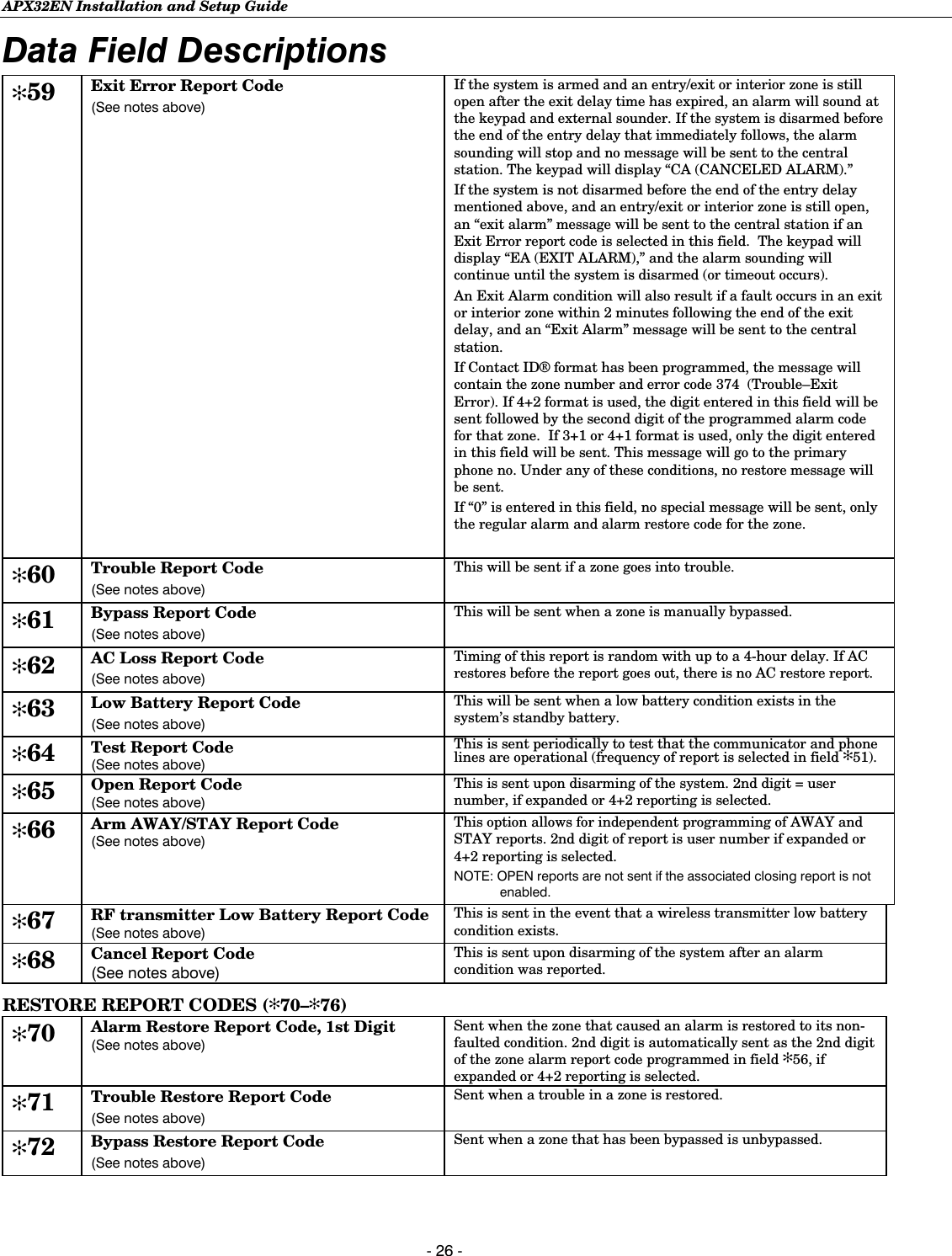
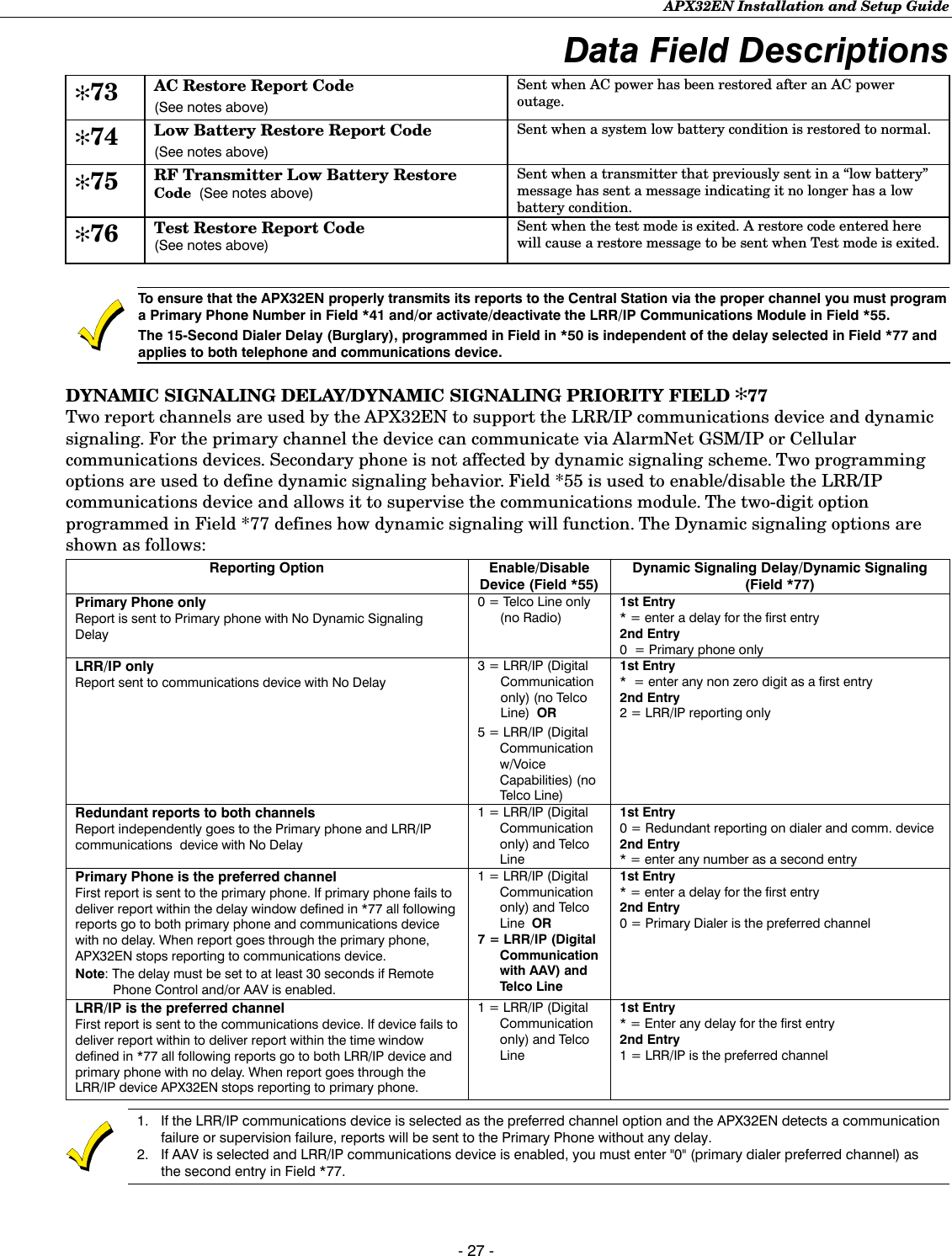
![APX32EN Installation and Setup Guide - 28 - Data Field Descriptions ✻77 Dynamic Signaling Delay/ Dynamic Signaling Priority 1st Entry (delay before switching Central Station reporting path) 0 = Redundant reporting on dialer and LRR/IP communications device 7 = 105 seconds 8 = 120 seconds 9 = 135 seconds #10 = 150 seconds 1 = 15 seconds #11 = 165 seconds 2 = 30 seconds #12 = 180 seconds 3 = 45 seconds #13 = 195 seconds 4 = 60 seconds #14 = 210 seconds 5 = 75 seconds #15 = 225 seconds 6 = 90 seconds 2nd Entry 0 = Primary Dialer Preferred Channel 1 = LRR/IP Preferred Channel 2 = LRR/IP reporting only Intended for use with LRR/IP communication device reporting. This field’s 1st Entry allows you select the time-out period the panel will wait for acknowledgment from the first reporting destination (preferred channel) before it attempts to send a message to the second destination. This delay is per message. The 2nd entry allows you to select the (Dynamic Signaling Priority) preferred reporting channel. Notes: (1) You must also enable/disable LRR/IP Device in field *55. (2) If Remote Phone Access is enabled, and Primary Phone is used as a Preferred Channel, Dynamic Signaling Delay should be at least 30 sec in order to prevent duplicate reports. (3) For UL installations Dynamic Signaling Delay cannot exceed 15 sec. If Primary Phone is used as a Preferred Channel, duplicate reports may sent. 1st Entry Enables Dynamic Signaling Delay. The entry of digits 1-9 or #10-#15. Delays can be selected from 0 to 225 seconds, in 15-second increments. If 0 is entered, the control panel will send redundant reports to both Primary Dialer and the LRR/IP communications device. 2nd Entry The second entry determines the alternate Central Station com-munication path that will be initiated after the time-out period. ✻78 Programmable Tone Generation Time 0 = Disabled 1-9 = 100-900 ms 10-99 = 1.0 – 9.9 secs. This field is used to set the time delay between when a connection is established on a Radio (digital communication with voice capabilities) session to when the 2100 Hz “training” tone is terminated. Enter any digit between 0 and 99. Note: This field only applies when a GSMV radio is installed in the APX32EN. Otherwise, enter “0” to disable. ✻86 Multi-mode (E-mail notification) 0 = Disable multimode devices 1 = Enable multimode device address #6 only 2 = Enable multimode device address #7 only 3 = Enable multimode addresses #6 & #7 Enable if using AlarmNet Remote Services e-mail notification (multi-mode) feature. The address(es) used must also be enabled in the AlarmNet communication device. For more information refer to the instructions provided with the Communications Device being installed. ✻87 AUX Function/1-Button Paging 0 = Aux key performs defined function (macro) 1 = Aux key sends predefined message to pager or a voice message to Follow Me system phone number If “0” is entered, user can define a macro function for the AUX key. See user manual for description of the use of this key. If “1” is entered, you must also select an option in field ✻49. The options are 6-9 for the pager or 10-13 for the follow me system announcement. The actual pager message is 999-9999. Note that the hyphen may not be displayed, depending on the pager service. The manual follow me system announcement is a repeatable “System, System…..”. Note: A macro cannot be run from the Test mode. ✻88 Pager Characters Enter up to 16 digits that will appear in front of the 7-digit pager message. Enter [#] + [11] for “*” Enter [#] + [12] for “#” Enter [#] + [13] for 2-second pause Note: Verify that the pager supports [*] and [#] characters before using them. Some pagers require an additional delay [pause] in order to receive the entire message. If entered, these digits will appear in front of the 7-digit pager message sent by the control (either upon a system event or upon pressing the AUX key [if programmed for paging]), and during latch key report (if enabled during scheduling). These digits can consist of a PIN number, account number, pauses or special digits needed by the pager (these types of characters are not displayed), or any other characters the user chooses that will be displayed (e.g., using a character code to distinguish between control panel messages and other pager messages). You do not need to fill all 16 digits. Press [✻] + next field number to exit the field. To clear the field, press ✻88✻. See field ✻87 to select the AUX key Paging feature. See field ✻49, which must have an option 6-9 selected to enable paging messages, for description of the pager message. ✻89 Event Log 80% Full Report Code (See notes above) If an Event Logging selection is made in field ✻90, a message can be sent to the central station receiver when the log is 80% full. If the log becomes full, a new message will overwrite the oldest message in the log. Note: All control and readout from the log, aside from the selection made by the installer in field ✻90, is accomplished via the downloader.](https://usermanual.wiki/Ademco/8DLLYNXREN-6/User-Guide-883200-Page-28.png)
![APX32EN Installation and Setup Guide - 29 - Data Field Descriptions ✻90 Event Logging Options 0 = No event logging 1 = log Alarm/Alarm Restore 2 = log Trouble/Trouble Restore 4 = log Bypass/Bypass Restore 8 = log Open/Close x = log combination of events (add value of entries) Example: To select “Alarm/Alarm Restore” and “Open/Close,” enter 9 (1 + 8); to select all events, enter #15. Default “3” = alarm/alarm restore (1) plus trouble/trouble restore (2). The system has the ability to record various events in a history log (84-event capacity). The types of events to be logged can be selected as indicated. At any time, the downloader operator can then upload the log and view or print out all or selected categories of the log. The log can also be cleared by the download operator. The display/printout at the central station will show the date, time, event, and description of the occurrences. Note: System messages are logged when any non-zero selection is made. ✻91 Audio Alarm Verification (AAV)/Remote Phone Control 0 = none 1 = AAV and remote phone control 2 = remote phone control only 4 = AAV only Notes:(1) For UL installations Audio Alarm Verification cannot be used. Audio Alarm Verification will only function when Contact ID® is selected. (2) AAV and Remote Phone Control features can only be used if the central station or remote phone supports DTMF commands. This option is used to enable the Audio Alarm Verification and/or the Remote Phone Control features. Notes: (1) In order to activate the Remote Phone Control feature and defeat an answering machine, ensure that the correct ring detection count (“15”) has been programmed in field ✻95. (2) Remote phone session will be terminated if a report must be sent. (3) Alarm Audio Verification will only function when Contact ID® is selected. AAV cannot be used for UL installations. (4) If an alarm will be reported to primary and secondary phone numbers, AAV can only function via the secondary number. (5) If an alarm will be reported to a pager (6-8 in field ✻49), or to follow me phone number (10-12 in field ✻49) AAV cannot be used. (6) If AAV is selected and LRR/IP communications device is enabled, you must enter "0" (primary dialer preferred channel) as the second entry in Field *77. ✻92 Number of Reports In Armed Period 0 = reports limited to a total of 10 1 = unlimited number of reports This option can be used to limit the number of messages (alarm & alarm restore reports) sent to the central station in an armed period. UL installations: must be 1 (unlimited reports) ✻93 Flexible Callback 0 = no flexible callback 1 = last digit flexible 2 = last 2 digits flexible 3 = last 3 digits flexible Note: This feature only applies to telephone downloading If enabled, the control will ignore the last 1, 2, or 3 digits of the programmed callback number (field ✻94) during a single download session. This allows the download operator to temporarily change the callback phone number by the number of digits selected, which allows the control to call back similar, but different numbers during a single session. For example, if downloading to a large number of controls, the operator can command the controls to call back phone numbers 555-1111, 555-1112, 555-1113, etc., thus spreading the communications among several computers. DOWNLOAD INFORMATION (✻94, ✻95) ✻94 Download Call Back Phone Number Enter up to 20 digits as follows: 0–9, # +11 for “*”, # + 12 for “#”, # + 13 for a pause. This is the phone number the control will use to call back the downloading computer. Do not fill unused spaces. End field by pressing ✻. To clear entries from field, press ✻94✻. ✻95 Ring Detection Count For Downloading/ Remote Phone Control 0 = disable station initiated download and remote phone 1-14 = number of rings before control picks up phone line 15 = defeat answering machine Enter “15” to select defeat answering machine mode. If an answering machine is on the premises, you need to dial the premises and hang up on the first ring. Wait at least five (5) seconds (but no more than 22 seconds) and dial the premises phone number again. The control will pick up and announce “SYSTEM ENTER CODE” every three seconds. Note: To enter a number higher than 9 you must first press the [#] key.](https://usermanual.wiki/Ademco/8DLLYNXREN-6/User-Guide-883200-Page-29.png)
![APX32EN Installation and Setup Guide - 30 - Data Field Descriptions OTHER PROGRAMMING COMMANDS ✻56 ENHANCED ZONE PROGRAMMING MODE Interactive menu mode used for programming zone attributes and report codes. Refer to the ✻56 Enhanced Zone Programming Mode section for procedure. ✻80 DEVICE PROGRAMMING MENU MODE Interactive menu mode for programming Powerline Carrier Devices. Refer to the ✻80 Device Programming Menu Mode section for detailed procedure. ✻81 ZONE LISTS MENU MODE Interactive menu mode for programming zone lists for Powerline Carrier Devices. Refer to the ✻81 Zone List Menu Mode section for detailed procedure. ✻83 ENHANCED SEQUENTIAL MODE Interactive menu mode used to enter RF transmitter serial numbers. Refer to the ✻83 Enhanced Sequential Mode section for detailed procedure. ✻84 ASSIGN ZONE VOICE DESCRIPTORS Interactive menu mode used to assign descriptors to each zone. These descriptors will be announced whenever the system announces an event involving a zone. ✻85 RECORD CUSTOM VOICE DESCRIPTORS Interactive menu mode used to record custom descriptors for use with each zone. ✻96 INITIALIZE DOWNLOAD ID AND SUBSCRIBER ACCT. NO. FOR DOWNLOADING Pressing ✻96 initializes the system for downloading. ✻97 SET ALL PROGRAM FIELDS TO 1 OF 4 SETS OF DEFAULT VALUES See Default Tables at the end of this manual. ✻98 EXITS PROGRAMMING MODE Prevents re-entry by: Installer Code + 8 + 0 + 0; allows re-entry only by Power-up, then [✻] and [#]. ✻99 EXITS PROGRAMMING MODE Allows re-entry to program mode by: Installer Code + 8 + 0 + 0; or by Power-up, then [✻] and [#].](https://usermanual.wiki/Ademco/8DLLYNXREN-6/User-Guide-883200-Page-30.png)
![APX32EN Installation and Setup Guide - 32 - ✻56 Enhanced Zone Programming Mode While in Program mode, press ✻56 to enter Zone Programming Menu Mode. Refer to the zone assignment table for ✻56 on the separate programming form. The following explains the ✻56 prompts in detail. The left two columns identify the prompts and list the available entries for each. The right-most column provides a further explanation of the entries. Note: You may find it convenient to adjust the volume setting before entering the Programming Mode. This will allow you to clearly hear feedback announcements or system beeps. A 02 Zone number 02-41, 95, 96, 99 = Zone number [✻] = continue 00 = exit Zone Programming mode Enter the 2-digit zone number to be programmed and the Voice Descriptor for the selected zone number will be announced, if it is programmed. Press [✻] to advance. • Zones 02-25 = RF zones (only) • Zones 26-41 = Button zones (only) • Zone 92 = Duress • Zones 95, 96, 99 = Panic zones Pressing 00 exits mode, upon which the prompt “56” blinks, indicating the mode is inactive. Press [✻] + any field number to go to that field. b zt Zone type 00-24 = zone type [✻] = continue [#] = return to previous prompt Note: If 00 is accepted as a zone type, save the 00 zone type and advance to the confirm delete prompt (F). Each zone must be assigned to a zone type, which defines the way in which the system responds to faults in that zone. Enter the 2-digit zone type for this zone as follows: 00 = Not Used 09 = Fire without verification 01 = Entry/Exit #1 10 = Interior w/Delay 02 = Entry/Exit #2 14 = Carbon Monoxide 03 = Perimeter 20 = Arm–Stay 04 = Interior Follower 21 = Arm–Away 05 = Trouble Day/Alarm Night 22 = Disarm 06 = 24 Hr Silent 23 = No Alarm Response 07 = 24 Hr Audible 24 = Silent Burglary 08 = 24 Hr Aux C rc Report code Enter the report code for this zone. [✻] = continue [#] = return to previous prompt The report code consists of 2 hexadecimal digits, each in turn consisting of 2 numerical digits. For example, for a report code of "3C", enter [0][3] for "3" and [1][2] for "C". If this is Zone 95, 96 or 99, the system skips to the VOICE DESCRIPTOR prompt (1C). d i Input type 3 =RF (supervised RF) – sends periodic check-in signals, faults, restore and low battery signals Note: RF type transmitters must remain within range of the receiver, otherwise a supervision failure signal will occur. 4 = UR (unsupervised RF) – sends same as “RF” type, but control does not supervise the check-in signals 5 = BR (button type) – sends only fault and low battery signals; does not send restores or check-in signals Note UR and BR type transmitters may be carried off premises (out of range without causing a supervision failure. [✻] = continue [#] = return to previous prompt Enter the input type for the transmitter assigned to this zone. Refer to the transmitter’s instructions for input types of each transmitter. Note: Zones 2-25 should be assigned Input Type 3 or 4 . Zones 26-41 should be assigned Input Type 5 only.](https://usermanual.wiki/Ademco/8DLLYNXREN-6/User-Guide-883200-Page-32.png)
![APX32EN Installation and Setup Guide - 33 - ✻56 Enhanced Zone Programming Mode E l Loop number or Loop and Serial number (if using RF Learning) 1-4 = loop number for the zone of the transmitter being entered. 0 + [✻] = continue to DELETE ZONE PARAMETERS CONFIRMATION prompt (F) [✻] = continue to the ENROLL MODE prompt (1A) if not entered, or VOICE DESCRIPTOR prompt if already entered [#] = return to previous prompt This prompt can be used to enroll loop number and serial number via RF transmission or the loop number can be enrolled manually. If using the RF Learning Mode, there is no need to manually enter a loop number. Proceed directly to RF Learning Notes: (1) BR type devices cannot be enrolled by using UR or RF type. Likewise, UR or RF type devices cannot be enrolled by using a BR type device. There is a 52-second time-out for RF enrolling. At the end of the time-out, the system returns to the INPUT TYPE prompt (d). If enrolled, loop number and “L” are displayed. (2) Once encrypted (high-security) devices have been enrolled they must be activated. Refer to the device’s Installation Instructions to activate the High-Security Mode. RF Learning - Two (2) transmissions (2 key depressions) at least 5 seconds apart will be required for BR type devices (device type 5). Two beeps will sound after the second transmission, confirming that the loop number and serial number have been learned. For all other device types, four (4) transmissions are required (fault, restore and fault, restore). A single beep will sound after the second transmission confirming that the loop and serial number have been captured. Following the fourth transmission the system will confirm that the loop number and serial number have been learned and announce the Voice Descriptor for the zone, if it is programmed, followed by two beeps. Press [✻] to continue. Manual Entry - Enter the desired loop number and press [✻] to continue (see the transmitter’s Installation Instructions for specific loop designations). Note: The loop number can be changed even if the zone has already been entered. Care should be taken when using this feature as it has the capability to make zones inoperable by creating a mismatch of a working serial number/loop number combination. This should be re-confirmed if the loop number is changed. “L” indicates that the zone’s serial number has already been enrolled. F Delete zone parameters confirmation 0 = discard the delete request 1 = confirm requested delete Note: If 00 was entered as a zone type in prompt (b), 00 will be retained and system will advance to prompt (1C). This function deletes either the serial number or all zone information that is programmed for the zone. If “00” was entered in the zone type, the confirmation of the delete request will delete all information associated with the zone currently being programmed. If “0” was entered in the loop number, the confirmation of the delete request will delete the serial number of to the zone currently being programmed.](https://usermanual.wiki/Ademco/8DLLYNXREN-6/User-Guide-883200-Page-33.png)
![APX32EN Installation and Setup Guide - 34 - ✻56 Enhanced Zone Programming Mode IA LC Enroll mode 0 = advance to the VOICE DESCRIPTOR prompt (1C). Note: This will save all zone parameters. 1 = enter now and proceed to SERIAL NUMBER prompt (1b). Note: Not applicable if the serial number is already present. 2 = copy the last serial number entered into local ram. Note: If this is the 1st zone, none will be in the buffer and the panel will emit a long tone. Not valid if serial number is already present. 3 = view existing serial number. Note: Only if “L” is displayed. If “L” is not displayed, panel will emit a long beep. 9 = advance to F; delete existing serial number. Note: Only if “L” is displayed. If “L” is not displayed, panel will emit a long beep. [✻] = advance to the VOICE DESCRIPTOR prompt (1C). This will save all zone parameters. [#] = return to the LOOP NUMBER prompt (E). Note: In order for all entered parameters to be accepted, you must advance to the VOICE DESCRIPTOR prompt (1C). If “L” is displayed, the serial number for this transmitter has already been entered. It may, however, still be viewed, confirmed (only if in listen mode), or deleted. View serial number Enter “3”. Each digit will be redisplayed, and the keypad will beep once for digits 1-6, and three times for the last digit. Confirm serial number The serial number/loop number combination can be confirmed after one transmission from a BR type device or two transmissions (fault and restore) from a UR or RF type device. If a transmission is received that matches the serial number and loop number entered, the system will confirm the reception by announcing the Voice Descriptor for the zone, if it is programmed, followed by three beeps, and a “C” will appear on the display indicating the received serial number and loop number have been confirmed. No further transmissions will be received. Delete serial number The serial number can be deleted by entering “9”. If “L” is not displayed, the serial number for this transmitter has not been previously entered. You may enter the serial number manually, copy the previous serial number, return to Prompt (E) or enter the serial number later using the ✻83 Enhanced Sequential Mode. Manual entry Enter "1" to advance to Serial number prompt (1b). Copy the previous serial number Enter “2” to copy the previous serial number entered. Return to Prompt (E) Enter “#” to return to Loop Number prompt (E). Enter transmitter later Enter “0” or “✻” if you wish to enter the transmitter later, using the ✻83 Enhanced Sequential Mode described later in this manual. Notes: (1) The panel will listen only when it is in the idle loop waiting for key entry and a serial number has been entered. If a key is entered, the function must be completed and the panel will listen again. (2)A long beep indicates illegal entry or duplicate serial number/loop entry Ib Serial number Enter the transmitter’s 7-digit serial number. [#] = return to prompt 1A and reject any serial numbers entries that have been made. [✻] = return to prompt 1A, (if a valid serial number has been entered, the "L" is displayed and the serial number will be copied into EEROM from the last serial entered into the buffer.) Note: This prompt can be used only to manually enroll a serial number. RF enrollment will be rejected and the current zone descriptor will be announced, followed by a single long beep and the system will return to prompt (1A). In this mode, the transmitter serial numbers can only be entered manually. Enter the 7-digit serial number printed on the transmitter. If an incorrect digit is entered, press the [#] key to backup to prompt (1A) and start over. When all 7 digits are entered, press the [✻] key. If 52 seconds passes and no entry has been made, the system returns to prompt (1A). Notes: (1) If the serial and loop number combination is already present the keypad will emit a single long beep and the system will return to the (1A) prompt and “L” will be displayed. (2) If less than 7 digits have been entered, the keypad will emit a single long beep and return to the (1A) prompt without displaying the “L”. (3) If more than 7 digits have been entered, the first 6 digits will be saved along with the last digit that was entered (entering 123456789 yields the serial number 1234569). IC Voice descriptor 0 = skip to next zone (A) 1 = enter descriptor mode; existing descriptor for this zone will be announced Each zone can have a voice descriptor of up to 3 words that will be announced whenever the system announces status for that zone.](https://usermanual.wiki/Ademco/8DLLYNXREN-6/User-Guide-883200-Page-34.png)
![APX32EN Installation and Setup Guide - 35 - ✻56 Enhanced Zone Programming Mode Id vi Descriptor 1 Enter [#] + 2-digit vocabulary index number† of first descriptor word for this zone. 6 = accept word and advance to descriptor 2 (descriptor 2 will be announced) 8 = accept word and advance to next zone (prompt A) – entire zone descriptor will be announced Press any other key to repeat the selected word. † see ✻84 Assign Zone Voice Descriptors section for vocabulary index Use the [6] or [8] key to advance as described. To change the entered index number before pressing [6] or [8], simply press [#] + desired 2-digit vocabulary index number. If descriptor 1 is not desired, enter [#] + 99 (blank), then press [8] to return to zone number prompt. IE vi Descriptor 2 Enter [#] + 2-digit vocabulary index number† of second descriptor word for this zone. 6 = accept word and advance to descriptor 3 (descriptor 3 will be announced) 8 = accept word and advance to next zone (prompt A) – entire zone descriptor will be announced Press any other key to repeat the selected word. † see ✻84 Assign Zone Voice Descriptors section for vocabulary index Use the [6] or [8] key to advance as described. To change the entered index number before pressing [6] or [8], simply press [#] + desired 2-digit vocabulary index number. If descriptor 2 is not desired, enter [#] + 99 (blank), then press [8] to return to zone number prompt. IF vi Descriptor 3 Enter [#] + 2-digit vocabulary index number† of third descriptor word for this zone. 6 or 8 = accept word and advance to next zone (prompt A) – entire zone descriptor will be announced Press any other key to repeat the selected word. † see ✻84 Assign Zone Voice Descriptors section for vocabulary index Use the [6] or [8] key to advance as described. To change the entered index number before pressing [6] or [8], simply press [#] + desired 2-digit vocabulary index number. If descriptor 3 is not desired, enter [#] + 99 (blank), then press [8] to return to zone number prompt.](https://usermanual.wiki/Ademco/8DLLYNXREN-6/User-Guide-883200-Page-35.png)
![APX32EN Installation and Setup Guide - 37 - ✻80 Device Programming Menu Mode STOP The "STOP" programming determines when and under what conditions the device will be de-activated. The following options are available: Upon Restore of a Zone List Restore Zone List: If a "ZONE LIST" is used as the “Stop” event, the device will de-activate when all the zones in that list restore from a previous fault, trouble, or alarm condition. This will occur regardless of what is programmed to "START" the device; therefore, a "RESTORE ZONE LIST" would normally only be used when a "ZONE LIST" is used to start the device. Upon a Zone Type or System Operation Zone Type/System Operation: Instead of using a "RESTORE ZONE LIST," a specific zone (response) type or system operation action can be selected to de-activate the device. • If a specific "ZONE TYPE" is chosen, any zone of that response type that restores from a previous alarm, trouble, or fault condition will cause the device to de-activate. • If a "SYSTEM OPERATION" is chosen, that operation will cause the device to de-activate. During normal system operation, any devices may be manually started by keypad entry of: Code* + [#] + 4 + “n;” or manually stopped by keypad entry of: Code* + [#] + 7 + “n,” where “n” = the device number to be controlled. * Code is required for devices 7 and 8. For devices 1-6, code is not required. See User Manual for more information. Programming Powerline Carrier Devices While in program mode, press ✻80 to enter Output Device Menu Mode. This mode is used to program all output devices used in the system. Refer to the output device table for ✻80 on the separate programming form when programming output devices. Note: The House ID of the Powerline Carrier Devices must be entered in data field ✻25. The prompts for ✻80 are as follows: 80 Powerline Carrier Device Programming Main Menu prompt A 01 Device Number --------- for entering the device number b Device Action ------------ for defining the action the device will perform when active C Start Event Type ------- for assigning the event type to start the action d Start Zone List ---------- for assigning the zone list to start the action E Start Zone Type--------- for assigning the zone type to start the action F Stop Zone List ----------- for assigning the zone list to stop the action 1A Stop Zone Type---------- for assigning the zone type to stop the action](https://usermanual.wiki/Ademco/8DLLYNXREN-6/User-Guide-883200-Page-37.png)
![APX32EN Installation and Setup Guide - 38 - ✻80 Device Programming Menu Mode The following explains these prompts in detail. The left two columns identify the prompts and list the available entries. The right-most column provides a further explanation of the entries. Note: Entering a number other than one specified will give unpredictable results. 80 Powerline Carrier Device programming 0 = exit mode 1 = enter mode Entering “1” advances to the next prompt below. Entering “0” exits mode, upon which this prompt blinks, indicating the mode is inactive. A 0I Device number 01-08 = device number to be programmed 09-16 = Multi-mode (e-mail) event triggers [✻] = continue 00 = exit Device Programming mode Enter device numbers as 2-digit entries. b aa Device action 0 = No response 1 = Close for 2 seconds 2 = Close and Stay Closed 3 = Continuous Pulse on & off (1 sec ON, 1 sec OFF) [✻] = continue [#] = return to previous prompt Enter the 1-digit action (0-3) for the device being programmed (current action is displayed). Notes: 1. If “3” is entered (pulse), only up to 3 different devices can be pulsed if one of the devices is a siren/horn (X10 Powerhouse Security model SH10A). In addition, the siren/horn cannot be manually activated using the lights on/lights off keypad commands. 2. If using an X10 Powerhouse Security SH10A siren: • you must use device action “3.” • you must change the device action default to “3” if using default table 2 or 4 C et Start event type 0 = Not used 3 = Trouble 1 = Alarm [✻] = continue 2 = Fault [#] = return to previous promptEnter the 1-digit event type (0-3) to activate the device being programmed. A zone list must be used in conjunction with an event. If a zone type/system operation is to be used instead of an event, enter “0”. d zl Start zone list 1-3 = zone list number (to be programmed in field ✻81) 0 = zone list not used for this device [✻] = continue [#] = return to previous prompt If a zone list will be used to start the device action, enter the zone list number at this prompt. E zt Start zone type 01-58 = zone type to start this device action (select only those that are applicable) 00 = zone type not used for this device [✻] = continue [#] = return to previous prompt If a zone type or system operation will be used to start the device action, enter the appropriate 2-digit code for the device being programmed (see table that follows). Choices for zone types 00 = Not Used 07 = 24 Hr Audible 01 = Entry/Exit #1 08 = 24 Hr Aux 02 = Entry/Exit #2 09 = Fire without verification 03 = Perimeter 10 = Interior w/Delay 04 = Interior Follower 14 = Carbon Monoxide 05 = Trouble Day/Alarm Night 16 = Fire with verification 06 = 24 Hr Silent 24 = Silent Burglary Choices for system operation 20 = Arming–Stay 38 = Chime 21 = Arming–Away 52 = Kissoff 22 = Disarm. (Code + OFF) 39 = Any Fire Alarm 31 = End of Exit Time 40 = Bypassing 32 = Start of Entry Time 42 = System Battery Low 33 = Any Alarm (except ZT 08, 09, 14 or 16) 43 = Communications Failure 36 = At Bell Timeout** 58 = Duress ** Or at Disarming (which ever occurs earlier) SIA ZT 16 must be used in SIA fire applications. F zl Stop zone list 1-3 = zone list to stop this device action 0 = zone list not used [✻] = continue [#] = return to previous prompt If a zone list will be used to STOP, or restore, the device action, enter the zone list number 1, 2, or 3 (to be programmed in ✻81 mode). If not used, enter “0”. IA zt Stop zone type 01-58 = zone type to start this device action (select only those that are applicable) 00 = zone type not used for this device [✻] = continue [#] = return to previous prompt If a zone type or system operation will be used to STOP the device action, enter the appropriate 2-digit code (see the "ZT" choices listed above). If not, enter 00. The display then returns to the DEVICE NUMBER prompt (A) so that you can enter the next device number to be programmed, or enter [0][0] to end device programming.](https://usermanual.wiki/Ademco/8DLLYNXREN-6/User-Guide-883200-Page-38.png)
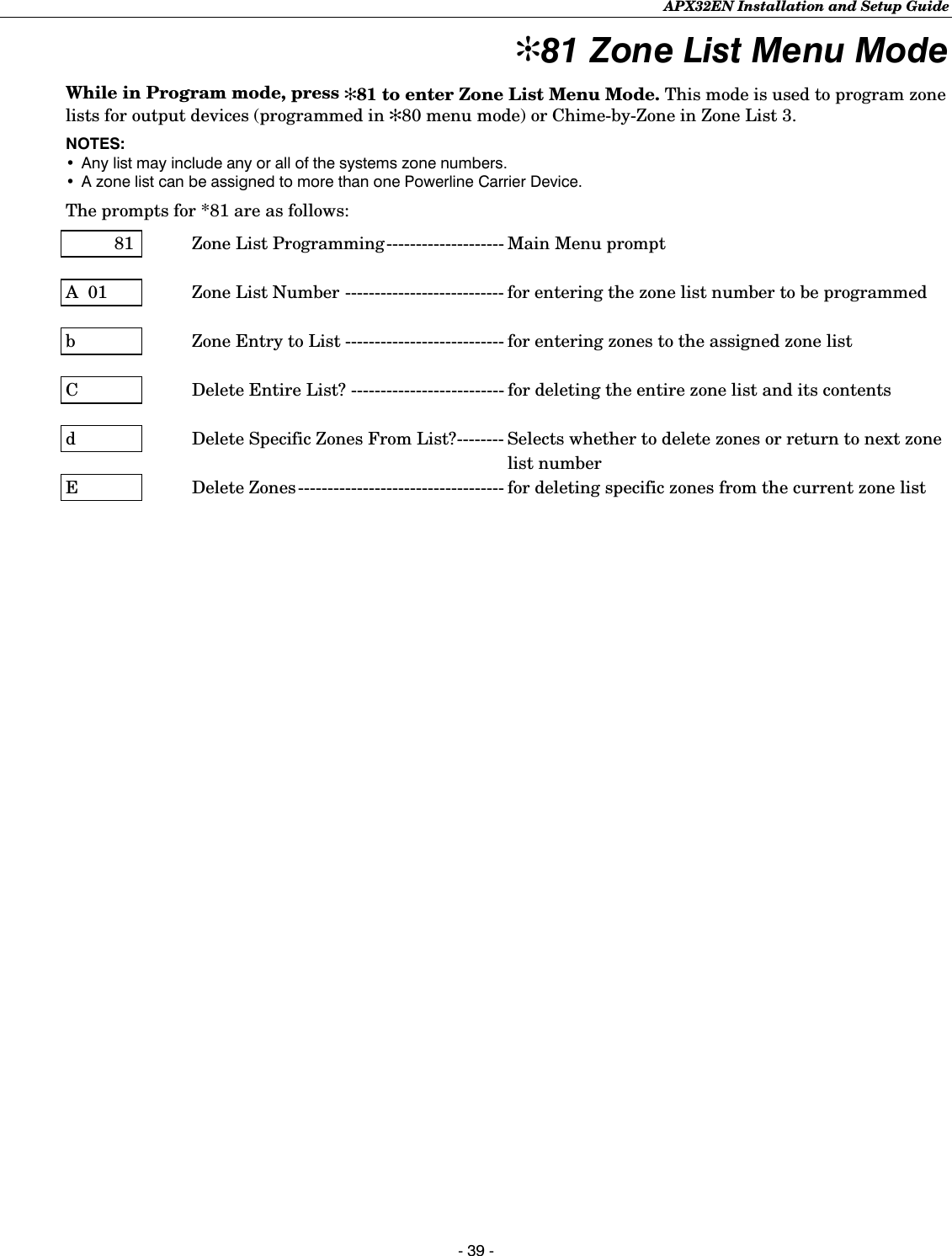
![APX32EN Installation and Setup Guide - 40 - ✻81 Zone List Menu Mode The following explains these prompts in detail. The left two columns identify the prompts and list the available entries. The right-most column provides a further explanation of the entries. Notes: (1) Entering a number other than one specified will give unpredictable results. (2) Do not assign zones with zone types 20, 21 or 22 to a zone list. (3) Zone List 2 should be used for Cross Zoning. When creating zone list 2 for cross zoning, include only 2 zones assigned to zone types 3, 4, or 5. If interior zones (zone type 4) are cross zoned, then both zones in zone list 2 must be interior zones. Do not cross zone more than 2 zones, or zone types that have delays (entry/exit zones, interior w/delay), or 24-hour zones, as these choices may produce unpredictable operation and may not function as intended. If cross zoning is used, zone list 2 should not be used for other purposes, such as triggering powerline carrier devices. If field ✻39 has been set to “0” (no cross zoning), then Zone List 2 can be used for other purposes. 8I Zone list programming 0 = exit mode 1 = enter mode Pressing 1 advances to the next prompt below. Pressing 0 exits mode, upon which this prompt blinks, indicating the mode is inactive. A 0I Zone list number 01-03 = zone list number to be programmed 00 = exit Zone List mode [✻] = continue Enter the Zone List Number 01, 02, or 03 to program (or 00 if no zone lists are used). b zz Zone entry to list 01-41, 95, 96, 99 = zone numbers to add to zone list [✻] = accept zone number and enter the next zone number 00 = accept zone number(s) and continue to next prompt Enter each zone number to add to the zone list by first entering the zone number, then the [✻] key (for example, 01✻ 02✻ 03✻). The system will announce the Voice Descriptor for the selected zone, if it is programmed. After all desired zones are enrolled, enter “00” to advance. C Delete entire zone list? 0 = don’t delete; continue to next prompt 1 = delete the current zone list To delete the zone list, enter “1”. All zones in the zone list will be deleted automatically and programming will return to the ZONE LIST NUMBER prompt. To save the zone list or delete specific zones from the list, enter “0”. d Delete zones from list? 1 = continue to delete zones prompt 0 = don’t delete; continue to next zone list number prompt (A….01) [#] = return to zone list number prompt (A….01) To save the entire zone list, enter “0” and programming will return to the ZONE LIST NUMBER prompt. To delete a zone or zones in a zone list enter “1”. E Delete zones Enter each 2-digit zone number to be deleted from the current zone list, followed by the [✻] key. [✻] = delete zone and enter next zone to be deleted 00 = delete zone and return to next zone list number prompt (A….01) desired When deleting a zone(s) from the zone list, if the selected zone has a Voice Descriptor programmed, upon deletion it will be announced as a confirmation that it has been deleted. After all zones to be deleted are entered, enter “00” to return to the ZONE LIST NUMBER prompt so that another list can be programmed, if desired.](https://usermanual.wiki/Ademco/8DLLYNXREN-6/User-Guide-883200-Page-40.png)
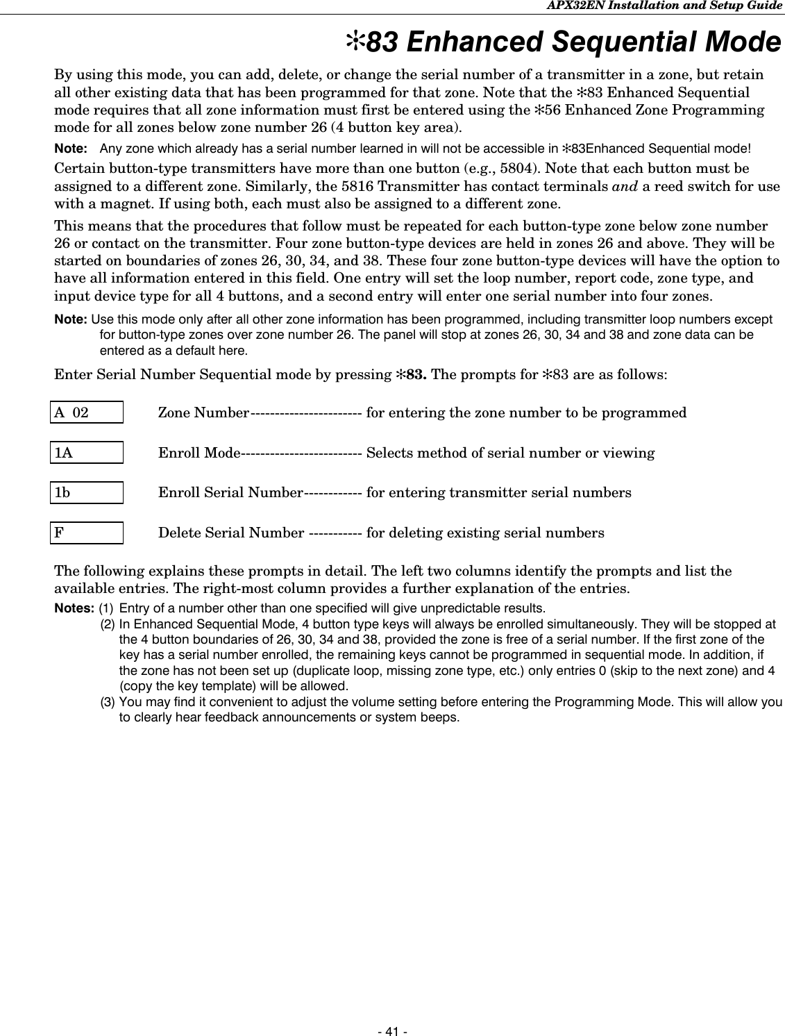
![APX32EN Installation and Setup Guide - 42 - ✻83 Enhanced Sequential Mode A 02 Zone number Enter the 2-digit zone number. [✻] = continue; system searches for zones not yet entered (for zones 2 through 25 a zone type must be entered), then advances to ENROLL SERIAL NUMBER prompt “1b” 00 = exit Sequential mode Enter the 2-digit zone number of the first transmitter to have its serial number entered. The system will announce the Voice Descriptor for the selected zone number, if it is programmed. Press [✻] to continue. Starting with this zone number, the system will search for the first transmitter that has all of the following attributes pre-programmed in ✻56 ENHANCED ZONE PROGRAMMING: a) Make sure that the appropriate input type was selected in ✻56 (RF, UR, or BR programmed) b) Make sure that the appropriate loop number was selected in ✻56. c) No serial number programmed d) Zone type If the first zone number entered does not have one or more of the above attributes, the system will search its database for the first zone that does, and will display it at the enroll SERIAL NUMBER prompt (1b). Pressing 00 exits mode, upon which the prompt “83” blinks, indicating the mode is inactive. Note: Two exceptions to the requirement above exist for keys. Four zone button type devices (zone numbers 26, 30, 34, and 38) will be stopped only if there are no serial numbers enrolled in all 4 zones of the key, regardless of the attributes that have been entered. In addition, zone types are not required to be present. In this case, 1A, Option 4 must be selected prior to “Learn”.](https://usermanual.wiki/Ademco/8DLLYNXREN-6/User-Guide-883200-Page-42.png)
![APX32EN Installation and Setup Guide - 43 - ✻83 Enhanced Sequential Mode IA zz IA LC Enroll mode 0 = advance to next zone to be enrolled 1 = enter now and proceed to SERIAL NUMBER prompt (1b). For 4 button keys (zones 26-29, 30-33, 34-37, & 38-41) the serial number will be enrolled to all four buttons. If enrolling a key, the panel will emit a long beep when entering a 1 to indicate that the present key set up is invalid. Notes:(1) A valid template or key has 4 existing zones, each with a zone type, unique loop number. (2) If the display automatically advances to "1A" rather than "1b" the configuration of the key is not valid. At that point copy template, skip, or return are the only legal entries. 2 = copy the previous serial number entry from the buffer. Notes:(1) Before you can copy a serial number you must first enter a serial number. If no serial is stored in the buffer and a copy is attempted the panel will emit a long beep indicating an invalid operation. (2) Not applicable for 4 button key zones 26-29, 30-33, 34-37, & 38-41. 3 = view existing serial number. Note: Only if “L” is displayed. If the “L” is not displayed the panel will emit a long beep. 4 = copy the 4 button key template that has been set in zone numbers 26-29 (all zone parameters except serial numbers). (Only valid on zones 30-33, 34-37, & 38-41 that do not have serial numbers enrolled.) Notes:(1) Template acceptance is indicated by two beeps after copying. (2) A single long beep emitted when copying a indicates the template is not valid. 9 = delete existing serial. Go to the (1A) prompt. For 4-button key, zones 26-29, 30-33, 34-37, & 38-41 have serial numbers. Delete all four at one time. Note: Only if “L” is displayed. If the “L” is not displayed the panel will emit a long beep. [✻] = advance to next zone to be enrolled [#] = return to previous prompt (A) Note: If “L” is displayed, the serial number for this transmitter has already been entered, however, it may still be confirmed, viewed or deleted. If the transmitter’s serial number has not been previously entered, you may enter the enroll serial number mode (1A) by entering “1”, or copy the last serial number that was entered by entering “2”. If the transmitter’s serial number has been previously entered, you may, view the present serial number by entering “3”. If view is selected each digit will be re-displayed, and the keypad will beep once for digits 1-6, and three times for the last digit. Once the serial number has been entered by either selecting a “1” or a “2”, you will return to this prompt with the “L” on the display. The serial number/loop number combination that was entered can be confirmed by getting two transmissions (fault and restore) from the RF or UR device or one transmission from the BR device. If a transmission is received that matches the serial number and loop number entered, the system will announce the Voice Descriptor for the loop followed by three beeps, and a “C” will be displayed indicating that the received serial number and loop number transmission has been confirmed to match. No further transmissions will be received. When confirming a 4 button key, only the serial number is confirmed, since it assumed that all loops are used. Pressing any key will allow a confirmation. *Long beep indicates illegal entries, or duplicate serial number/loop entry* When the last zone has been entered, the display will remain on that zone. To exit this mode and return to data field program mode, press 00 at the ZONE NUMBER prompt. When all zones have been programmed, test each zone using the system’s Test mode. Do not use the Transmitter ID Sniffer mode for this, since it will only check for transmission of one zone on a particular transmitter, and not the zones assigned to each additional loop. For Zones 26-29, 30-33, 34-37, and 38-41 any loop can be used for RF enrollment. If enrolling via RF, it will be confirmed without additional transmissions.](https://usermanual.wiki/Ademco/8DLLYNXREN-6/User-Guide-883200-Page-43.png)
![APX32EN Installation and Setup Guide - 44 - ✻83 Enhanced Sequential Mode Ib zz Ib Serial number Enter transmitter’s 7- digit serial number via RF learning or manually. [#] = return to (1A) prompt and reject whatever serial number entries have been made. [✻] = return to (1A) prompt (if a valid serial number has been enrolled, “L” is displayed and the serial number will be copied into EEROM and the last serial entered buffer. Note: For zones 26, 30, 34 and 38 only BR type devices can be used. This prompt can be used to enroll the transmitter serial number via RF transmission or manually. If using the RF Learning Mode there is no need to manually enter a serial number. Proceed directly to RF Learning. Upon entering the Serial Number mode, the Zone Descriptors will be announced. Note: BR type devices can be enrolled only by transmission from BR devices. Likewise, UR and RF devices can only be enrolled by transmission from a UR or RF device RF Learning - Two (2) transmissions (2 key depressions) at least five seconds apart, will be required for BR type or four (4) transmissions (fault, restore and fault, restore) for UR or RF type. If the learned serial number has a different loop number than that entered in ✻56 the system will announce the Voice Descriptor, if it is programmed, followed by two beeps and will return to Prompt (1A) and “L” will be displayed. If the loop number captured by RF transmission and that entered in ✻56 mode match, the system will announce the Voice Descriptor, if it is programmed, followed by three beeps and return to Prompt (1A) and “LC” will be displayed. No additional transmissions are needed for confirmation. Manual Entry - Enter the 7-digit serial number printed on the transmitter. If you enter an incorrect digit, press the [#] key to backup to prompt (1A) and start over. When all 7 digits are entered, press the [✻] key. If less than 7 digits are entered, the keypad will emit a single long beep and return to the (1A) prompt without displaying the “L”. If more than 7 digits have been entered, the first 6 digits will be saved along with the last digit that was entered (entering 123456789 yields the serial number 1234569). Note: If 52 seconds pass and no entry has been made, the system returns to prompt (1A). F Delete serial number 0 = discard the delete request 1 = confirm requested delete Note: Entering a “9” at prompt (1A) will cause the panel to return to prompt (1A) regardless of the confirmation answer. This function deletes only the serial number. Entering a “9” at prompt (1A). Confirmation of the delete request will cause deletion of the serial number pertaining to the zone being programmed. Note: In Enhanced Sequential Learn Mode, 4 button type keys will always be learned simultaneously. They will be stopped at the 4 button boundaries of 26, 30, 34 and 38, provided the zone is free of a serial number. If the first zone of the key has a serial number learned, the remaining keys cannot be programmed in sequential learn mode. In addition, if the zone has not been set up (duplicate loop, missing zone type, etc.) only entries 0 (skip to the next zone) and 4 (copy the key template) will be allowed.](https://usermanual.wiki/Ademco/8DLLYNXREN-6/User-Guide-883200-Page-44.png)
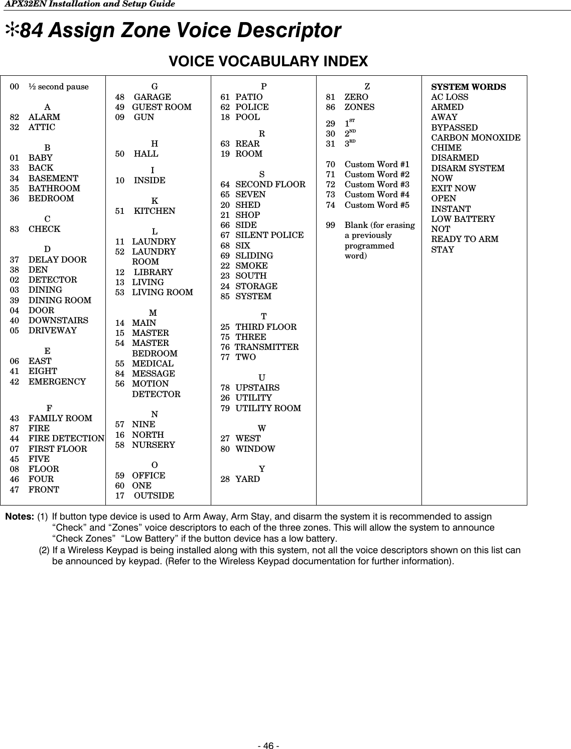
![APX32EN Installation and Setup Guide - 45 - ✻84 Assign Zone Voice Descriptors Use this mode to assign voice descriptors for each zone. These are the descriptors that are announced when the system announces any event involving a zone number. Each descriptor can consist of up to 3 words. Press ✻84 while in Programming mode. The prompts for ✻84 are as follows: 84 Voice Descriptors ----------------- Main Menu prompt A 02 Zone Number----------------------- for entering the zone number to be programmed b Descriptor 1------------------------- for assigning the first word of this zone’s descriptor C Descriptor 2------------------------- for assigning the second word of this zone’s descriptor d Descriptor 3------------------------- for assigning the third word of this zone’s descriptor The following explains these prompts in detail. The left two columns identify the prompts and list the available entries. The right-most column provides a further explanation of the entries. Note: Entering a number other than the one specified will give unpredictable results. 84 Assign zone voice descriptors 0 = exit mode 1 = enter mode Pressing 1 advances to the next prompt below. Pressing 0 exits mode, upon which this prompt blinks, indicating the mode is inactive. A zz Zone number [✻] = continue to next prompt (any existing descriptors will be announced, then descriptor 1 will be repeated) 00 = exit voice descriptor mode Enter the 2-digit zone number for which this descriptor is being assigned, then press [✻]. The Voice Descriptor for the selected zone will be announced, if it is programmed. b vv Descriptor 1 Enter [#] + 2-digit vocabulary index number of first descriptor word for this zone. 6 = accept word and advance to descriptor 2 (descriptor 2 will be announced) 8 = accept word and advance to prompt (A) for next zone. Press any other key to repeat the selected word. Enter the first word of the descriptor for the selected zone. Use the [6] or [8] key to advance as described. To change the entered index number before pressing [6] or [8], simply press [#] + desired 2-digit vocabulary index number. If descriptor 1 is not desired, enter [#] + 99 (blank), then press [8] to return to zone number prompt. C vv Descriptor 2 Enter [#] + 2-digit vocabulary index number of second descriptor word for this zone. 6 = accept word and advance to descriptor 3 (descriptor 3 will be announced) 8 = accept word and advance to prompt (A) for next zone. Press any other key to repeat the selected word. Enter the second word of the descriptor for the selected zone. Use the [6] or [8] key to advance as described. To change the entered index number before pressing [6] or [8], simply press [#] + desired 2-digit vocabulary index number. If descriptor 2 is not desired, enter [#] + 99 (blank), then press [8] to return to zone number prompt. d vv Descriptor 3 Enter [#] + 2-digit vocabulary index number of third descriptor word for this zone. 6 or 8 = accept word and advance to prompt (A) for next zone. Zone descriptor will be announced. Press any other key to repeat the selected word. Enter the last word of the descriptor for the selected zone. Use the [6] or [8] key to advance as described. To change the entered index number before pressing [6] or [8], simply press [#] + desired 2-digit vocabulary index number. If descriptor 3 is not desired, enter [#] + 99 (blank), then press [8] to return to zone number prompt.](https://usermanual.wiki/Ademco/8DLLYNXREN-6/User-Guide-883200-Page-45.png)
![APX32EN Installation and Setup Guide - 47 - ✻85 Record Custom Voice Descriptors Use this mode to record up to 5 custom voice descriptors. Press ✻85 while in Programming mode. Note: Entering a number other than one specified will give unpredictable results. 85 Assign custom voice descriptors 0 = exit mode 1 = enter mode Entering “1” advances to the next prompt below. Entering “0” exits mode, upon which this prompt blinks, indicating the mode is inactive. A 7d Custom descriptor number Enter 7 + d + [✻] Where d = 0-4, each representing custom word 70, 71, 72, 73, or 74, respectively. Any existing word will be announced. Press [#] to start recorder. Begin speaking immediately after the third beep. Speak the desired word clearly near the microphone. Recording stops after 1.5 seconds. 6 = accept word and ready to record next descriptor prompt (A….7d) [#] = re-record descriptor 00 = exit Record mode after pressing 6 to accept word Press any key to repeat the recorded word. Record up to 5 custom words.](https://usermanual.wiki/Ademco/8DLLYNXREN-6/User-Guide-883200-Page-47.png)
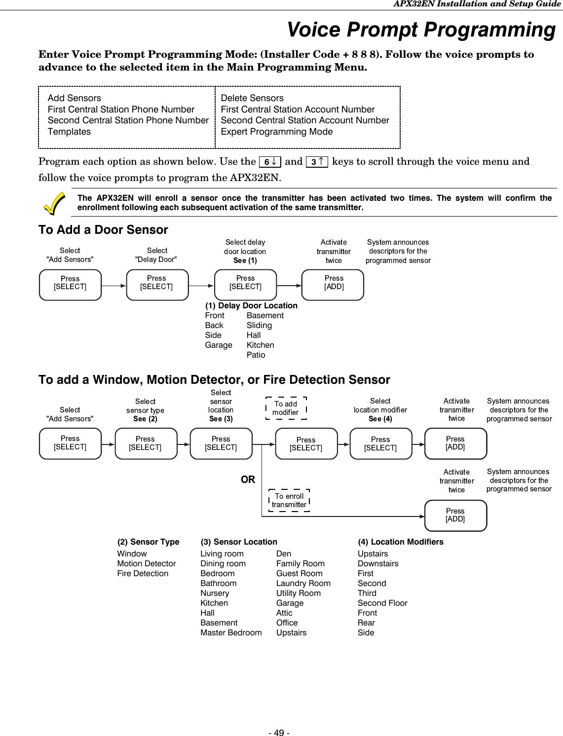
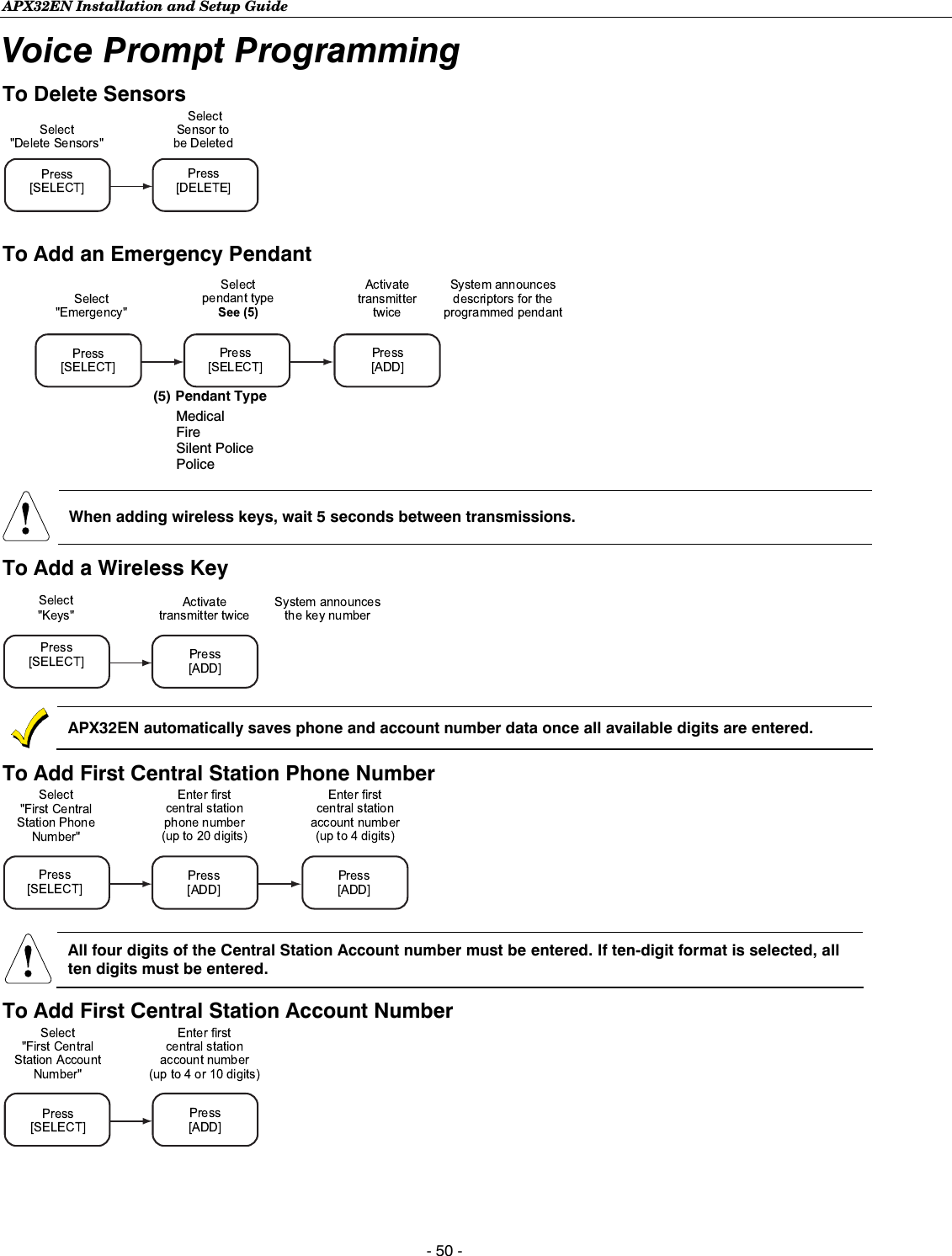
![APX32EN Installation and Setup Guide - 51 - Voice Prompt Programming All four digits of the Central Station Account number must be entered. If ten-digit format is selected, all ten digits must be entered. To Add Second Central Station Phone Number To Add Second Central Station Account Number Refer to the APX32EN Programming Default Tables to view the complete set of Template (default table) selections. To Program a Template (Default Table) (6) Template selections Template 1 Template 2 Template 3 Template 4 To Enter Expert Programming Mode Once you have entered the Expert Programming Mode, the [ESCAPE] key can be used to return to the Voice Prompt Programming mode.](https://usermanual.wiki/Ademco/8DLLYNXREN-6/User-Guide-883200-Page-51.png)
![APX32EN Installation and Setup Guide - 52 - Remote Programming/Control (Downloading) General Information The control panel can be remotely programmed from an IBM-compatible Personal Computer (PC) and ADEMCO’s Compass Downloader a HAYES Modem or via capable GSM or IP communications module. UUUULLLL Downloading may only be performed if a technician is at the site. Multiple security levels protect remote programming against compromise by attempts to defeat the system. 1. Security Code Handshake: An 8-digit download ID code must be matched between the Control and downloader. 2. Site-Initiated Remote Programming: The installer or subscriber initiates the call from the subscriber premises (by entering Installer Code + # + 1) while disarmed. All parameters can then be downloaded via the phone lines using a personal computer. 3. Station-Initiated Remote Programming: The operator calls the site from your office to initiate the download call. The Control hangs up and then calls back the PC via the preprogrammed telephone number. The unit can then be uploaded, downloaded, or controlled from your office. 4. Telco Handoff: The installer or subscriber performs a download session on the call initiated from the site or from local laptop computer (by entering Installer or Master Code + # + 1 at the control panel). 5. Data Encryption: Data passed between the PC and the Control is encrypted for security so that it is very difficult for a foreign device tapped into the phone line to take over communication and substitute system-compromising information. Equipment required to download to a system at the premises • An IBM PC compatible computer and appropriate interconnecting cables. • Either a HAYES brand SMARTMODEM 1200 (Level 1.2 or higher external or Level 1.1 or higher [with 4 position DIP switch] internal style), a HAYES brand Optima 336 external, a HAYES brand Optima 24 Plus FAX96, or an Ademco CIA Modem or via a capable GSM or IP communications device. • Compass Downloader for Windows (at revision level supporting APX32EN). Initial Download: Enter Installer Code + # + 5. This sets field ✻95 to 4 rings, and system to “no call-back” option. The download computer can then call the subscriber, make connection, and download all programming data. Flexible Callback: If enabled in field ✻93, the download operator can temporarily change the last 1, 2, or 3 digits (depending on selection) of the call back number. This allows the control to call back a computer other than the one programmed, which may be helpful at times of high computer traffic. See field ✻93 for a full description. Remote Programming Information If using Remote Programming, the APX32EN must be connected to the telephone line or to the Internet, as applicable. The downloading system can perform many functions when in communication with the Control. Besides uploading and downloading, the status of the system can be observed and various commands can be initiated, as follows: • Arm the system in the away mode; disarm the system. • Bypass a zone. • Force the system to accept a new program download. • Shut down communication functions (for nonpayment of monitoring fees in an owned system). • Shut down all security system functions (for nonpayment for a leased system). • Inhibit local keypad programming (prevents account takeover).](https://usermanual.wiki/Ademco/8DLLYNXREN-6/User-Guide-883200-Page-52.png)
![APX32EN Installation and Setup Guide - 54 - System Operation Security Codes Installer Code The installer programs the 4-digit Installer Code initially as part of the programming procedure. The factory default Installer Code is 4-1-1-2, but may be changed in field ✻20. The Installer Code is the only code that can enter Programming mode and also, in normal operation mode, is used to enter the Master Code, which allows access to the normal functions of the system. Master Code In normal operation mode, the Installer Code is used to enter the 4-digit Master Security Code. To enter/change the Master code by installer, using the keypad enter: Installer Code + [CODE key] + [02] + desired 4-digit Master Code To change the Master code by master, using the keypad enter: Current Master Code + [CODE key] + [02] + new Master Code + new Master Code again Secondary User Codes In normal operation mode, the Master Security Code can be used to assign up to 6 secondary 4-digit security codes, including a Babysitter Code and a Duress Code. The Master Code can also be used to remove secondary codes from the system (individually). To assign (or change) a secondary security code, using the keypad enter: Master Code + [CODE key] + User # (03–08) + desired Secondary Code The system will emit a single beep when each secondary code has been successfully entered. To delete a secondary security code, using the keypad enter: Master Code + [CODE key] + User # (03–08) Security Code Notes • The Master and Secondary security codes permit access to the system for arming, disarming, etc. • The Installer Code can disarm the system only if it was used to arm it. In addition, the Installer Code cannot disarm the system if it was armed by pressing and holding a Quick-Arm button. • The Babysitter Code (User Code No. 7) can disarm the system only if it was used to arm it. In addition, the Babysitter Code cannot disarm the system if it was armed by pressing and holding a Quick-Arm button. • Duress code (User Code No. 8) sends a special code to the monitoring station when used to perform any system operation.. Instruct users to be careful not to use this code for normal usage. If the duress code is programmed, you must enter a report code for Zone 92 (duress). • If a secondary code is inadvertently repeated for different users, the lower user number will take priority. • Opening/closing reports are sent for the Installer Code as No. 01, with the appropriate subscriber number. Master Code and set of secondary user codes are sent as Nos. 02 and 03–08, respectively, in Contact ID® format (with the appropriate user number); in 4+2, it is 1–8. Quick arming (and open/close executed by downloader) is reported as user 00. Panic Keys There are three panic key pairs that, if programmed, can be used to manually initiate alarms and send a report to the central station. Each can be individually programmed for 24-hour silent, audible, personal or fire emergency responses. The panic function is activated when both keys of the appropriate key pair are pressed at the same time. The panic functions are identified by the system as follows: Keys Displayed as Zone [1] & [✻] 95 [✻] & [#] 99 [3] & [#] 96 Important: For the silent panic functions to be of practical value, the system must be connected to a central station.](https://usermanual.wiki/Ademco/8DLLYNXREN-6/User-Guide-883200-Page-54.png)
![APX32EN Installation and Setup Guide - 55 - System Operation Keypad Functions The keypad allows the user to arm and disarm the system, and perform other system functions, such as bypassing zones. Zone and system conditions (alarm, trouble, bypass) are displayed in the display window. When an alarm occurs, keypad sounding and external sounding will occur, and the zone(s) in alarm will be displayed on the keypad. Pressing any key will silence the keypad sounder for 10 seconds (only once). Disarming the system will silence both keypad and external sounders. When the system is disarmed, any zones that were in an alarm condition during the armed period will be displayed (memory of alarm). To clear this display, simply repeat the disarm sequence (enter the security code and press the OFF key). The keypad also features chime annunciation, and 3 panic key pairs for silent, audible, fire or personal emergency alarms. These keys can notify the central station of an alarm condition, if that service is connected. A summary of system functions is provided below for more detailed information refer to the User’s Manual. Security Functions (Empty boxes represent the user’s security code) Checking system status: ............................. STATUS (high level messages); press STATUS again for secondary messages To arm in STAY mode: .............................. + STAY (or installer code + [3]) To restart exit delay: ............................... STAY (applies only if system is armed in Stay mode) To arm in AWAY mode:............................... + AWAY (or installer code + [2]) To arm with NO DELAY: ............................ + AWAY or STAY + NO DELAY OR ................................................................................................... + AWAY INSTANT OR STAY INSTANT To arm if Quick Arm is programmed:......... AWAY or STAY (hold down for at least 2 seconds) To disarm the system and silence alarms:. + OFF Note: During Entry Delay or when an Alarm Condition exists the system can be disarmed by entering the User Code. Entering the OFF key is not required. To bypass a zone(s): .................................... + BYPASS + 2-digit zone number(s) To turn Chime mode on or off: ................... FUNCTION + CHIME Message Center To record a message:.......................................... FUNCTION + RECORD To stop recording before end of 90 seconds:OFF To play back a message:.................................... FUNCTION + PLAY To skip a message: ............................................. [✻] To delete all messages:...................................... FUNCTION + DELETE (during message replay) Volume Control To adjust message playback/system announcement volume: FUNCTION + VOLUME + [3] or [6] To mute system announcements: ............... FUNCTION +VOLUME + OFF To restore/unmute announcement & volume: FUNCTION + VOLUME + [3] or [6] Other Functions To set the time and date: ............................ + FUNCTION + [63] To set the scheduling: ................................. + FUNCTION + [64] To add a user code: ..................................... *+ CODE + user number + user’s code (*master code) To delete a user code (except Master Code): *+ CODE + user number (* master code) To turn Test mode on: ................................. + TEST To turn Test mode off: ................................. + OFF](https://usermanual.wiki/Ademco/8DLLYNXREN-6/User-Guide-883200-Page-55.png)
![APX32EN Installation and Setup Guide - 56 - System Operation To use the defined AUX function: .................. Press and hold AUX key 2 secs (4 beeps) + To define AUX function: .............................. + FUNCTION + AUX + action separated by + AUX terminated by + AUX + AUX To send message to pager: .......................... Press and hold AUX key 2 seconds (4 beeps) To program Follow Me Reminder telephone number: + FUNCTION + [65] Speaker Phone Operation To place a call or answer a call using the speaker phone: [#] + AUX To flash (switch between two calls using call waiting): AUX To hang up and exit speaker phone mode:. OFF To enable/disable (toggle) ringer: ................ [#] + VOLUME + AUX To return the keypad to telephone mode after disarming the system: [#] + AUX Remote Phone Control Feature The remote phone control feature, which must be enabled in field ✻91, allows the user to access the security system from any off-site touch-tone telephone. The control will pick up the incoming call, based on the ring count specified in field ✻95, and will announce “SYSTEM ENTER CODE” every three (3) seconds for the next eight (8) seconds. During this period the panel will wait for a valid User Code to be entered. If a valid User Code is not entered or the eight (8) second period expires a modem tone will be generated for remote programming (Compass Downloading). If a valid User Code has been entered, the control will announce the current system status and/or beeping sounds. Keypad Functions Remote Phone Control Feature To remotely disarm system:............................. + [1] To remotely arm in AWAY mode: .................. + [2] To remotely arm in STAY mode:........................ + [3] To remotely arm in AWAY or STAY with no delay: + [2] or [3] + [0] To remotely Bypass zones: ............................... + [6] + zone no. To remotely activate Forced Bypass: ............ + [6] + [#] To remotely check system status:................... [✻] To end remote phone control session: ........... Hang Up or enter + [9] Quick Arm Note The installer code and babysitter code cannot disarm the system if armed by Quick Arm method.NOTE The ARMED and READY LEDs blink alternately when the Speaker Phone is active.](https://usermanual.wiki/Ademco/8DLLYNXREN-6/User-Guide-883200-Page-56.png)
![APX32EN Installation and Setup Guide - 57 - System Operation UUUULLLL Audio alarm verification has not been evaluated by UL. Audio Alarm Verification (Two-Way Voice Feature) This feature allows the central station operator to listen, talk to or conduct a two-way conversation with an individual(s) at the premises. It also assists the operator in gathering information about the nature and location of the alarm that may be helpful in responding to police and fire departments. All APX32EN control panels are capable of supporting the Two-Way Voice feature. The APX32EN does not make system announcements when the Two-Way voice feature is active. Activation Fire and CO alarms will not trigger an AAV session. A new Fire or CO alarm will end an AAV session that is in progress. The APX32EN sends the “alarm message” followed by a “Listen-in-to-Follow message” (Contact ID® code 606) to the Central Station. The Listen-in-to-Follow message causes the Central Station’s digital receiver to temporarily hold the phone line for approximately 1-minute. When the APX32EN receives the “kissoff” from the central station, indicating that the alarm message has been received, the Two-Way Voice (AAV) feature is activated in the (default) “Listen Mode” and sirens and keypad sounds are discontinued. The APX32EN transmits a beep acknowledgment to the Central Station, once per second. The beep alternates between two tones and indicates that the APX32EN is waiting for a session command from the Central Station operator. Once a command is issued the beep acknowledgement is discontinued, however, if a command is not issued within two minutes the system will “time out” and the call will be terminated. Operator Commands The Central Station operator begins the session, which last 5 minutes, by entering one of the valid AAV commands shown in the table below. The session may be extended 5 minutes, without changing the operating mode, by pressing the [7] key on the touch-tone phone. Selecting another operating mode also resets the session an additional 5 minutes. During the last minute of the 5 minute, session, the APX32EN generates two beeps every 30 seconds to alert the Central Station operator that the session is about to time out. The Central Station operator may then extend the session by pressing the [7] key on the touch-tone phone. If the session is not extended the phone line is disconnected, and the session is ended. Sessions may be ended at any time by pressing the [9] key on the touch-tone phone. The AAV modes are described as follows: Note: When entering AAV commands make sure the Central Station receiver has been disconnected from the phone line, otherwise AAV commands may not go through. Key Function 1 Talk Mode: Pressing the [1] key on the touch tone phone, enables one-way voice communication from the central station to the violated premises, and allows the operator to talk communicate through the APX32EN speaker. In this mode the ARMED (red) and READY (green) LEDs blink alternately. 2 VOX (Voice) Mode: Pressing the [2] key on the touch-tone phone, enables two-way voice communications between the central station and the violated premises. In this mode the ARMED (red) and READY (green) LEDs blink alternately. 3 Listen Mode: Pressing the [3] key on the touch-tone phone, enables one-way audio from the violated premises to the central station. The Listen Mode is the start up default mode of the voice feature and allows the operator to listen through the APX32EN microphone. This mode does not affect the existing LED pattern. 7 Extends the session 5 minutes without changing its operating mode. 9 Ends the session and disconnects the phone line.](https://usermanual.wiki/Ademco/8DLLYNXREN-6/User-Guide-883200-Page-57.png)
![APX32EN Installation and Setup Guide - 58 - System Operation “Follow Me” Reminder Feature This feature allows the user to schedule a time driven message. When activated the system will dial a phone number, that the installer programs in Field ✻46, and deliver a voice message (custom words 72, 73, and 74). The APX32EN will immediately begin transmitting the voice message and will repeat the message for 45 seconds. Pressing any touch-tone key on the answering phone will acknowledge the message ending the session and preventing the system from redialing the programmed number. Delivery of a reminder message on the local APX32EN keypad will continue. If the message has timed out the system will redial the programmed number a maximum of seven additional times or until it is acknowledged. Pressing any key on the APX32EN keypad will terminate (acknowledge) both the follow me reminder and the local reminder announcements. Notes: (1) This feature is only supported if programmed in field ✻49. (2) The follow me reminder will be terminated if any other event requires the system to dial out, or if an audible alarm has occurred, however, delivery of the local schedule reminder message will continue. “Follow Me” System Announcement Feature This feature allows the APX32EN to deliver a voice system message to the secondary phone number programmed by the installer. The APX32EN will first transmit reports to the Central Station and after receiving its kiss-off the system will dial the secondary phone number and begin transmitting the voice message. This message is a repeatable system status announcement. Like the Follow Me reminder, pressing any key on the answering telephone or the local APX32EN keypad will terminate (acknowledge) the message. The system will dial the secondary phone number a maximum of eight times. The Follow Me alarm functions may be triggered by a variety of events depending upon the selections made during programming in field ✻49. Note: The follow me system announcement will be terminated if any other event requires the system to dial out or if an audible alarm has occurred. Powerline Carrier Devices (e.g. X10 devices) If Powerline Carrier Devices are used, two keypad entries available to the user are included. They can manually activate or deactivate the device(s) for starting or stopping some action, such as turning lights on or off, etc. These keypad entries are: Security Code* + [#] + [4] + Device # activates (starts) that device. Security Code* + [#] + [7] + Device # de-activates (stops) that device. *Code is required for devices 7 and 8. Code is not required for devices 1-6. Exit Error Alarm Displays The system will display the following if programmed in Field *59. Display Meaning CA will appear along with a zone indication if an exit or interior zone contained a fault during closing at the time the exit delay ended (e.g., exit door left open), but the system was disarmed during the entry delay time. The alarm sounder and keypad sound continuously, but stop when the system is disarmed. No message will be transmitted to the central station. EA will appear along with a zone indication if an exit or interior zone contained a fault during closing at the time the exit delay ended, but the system was NOT disarmed during the entry delay time. The alarm sounder and keypad sound continuously until the system is disarmed (or timeout occurs). An Exit Alarm message is sent to the central station. OR if an alarm from an exit or interior zone occurs within two minutes after the end of an exit delay Entering a second OFF sequence (Code + OFF ) will clear the display.](https://usermanual.wiki/Ademco/8DLLYNXREN-6/User-Guide-883200-Page-58.png)
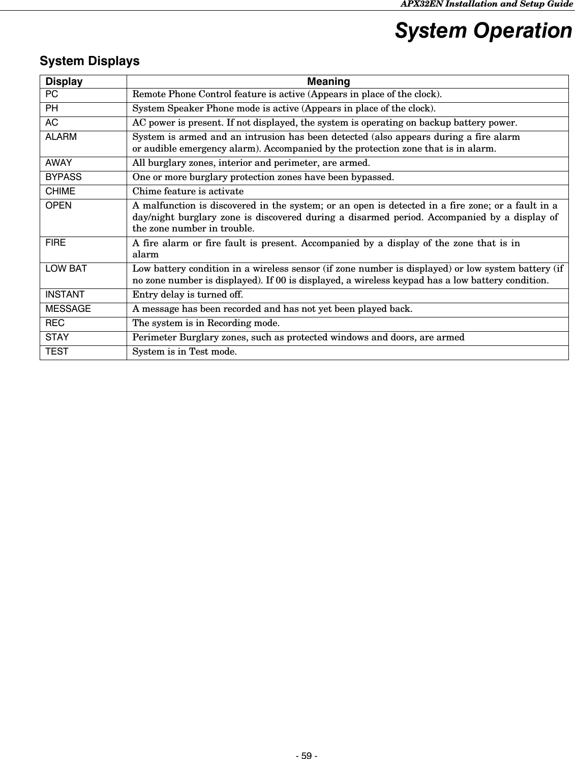
![APX32EN Installation and Setup Guide - 60 - Testing the System Test ModeAfter installation is completed, the security system should be carefully tested, as follows. 1. With the system in the disarmed state, check that all zones are intact. If the READY LED is not lit, press the [ ✻] key to display the faulted zone(s). Restore faulted zone(s), if necessary, so that the READY LED lights. Fault and restore every sensor individually to assure that it is being monitored by the system. 2. Enter the security code and press the TEST key. The outside sounder will sound for 1 second and all the LED segments on the keypad display light for 3 seconds. APX32EN announces the zone’s voice descriptor (if programmed) followed by 3 beeps, each time a contact is faulted. A test report should be transmitted (if programmed) to the central station immediately. If the backup battery is discharged or missing, the sounder may not turn on and a LOW BATTERY report will be transmitted with a TEST report. The keypad will beep once every 45 seconds as a reminder that the system is in the Test mode. 3. To turn off the Test mode enter security code and press the OFF key. Notes: (1) Triggering a zone set to Arm AWAY, Arm STAY, or Disarm will take the system out of Test and cause that action. (2) BR type transmitters do not display during Test mode (keypad beeps only) (3) Macros cannot be run from the Test mode. (4) Test mode automatically ends after 4 hours. During the final 5 minutes (after 3 hours 55 minutes of Test mode), “TEST” flashes on the keypad indicating that the end of Test mode is nearing. (5) Upon termination of a test mode all faulted 24-hour zones are treated as a trouble zones. (6) Fire verification is disabled when the system is in Test mode. Armed System TestAlarm messages will be sent to the central station during the following tests 1 and 2. Notify them in advance that tests will be in progress. 1. Arm the system and fault one or more zones. After 15 seconds (if optional burglary abort is selected), silence alarm sounder(s) by entering the code and pressing OFF. Check entry/exit delay zones. 2. Check the keypad-initiated alarms that are in the system by pressing the Panic key pairs. If the system has been programmed for audible emergency, the keypad will emit a steady alarm sound, and “ALARM” and zone number will be displayed. Silence the alarm by entering the security code. If the system has been programmed for silent emergency, there will be no audible alarms or displays, but a report will be sent to the central station. 3. If Powerline Carrier Devices have been installed, test their programmed action. 4. Notify the central station when all tests are finished, and verify results with them. 5. To test the wireless part of the system and the RF receiver, perform the two additional tests described in the Installing Wireless Zones section: Sniffer mode and Go/No Go Test. Note: System Test mode (installer/master code + test) and Go/No Go Test (installer code + # + 8) will be automatically terminated after 3-1/2 to 4 hours if the installer or user does not manually terminate it. This ensures that fire and panic zones will not remain disabled. However, Sniffer mode (installer code + # + 3) does not automatically expire. You must manually exit (Installer/User Code + OFF) Sniffer mode to return to normal operation. TO THE INSTALLER Regular maintenance and inspection (at least annually) by the installer and frequent testing by the user are vital to continuous satisfactory operation of any alarm system. The installer should assume the responsibility of developing and offering a regular maintenance program to the user as well as acquainting the user with the proper operation and limitations of the alarm system and its component parts. Recommendations must be included for a specific program of frequent testing (at least weekly) to ensure the system’s proper operation at all times.](https://usermanual.wiki/Ademco/8DLLYNXREN-6/User-Guide-883200-Page-60.png)
![APX32EN Installation and Setup Guide - 61 - System Communication This section provides an explanation of formats this system accommodates for reporting alarms and other system conditions to the central station. The process of a successful transmission consists of both the method of communication between the control panel and the central station receiver, and the actual way the information is sent and displayed at the central station. Communication Overview When the panel calls the central station receiver, it waits to hear a “handshake” frequency from the receiver to confirm that the receiver is on-line and ready to receive its message. Once the panel hears the handshake it is programmed to listen for, it sends its message. The panel then waits for a “kissoff” frequency from the receiver acknowledging that the message was received and understood. 3 If the handshake frequency is not given or is not understood by the panel, the panel will not send its message. Once the handshake frequency is received and understood by the panel, the panel will send its message. If there is an error in the transmission (the receiver does not receive a “valid” message), the kissoff frequency will not be given by the central station receiver. The panel will make eight attempts to the primary telephone number and eight attempts to the secondary telephone number (if programmed) to get a valid message through. If the panel is not successful after its numerous attempts, the keypad will display “FC.” If the secondary number is a pager, “FC” displays after the first 8 attempts to the primary number. The following chart defines the three sets of (handshake/kissoff) frequencies that the panel supports, and the different formats that can be sent for each. FORMAT HANDSHAKE TRANSMITS DATA KISSOFF TRANSMIT TIME Low Speed 1400Hz 1900Hz (10PPS) 1400Hz Under 15 seconds 3+1 (Standard report) 4+1 4+2 Sescoa/Radionics 2300Hz 1900Hz (20PPS) 2300Hz Under 10 seconds 3+1 (Standard report) 4+1 4+2 Express 1400–2300Hz DTMF (10 cps) 1400Hz Under 3 seconds 4+2 Contact ID® 1400–2300Hz DTMF (10 cps) 1400Hz Under 3 seconds Report Code Formats 3+1 and 4+1 Standard Formats Comprise a 3- (or 4-) digit subscriber number and a single digit report code (e.g. alarm, trouble, restore, open, close, etc). 3+1 and 4+1 Expanded Formats Comprise a 3- (or 4-) digit subscriber number, and a 2-digit report code. The first digit is displayed on the first line, followed by a second line where the first digit is repeated 3 (or 4) times and followed by the second digit. This is the “expanded” digit. 4+2 Format Comprises a 4-digit subscriber number and 2-digit report code. ADEMCO Contact ID® Comprises a 4-digit subscriber number, 1-digit event qualifier Reporting Format (“new” or “restore”), 3-digit event code, and 3-digit zone number, user number, or system status number (see the following page). The following table shows the message formats for 3+1, 4+1 and 4+2 reports, where: SSS or SSSS = Subscriber ID C = Close Code (1st Digit) A = Alarm Code (1st digit) U = User Number (in hex) Z = Typically Zone Number* (2nd digit) G g = Test Code (1st & 2nd digits) T t = Trouble Code (1st & 2nd digits) R = Alarm Restore Code Bb = Bypass Code (1st & 2nd digits) R Tt = Trouble Restore Code (1st & 2nd digits) EAC = AC Loss Code (1st & 2nd digits) R Bb = Bypass Restore Code (1st & 2nd digits) LLB = Low Battery Code (1st & 2nd digits) R AAC = AC Restore Code (1st & 2nd digits) O = Open Code (1st Digit) RLLB = Battery Restore Code (1st & 2nd digits) *Zone numbers for: [*] & [#] = 99; [1] + [*] = 95; [3] + [#] = 96; Duress = 92](https://usermanual.wiki/Ademco/8DLLYNXREN-6/User-Guide-883200-Page-61.png)
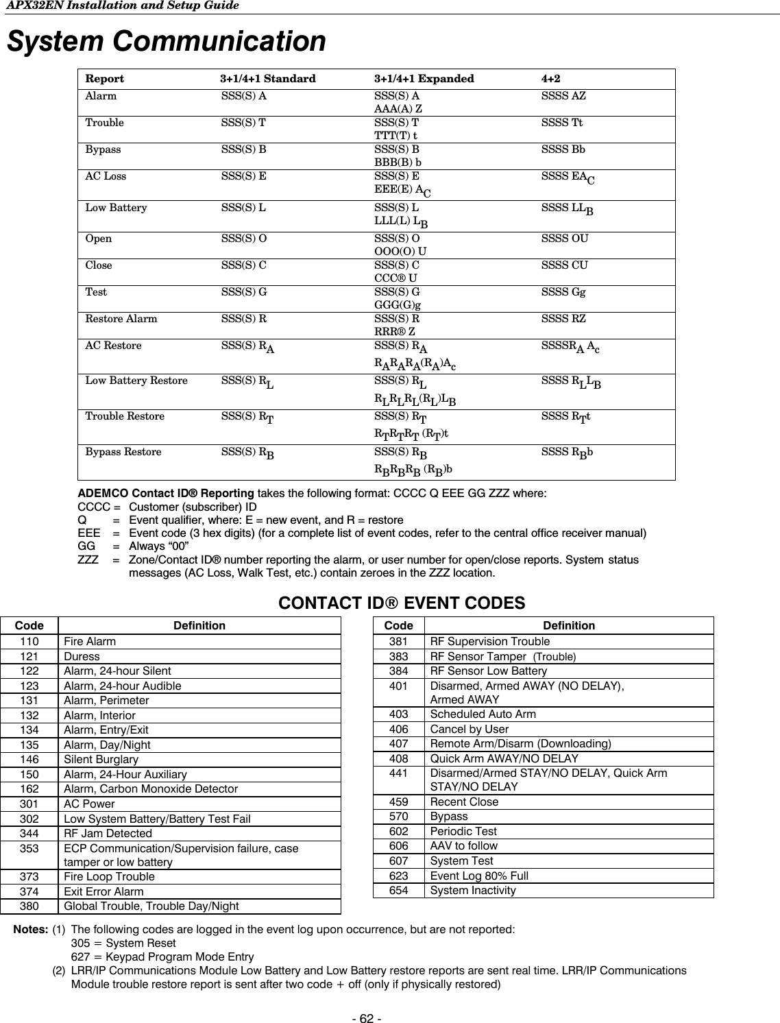
![APX32EN Installation and Setup Guide - 63 - Troubleshooting Guide Trouble Conditions The word “OPEN” on the keypad’s display, accompanied by a rapid “beeping” at the keypad, indicates that there is a trouble condition in the system. Pressing any key can silence the audible warning sound. Instruct users to call for service immediately upon seeing any of the following messages. System Trouble Displays Display Meaning OPEN and one or more zone numbers indicates that a problem exists with the displayed zone(s) and requires attention. After correcting the problem, the display can be cleared by entering the security code plus the OFF key twice. The fault condition may also be caused by some change in the environment that prevents the built-in receiver from receiving signals from a particular wireless sensor. OPEN 103 Indicates one of the following: • control panel lost communication with the communications module • communications module tamper detected (cover removed) • primary communications path failure • radio is not registered; account not activated • primary power loss • secondary communications path failure • battery charger failure • low battery LOW BAT with no zone number indicates that the system’s backup battery is weak. LOW BAT with a zone number and a once-per-45 seconds “beeping” at the keypad indicates that a low battery condition exists in the wireless sensor displayed (zone “00” indicates a wireless button/keypad). If the battery is not replaced within 30 days, a “OPEN” display may occur. bF Backup LRR/GSM/IP module communication failure (displayed on RF Keypad only) CA appears if an exit or interior zone contained a fault during closing at the time the Exit Delay ended (e.g., exit door left open), but the system was disarmed during the Entry Delay time. The alarm sounder and keypad sound continuously, but stop when the system is disarmed. No message will be transmitted to the central station. CC Modem Comm.: system is communicating with the central station for change of function or status verification. dI Busy-Standby displayed upon power-up. After approximately 1 minute* the green “READY” LED should light. If the “dI” remains displayed for more than 1 minute, the system is disabled. *To bypass the 1-minute delay, press [#] + [0]. Important: Do not try to bypass 1minute delay before “dI” is displayed! EA appears when Exit Delay ends if an exit or interior zone contained a fault during closing. The alarm sounder and keypad sound continuously until the system is disarmed (or timeout occurs). An “Exit Alarm” message is sent to the central station. Also results if an alarm from an exit or interior zone occurs within 2 minutes after the end of an Exit Delay. FC communication failure has occurred. This message clears only when the system is subsequently armed. 90 system has detected an RF jamming condition or excessive interference. No display Power Failure If there is no keypad display at all, and the LED indicators are not lit, operating power for the system has stopped and the system is inoperative. If the display is lit and the AC display is off, the system is operating on battery power only. During an AC power loss, the backlighting will turn off and the indicators will flicker slightly to minimize deep discharge of the battery.](https://usermanual.wiki/Ademco/8DLLYNXREN-6/User-Guide-883200-Page-63.png)