Ademco 8DLPLS8-USR3 GSM, WCDMA, LTE Module User Manual 800 08115
Honeywell International Inc. GSM, WCDMA, LTE Module 800 08115
Ademco >
Users Manual and Installation Revised
Communicators
Lyric-LTE Series
Installation Instructions
General Information
The Lyric-LTE series Communication Modules allow the Lyric Controller to communicate with the Central Station via the
cellular radio network. The Lyric-LTE series includes the following models:
• LYRICLTE-V (US, Verizon network)
• LYRICLTE-A (US, AT&T network)
• LYRICLTE-C (Canada)
FIRST TIME INSTALLATION NOTE: Before performing the first time installation of the communication module,
make sure power (both AC and battery) is removed from the controller and follow the Installing the Module (First
Time Installation) steps.
Installing the Module (First Time Installation)
1. Install the provided FCC/IC label on the control’s case back.
LYRICLTE-A & LYRICLTE-C: 800-22830
LYRICLTE-V: 800-22830-1
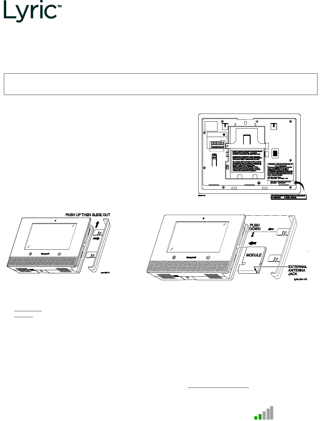
2. Remove bezel from right-hand side of control to expose the
communication module slot. To remove the bezel, push
upward then slide it out.
3. Insert the module into the slot. Push firmly to mate the edge
connector.
4. Replace the bezel.
5. After all other connections are made, power up the controller.
6. Program and register the module during the controller’s initial
association with its AlarmNet 360™ account. Refer to the
controller’s Programming Guide for details.
Typical FCC/IC Label Location
Removing the Bezel
Installing the communicator Module
7. Check the signal strength before permanently locating the Lyric Controller. See Checking Signal Strength section.
8. Test the communication paths.
Master User:
Security
–
Tools
–
[Master code]
–
Advanced
–
Comm. Test
Installer:
Security
–
Tools
–
[installer code]
–
Program – Comm. Diagnostcs - [
V
] – Test Communication
Press
Send Cellular Message
. Wait for “Ack Received” message.
Press
Send Ethernet Message
. Wait for “Ack Received” message.
“Ack Received” indicates successful communication.
If acknowledgement is not received, try one of the following:
a. Use an external antenna (see Using an External Antenna section).
b. Replace the radio with an alternate technology radio (ex., try 3G or CDMA).
c. Set the communication path to Wi-Fi-only.
Checking Signal Strength
When choosing a suitable mounting location, check the
communicator’s signal strength to ensure proper operation. For
most installations, using the module’s internal antenna, mounting
the Lyric controller as high as practical, and avoiding large metal
components provides adequate signal strength.
Use the Lyric Controller “Cellular Information” screen to display
signal strength (in number of bars):
Security
–
Tools
–
[installer code]
–
Program
–
Comm. Diagnostics
–
Cellular Information
Compare the signal strength number of bars displayed to the
Signal Strength Guide values at right to ensure adequate signal
strength.
If using AlarmNet 360, check that the display is minimum 2 bars.
If necessary, relocate the Controller to obtain better signal
strength (press
Cellular Information
again to refresh the reading).
Signal Strength Guide
Panel display signal strength:
range of 1-5bars;
should be minimum 2 bars
AlarmNet 360 Display
:
Must be minimum 2 bars lit.
If adequate signal strength cannot be achieved, an external antenna should be used. See Using an External Antenna
section on the other side.
PRELIMINARY
Ê800-21995yŠ
800-21995 2/17 Rev. A
2 Corporate Center Drive, Suite 100
P.O. Box 9040, Melville, NY 11747
Copyright © 2016 Honeywell International Inc.
www.honeywell.com/security
Communication Module Replacement
This procedure is intended only for replacement of existing communication modules previously installed and
registered in the Controller.
In the event the communication module needs to be replaced, the Lyric Controller must first be put in module
replacement mode (“Install Cellular Module”) to avoid causing a tamper alarm or damaging the module. Module
replacement mode deactivates tamper protection and removes power from the module connector for about 15
minutes.
1. Select the Install Cellular Module button.
Master User:
Security
–
Tools
–
[master code] –
Advanced
– Install
Cellular Module
Installer:
Security
–
Tools
–
[installer code]
–
Test – Install Cellular
Module
a. Select
Yes
at the prompt to continue.
b. A popup window displays steps for module replacement.
Keep this window open until replacement is completed
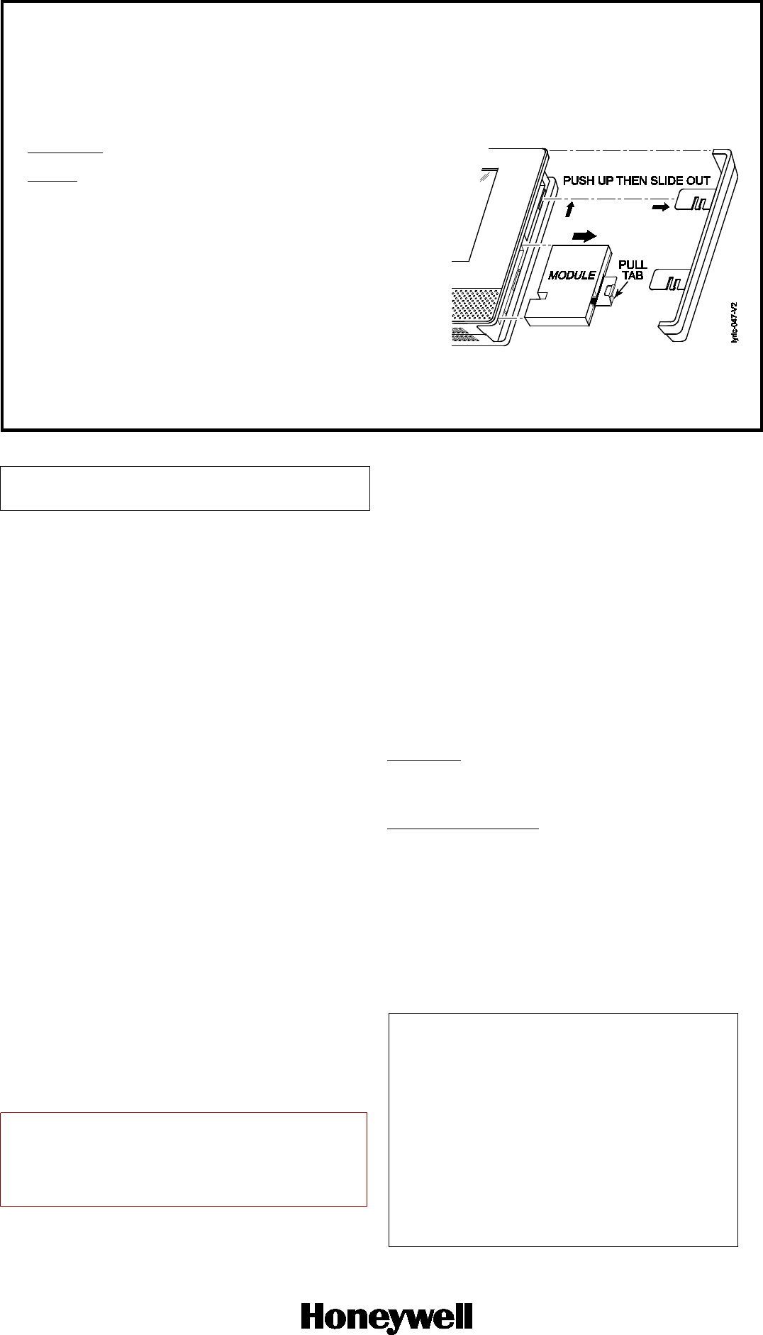
2. Remove the side bezel. See diagram at right.
3. Remove the communication module from its connection slot
by using the pull tab.
4. Insert the new module into the slot. Push firmly to mate the
edge connector.
5. Replace the bezel.
6. When installation is complete, press
OK
at the replacement
steps window. Confirmation of proper installation appears.
Press
OK
to exit.
7. Test the communication path. See step 8 in Installing the
Module section.
Replacing the Module
Using an External Antenna
If adequate signal strength cannot be achieved with the internal
antenna, an external antenna can be employed. A kit with an internal
adapter cable, clamp and bracket will be required and is available. A
connection diagram is provided in the kit which shows how to connect
a typical antenna to the device.
RF EXPOSURE WARNING
The antenna(s) used for this transmitter must be installed to provide a
separation distance of at least 7.8 in (20 cm) from all persons and must
not be co-located or operated in conjunction with any other transmitter
except in accordance with FCC multi-transmitter product procedures.
Mise en Garde
Exposition aux Fréquences Radio: L'antenne (s) utilisée pour cet
émetteur doit être installée à une distance de séparation d'au moins 7,8
pouces (20 cm) de toutes les personnes.
IMPORTANT NOTE ABOUT EXTERNAL ANTENNAS
If an external cellular radio antenna is used, the antenna may
be installed or replaced ONLY by a professional installer.
SUPPORT & WARRANTY
For the latest documentation and online support information,
please go to: https://mywebtech.honeywell.com/
For the latest warranty information, please go to:
www.honeywell.com/security/hsc/resources/wa.
For patent information, see www.honeywell.com/patents
Specifications
Dimensions: ....
2-5/8”W x 3-1/8”L x 1/2”D
Voltage Input
.. 5V (provided by the controller)
Current
LyricLTE-A / LyricLTE-C:
Idle ........................ 45mA, standby
Transmit max. .. 245mA RMS
LyricLTE-V:
Idle ........................ 45mA, standby
Transmit max. .. 245mA RMS
Environmental
Operating temperature: -20ºC to +55ºC,
(for compliance agency: 0ºC to +49ºC)
Storage temperature: -40º to +70ºC
Humidity: 0 to 95% relative humidity, non-condensing
(for compliance agency 0% to 85%)
Lyric LTE series Frequency Bands
LyricLTE-V:
PLS8-V
LTE: Triple band, 700 (Bd13) / AWS (Bd4) /
1900MHz (Bd2)
LyricLTE-A, LyricLTE-C:
GSM/GPRS/EDGE: Quad band,
850/900/1800/1900MHz
UMTS/HSPA+: Triple band, 850 (BdV) /
AWS (BdIV) / 1900MHz (BdII)
LTE: Quad band, 700 (Bd17) /
850 (Bd5) / AWS (Bd4) /
1900MHz (Bd2)
FEDERAL COMMUNICATIONS COMMISSION (FCC) &
INDUSTRY CANADA (IC) STATEMENTS
The user shall not make any changes or modifications to the
equipment unless authorized by the Installation Instructions or
User's Manual. Unauthorized changes or modifications could void
the user's authority to operate the equipment.
FCC / IC STATEMENT
This device complies with Part 15 of the FCC Rules, and RSS-210 of
IC. Operation is subject to the following two conditions: (1) This
device may not cause harmful interference (2) This device must
accept any interference received, including interference that may
cause undesired operation.
Cet appareil est conforme à la partie 15 des règles de la FCC & de
RSS-210 des Industries Canada. Son fonctionnement est soumis
aux conditions suivantes: (1) Cet appareil ne doit pas causer
d’interférences nuisibles. (2) Cet appareil doit accepter toute
interférence reçue y compris les interférences causant une
réception indésirable.
CABLE KIT: 100-05310
TO THE INSTALLER - Lyric-LTE Series
This device is to be used in mobile or fixed applications only. For
mobile and fixed operating configurations the antenna gain,
including cable loss, must not exceed 3.25 dBi (US) or 0.6 dBi (CA) in
the 850 MHz band, 5.5 dBi in the 1700 MHz band, and 2.5 dBi in the
1900 MHz band for satisfying RF exposure compliance. Under no
conditions may an antenna gain be used that would exceed the ERP
and EIRP power limits as specified in Parts 22H and 24E and 27.
PRELIMINARY
800-21995 3/17 Rev. B