Ademco 8DLTSSCBASE Security Base Control Unit User Manual Rev B
Honeywell International Inc. Security Base Control Unit Users Manual Rev B
UserManual.wiki
>
Ademco
>
8DLTSSCBASE User Manual
>
Users Manual Rev B
Contents
1.
Users Manual Rev B
2.
Quick Install Guide
Users Manual Rev B
Navigation menu
Upload a User Manual
Namespaces
Wiki Guide
HTML
PDF
Info
Views
User Manual
Discussion / Help
Navigation
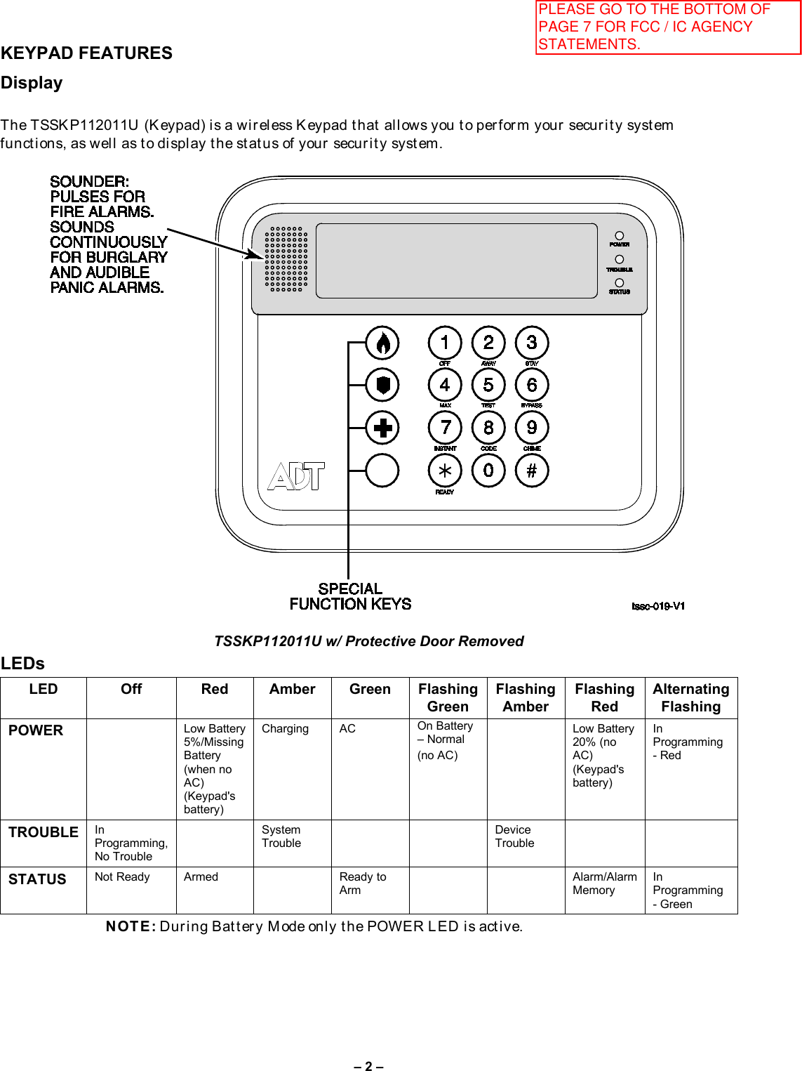
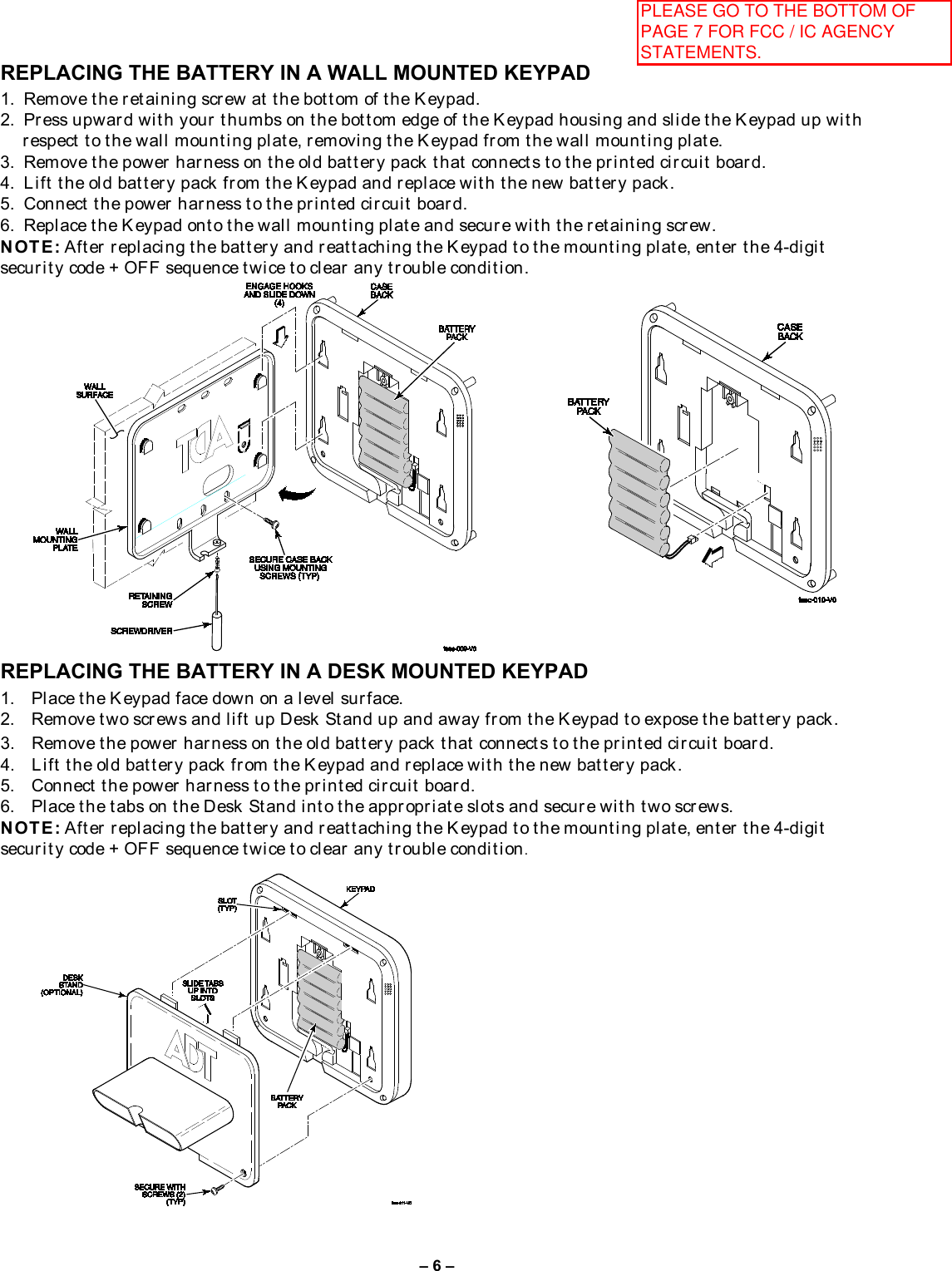
![– 3 –KEYS A ccess t h e Base con t r ol k eys by l i f t i n g up t h e door . T h e Key pad k eys ar e con t i n u ou sl y back l i t f or ease of use. Access t h e Keypad keys by op en i n g t h e sw i n g-dow n door . Th e Keypad k ey s ar e con t i n u ou sl y back l i t f or ease of u se. KEY DESCRI PTI ON OFF Di sar m s t h e bu r gl ar y por t i on of t h e sy st em, si l en ces al ar m s an d au di bl e t r ou bl e i ndi cat or s, an d cl ear s vi su al al ar m t r ou bl e af t er t h e pr obl em h as been cor r ect ed. AWAY Compl et el y ar m s bot h per i m et er an d i n t er i or bur gl ar y pr ot ect i on by sen si n g an i n t r u der 's m ov em en t s t h r ou gh pr ot ect ed i n t er i or ar eas as w el l as gu ar di n g pr ot ect ed door s, w i ndow s, et c. L at e ar r i v al s can en t er t h r ou gh an en t r y del ay zon e (en t r an ce door ) without causing an al ar m i f t h e sy st em i s di sar m ed bef or e t h e ent r y del ay t i m e expi r es. STAY A r ms t h e per i m et er bur gl ar y pr ot ect i on, guar di n g pr ot ect ed door s, w i n dow s an d ot her per i m et er pr ot ect i on poi n t s, and sou n ds an al ar m i f on e i s open ed. A l so al l ow s aut om at i c bypassing of cer t ai n ar eas w h i ch per mi t s m ovem en t w i t hi n you r h ou se wi t hou t cau si n g an alarm. Late arrivals can enter through an entry delay zone (en t r ance d oor ) without cau si n g an al ar m i f t he sy st em i s di sar m ed bef or e t h e en t r y del ay t i me ex pi r es. MAX Ar ms i n m an n er si m i l ar t o AWA Y m ode, bu t el i m i n at es t h e en t r y del ay per i od, t h u s pr ovi di n g m axi m u m pr ot ect i on . A n al ar m w i l l occu r i m m edi at el y u pon open i n g an y pr ot ect i on poi n t , i ncl u di n g en t r y del ay zon es (en t r an ce door s). T EST (K eypad on l y) - T est s t h e sy st em an d al ar m sou n der i f di sar m ed. BYPASS (K eypad on l y) - Rem ov es i n di v i du al pr ot ect i on zon es fr om bei n g m oni t or ed by t he sy st em. D i spl ays pr evi ousl y bypassed pr ot ect i on zon es. INSTANT A r ms i n m an n er si m i l ar t o ST A Y m ode, bu t t ur ns of f t he en t r y del ay per i od, of f er i n g gr eat er secu r i t y w h i l e i n si de and n ot expect i n g any l at e ar r i v al s. A n al ar m w i l l occur i mm edi at el y u pon open i n g an y per i m et er pr ot ect i on poi n t , i ncl u di n g en t r y del ay zon es. CODE (K eypad on l y) - A l l ow s t h e en t r y of addi t i on al u ser codes t h at can be gi v en t o ot h er u ser s of t h e sy st em. CHI ME (K ey pad on l y) - T u r n s on and of f t h e CH I M E m ode. Wh en on , an y en t r y t h r ou gh a pr ot ect ed del ay or per i m et er zon e w h i l e t h e sy st em i s di sar m ed w i l l cau se a t on e t o sou n d at the Keypad(s). READY (K ey pad on l y) - When depr essed pr i or t o ar mi n g t h e sy st em, t h e Keypad will display all open pr ot ect i on zon es w i t hi n t h e Keypad's h om e par t i t i on . T h i s k ey i s al so u sed t o di spl ay al l zon e descr i pt or s t h at h ave been pr ogr am m ed f or you r sy st em , by h ol di n g t h e k ey dow n f or at l east 5 secon ds. [#] (K eypad on l y ) - Per mi t s A RM I N G of t h e sy st em w i t hou t u se of a secu r i t y code ("Qu i ck Arm", i f pr ogr am m ed). N u m er i c k eys 0-9U sed t o en t er you r i n di vi du al secu r i t y access code(s). Speci al function k eysPanic alar m act i v at i on (Keypad on l y). The panic alar ms ar e activated by pr essing a Speci al F u n ct i on K ey (see bel ow ). Pani c k ey f u n ct i on al i t y and t h e t ype of pan i c al ar m s pr odu ced, i s det er m i n ed by t h e con t r ol pan el ’s capabi l i t y and pr ogr amm i n g. (Check with your installer for the availability and assignment of these panic keys.) SPECIAL FUNCTION KEYS (KEYPAD ONLY) The A, B, and C k eys l ocat ed t o t h e l ef t of t h e n u m er i c k eys can be pr ogrammed as Panic Alarm A ct i vat i on k ey s. (Check with your installer for the availability and assignment of these panic keys.) Key Function A B C PLEASE GO TO THE BOTTOM OF PAGE 7 FOR FCC / IC AGENCY STATEMENTS.](https://usermanual.wiki/Ademco/8DLTSSCBASE.Users-Manual-Rev-B/User-Guide-2240064-Page-3.png)
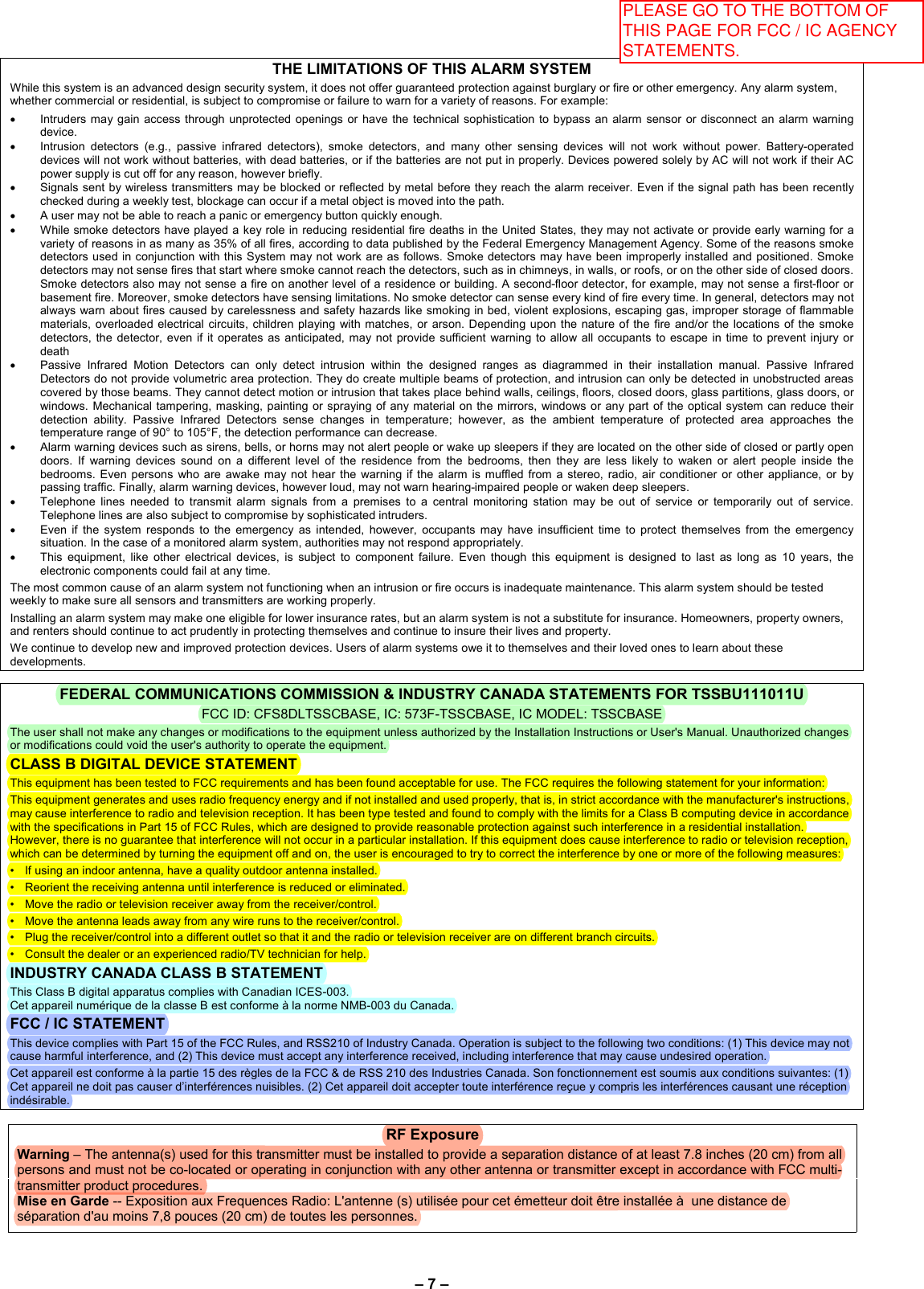
![– 4 –GENERAL OPERATION To mak e sur e t h e l at est syst em st at us i s di spl ayed, pr ess t he [*] k ey bef or e an d af t er en t er i ng each command. HOW TO GET SYSTEM STATUS The display continuously displays t h e pr esen t secur i t y sy st em st at us. Wh en t her e i s a chan ge i n sy st em st at u s (su ch as goi n g f r om an A RM ED ST A Y t o DI SA RM E D ), i t may t ak e up t o 20 secon ds f or t h e di spl ay t o aut omat i cal l y u pdat e t he st at us t o sh ow t h e st at u s ch an ge. H ow ever , y ou can pr ess t h e [*] k ey t o u pdat e t h e display immediately. ARMING THE SYSTEM To ar m t h e sy st em i n t h e A WA Y, ST A Y, I N ST A N T or M AX mode, en t er y ou r u ser code an d pr ess t h e n u m er i c k ey abov e t h e sel ect ed m ode. DISARMING THE SYSTEM To di sar m t h e sy st em en t er y ou r u ser code + OFF k ey [1]. BYPASSING ZONES To bypass an individual zon e, en t er you r user code + BYP ASS k ey [6] + f aul t ed zon e n u m ber of t h e zon e t o be bypassed. T o by pass m u l t i pl e zones, en t er t he com m an d st r i n g (u ser code + B YPA SS k ey [ 6]) then sequen t i al l y en t er t h e 3-di git zon e n u m ber s of t h e zon es t o be bypassed, u p t o f i ve zon es i n each com m an d. M u l t i pl e Zon e B ypass Exam pl e: u ser code + B YPA SS [6] + 003 004 005 007 009. I f you want t o bypass al l fault ed zones (F or ced B ypass), en t er y ou r user code + BYPASS k ey [6] + [#] + [0]. Th e F or ced B ypass f eat u r e must be en abl ed by y ou r i n st al l er : [ ] yes [ ] no USER CODES To Add a User IMPORTANT: T em por ar y u ser s should not be shown how to use any system function they do n ot need t o k n ow (e.g. bypassi ng pr ot ect i on zon es). E n t er M ast er code + CODE key [8] + 2-t w o di gi t user no. + 4-di gi t n ew u ser ’s code. U ser nu m ber s 02 t hr ough 96 ar e availabl e w i t h v ar i ous au t h or i t y l evel s. Note that User no. 01 i s u sed f or t h e M ast er code AUTHORITY LEVEL: E n t er M ast er code + CODE k ey [8] + 2-di gi t u ser n o. + [ #] + [1] + si ngl e-digit aut hor i t y l ev el . For aut h or i t y l ev el s, see def i ni t i on s bel ow . Level Title Explanation N/A Master Reserved for user 01; Can perform all system functions and assign codes. 0 Standard User Can only perform security functions. Cannot perform system functions reserved for the master user. 1 Arm Only Can only arm the system. Cannot disarm or do other functions 2 Guest Can arm the system and bypass zones, but cannot disarm the system unless the system was armed with this code. This code is typically assigned to someone (e.g., babysitter or cleaner) who has a need to arm/disarm the system only at certain times. 3 Duress Code Intended for use when you are forced to disarm or arm the system under threat. When used, the system will act normally, but can silently notify the Central Monitoring Station of your situation, if that service has been provided. To Change a User's Code Changing the Master code Enter Current Master code + CODE key [8] + 01 + 4-digit new code + 4-digit new code again. Changing a User code En t er M ast er code + CODE k ey [8] + 2-t w o di gi t u ser n o. + 4-di gi t new u ser ’s code. To Delete a User E n t er M ast er code + CODE k ey [8] + 2-digi t u ser code t o be del et ed + # + 0. A single con f i r m at i on t one w i l l be hear d and t h e code i s n o l on ger f u n ct i onal . PLEASE GO TO THE BOTTOM OF PAGE 7 FOR FCC / IC AGENCY STATEMENTS.](https://usermanual.wiki/Ademco/8DLTSSCBASE.Users-Manual-Rev-B/User-Guide-2240064-Page-4.png)
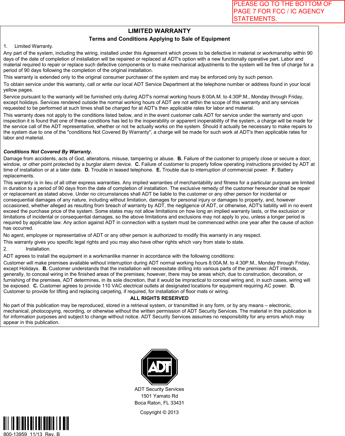
![– 5 –CHIME MODE You r syst em can be set t o al er t y ou t o t h e open i n g of a door or w i n dow w h i l e i t i s di sar m ed by u si ng CH I M E m ode. Wh en act i v at ed, t h r ee t on es sou n d at t h e K eypad w h en ev er a pr ot ect ed per i met er door or wi n dow i s open ed, and t h e “N ot Ready” m essage is displayed. Pressing the READY [*] key displays t h e open pr ot ect i on poi n t s. N ot e t h at Ch i me m ode can be act i v at ed on l y w h en t h e sy st em i s di sar m ed. 1. To turn Chime Mode on, ent er t h e secu r i t y code an d pr ess t he CHIME k ey [9].2. To turn Chime Mode off, en t er t h e secu r i t y code an d pr ess t h e CHI ME k ey again.KEYPAD TONES Wh en t h e K eypad i s gen er at i n g a per i odi c beep (on ce per m i n u t e), pr essi n g t h e [ * ] k ey pr ovi des m or e infor m at i on . Wh en t h e sy st em i s ar m ed an d t h er e i s a t r ou bl e con di t i on , t h e K ey pad di spl ay s “D ev i ce T r oubl e” . Pr essi n g t h e [ * ] k ey pr ovi des m or e i n f or m at i on. QUICK EXIT To st ar t Qu i ck Ex i t w h en en abl ed. St ay M ode – E n t er U ser code + ST A Y k ey. I nst an t M ode – E n t er U ser code + I N ST AN T k ey N ight -St ay M ode – With the system armed in Night-St ay M ode and t h e ex i t del ay ex pi r ed, en t er U ser code + ST A Y k ey + ST A Y k ey . HOST CHECK-IN I f H ost Ch eck -I n i n t er val i s set t o 200 secon ds, “D ow n l oad Com /U pl oad Com pl et ed” m essage i s di spl ayed at t h e K eypad ev er y 200 secon ds. TEST MODE U se T est m ode t o ch eck each pr ot ect i on poi n t f or pr oper oper at i on . Test i ng sh oul d be con du ct ed w eek l y t o en su r e pr oper oper at i on. 1. D i sar m t h e syst em and cl ose al l pr ot ect ed w i n dow s, door s, etc.2. En t er t he M ast er code + [ 5] (T E ST ), t h en pr ess 1.3. L i st en. Th e ex t er n al sou n der sh ou l d sou n d f or abou t 1 secon d t h en t ur n of f .4. Fau l t al l zon es i n t u r n an d l i st en f or t h r ee beeps f r om t he k eypad. I D of each f au l t ed point should appearon t h e k eypad di spl ay. T h e di spl ay cl ear s w h en t he zon e i s cl osed. N ot e t h at i f w i r el ess m ot i on det ect or sar e u sed, t h er e i s a 3-m i n u t e del ay bet ween act i vat i ons. T h i s con ser ves bat t er y l i fe.5. Test al l sm ok e an d CO det ect or s following the manufacturer's instructions and check the display.6. Wh en al l zon es h ave been ch eck ed an d ar e i n t act (cl osed), t h er e sh ou l d be n o zon e i den t i f i cat i onn u m ber s di spl ayed on t h e k eypad.7. Exit test m ode: secu r i t y code + [ 1] (OF F).NOT E S: •Th e k eypad sou n ds a si n gl e beep abou t ever y 60 seconds as a r emi n der t hat t h e syst em i s i n t he T estm ode. •A l ar m m essages ar e n ot sen t t o y ou r Cen t r al St at i on w h i l e Test m ode i s on .•I f a pr obl em i s exper i en ced w i t h an y pr ot ect i on poi n t (no con f i r mi n g sou n ds, n o di spl ay), cal l f or ser v i cei m m edi at el y .•I f t he t est m ode i s i nadv er t en t l y l ef t act i ve, i t aut om at i cal l y t u r n s of f af t er 30 m i nu t es. D u r i n g t h e f i n alf i v e m i n u t es, t h e k ey pad w i l l em i t a dou bl e beep ev er y 30 secon ds.PLEASE GO TO THE BOTTOM OF PAGE 7 FOR FCC / IC AGENCY STATEMENTS.](https://usermanual.wiki/Ademco/8DLTSSCBASE.Users-Manual-Rev-B/User-Guide-2240064-Page-5.png)