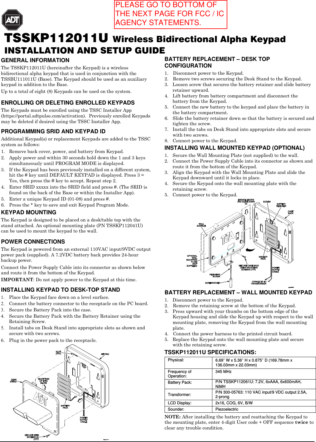
Ademco 8DLTSSCKP Wireless Keypad User Manual 800 13958V1 A TSSC Keypad ii

Honeywell International Inc. Wireless Keypad 800 13958V1 A TSSC Keypad ii

Users Manual

  TSSKP112011U Wireless Bidirectional Alpha Keypad INSTALLATION AND SETUP GUIDE GENERAL INFORMATION The TSSKP112011U (hereinafter the Keypad) is a wireless bidirectional alpha keypad that is used in conjunction with the TSSBU111011U (Base). The Keypad should be used as an auxiliary keypad in addition to the Base.  Up to a total of eight (8) Keypads can be used on the system.  ENROLLING OR DELETING ENROLLED KEYPADS  The Keypads must be enrolled using the TSSC Installer App (https://portal.adtpulse.com/activation).  Previously enrolled Keypads may be deleted if desired using the TSSC Installer App.    PROGRAMMING SRID AND KEYPAD ID Additional Keypad(s) or replacement Keypads are added to the TSSC system as follows: 1. Remove back cover, power, and battery from Keypad. 2. Apply power and within 30 seconds hold down the 1 and 3 keys simultaneously until PROGRAM MODE is displayed. 3. If the Keypad has been previously installed on a different system, hit the # key until DEFAULT KEYPAD is displayed. Press 3 = Yes, then press the # key to accept. Repeat step 2. 4. Enter SRID xxxxx into the SRID field and press #. (The SRID is found on the back of the Base or within the Installer App). 5. Enter a unique Keypad ID (01-08) and press #. 6. Press the * key to save and exit Keypad Program Mode. KEYPAD MOUNTING The Keypad is designed to be placed on a desk/table top with the stand attached. An optional mounting plate (PN TSSKP112041U) can be used to mount the keypad to the wall.     POWER CONNECTIONS  The Keypad is powered from an external 110VAC input/9VDC output power pack (supplied). A 7.2VDC battery back provides 24-hour backup power. Connect the Power Supply Cable into its connector as shown below and route it from the bottom of the Keypad.  IMPORTANT: Do not apply power to the Keypad at this time.  INSTALLING KEYPAD TO DESK-TOP STAND 1. Place the Keypad face down on a level surface. 2. Connect the battery connector to the receptacle on the PC board. 3. Secure the Battery Pack into the case. 4. Secure the Battery Pack with the Battery Retainer using the Retaining Screw. 5. Install tabs on Desk Stand into appropriate slots as shown and secure with two screws. 6. Plug in the power pack to the receptacle.   BATTERY REPLACEMENT – DESK TOP CONFIGURATION 1. Disconnect power to the Keypad. 2. Remove two screws securing the Desk Stand to the Keypad. 3. Loosen screw that secures the battery retainer and slide battery retainer upward. 4. Lift battery from battery compartment and disconnect the battery from the Keypad. 5. Connect the new battery to the keypad and place the battery in the battery compartment. 6. Slide the battery retainer down so that the battery is secured and tighten the screw. 7. Install the tabs on Desk Stand into appropriate slots and secure with two screws. 8. Connect power to the Keypad. INSTALLING WALL MOUNTED KEYPAD (OPTIONAL) 1. Secure the Wall Mounting Plate (not supplied) to the wall. 2. Connect the Power Supply Cable into its connector as shown and route it from the bottom of the Keypad. 3. Align the Keypad with the Wall Mounting Plate and slide the Keypad downward until it locks in place. 4. Secure the Keypad onto the wall mounting plate with the retaining screw. 5. Connect power to the Keypad.  BATTERY REPLACEMENT – WALL MOUNTED KEYPAD 1. Disconnect power to the Keypad. 2. Remove the retaining screw at the bottom of the Keypad. 3. Press upward with your thumbs on the bottom edge of the Keypad housing and slide the Keypad up with respect to the wall mounting plate, removing the Keypad from the wall mounting plate. 4. Connect the power harness to the printed circuit board. 5. Replace the Keypad onto the wall mounting plate and secure with the retaining screw. TSSKP112011U SPECIFICATIONS: Physical:    6.69” W x 5.36” H x 0.875” D (169.78mm x 136.03mm x 22.03mm) Frequency of Operation: 345 MHz Battery Pack:  P/N TSSKP112061U: 7.2V, 6xAAA, 6x600mAH, NiMH Transformer:  P/N 300-05763: 110 VAC input/9 VDC output 2.5A, 2-prong LCD Display:  2x16, COG, 6V, B/W Sounder:  Piezoelectric NOTE: After installing the battery and reattaching the Keypad to the mounting plate, enter 4-digit User code + OFF sequence twice to clear any trouble condition.  PLEASE GO TO BOTTOM OF THE NEXT PAGE FOR FCC / IC AGENCY STATEMENTS.
 REFER TO THE INSTALLATION INSTRUCTIONS FOR THE TSSBU111011U CONTROL WITH WHICH THIS DEVICE IS USED, FOR DETAILS ON LIMITATIONS OF THE ENTIRE ALARM SYSTEM.   FEDERAL COMMUNICATIONS COMMISSION STATEMENTS The user shall not make any changes or modifications to the equipment unless authorized by the Installation Instructions or User's Manual. Unauthorized changes or modifications could void the user's authority to operate the equipment.  CLASS B DIGITAL DEVICE STATEMENT This equipment has been tested to FCC requirements and has been found acceptable for use. The FCC requires the following statement for your information:  This equipment generates and uses radio frequency energy and if not installed and used properly, that is, in strict accordance with the manufacturer's instructions, may cause interference to radio and television reception. It has been type tested and found to comply with the limits for a Class B computing device in accordance with the specifications in Part 15 of FCC Rules, which are designed to provide reasonable protection against such interference in a residential installation. However, there is no guarantee that interference will not occur in a particular installation. If this equipment does cause interference to radio or television reception, which can be determined by turning the equipment off and on, the user is encouraged to try to correct the interference by one or more of the following measures:  •   If using an indoor antenna, have a quality outdoor antenna installed. •   Reorient the receiving antenna until interference is reduced or eliminated. •   Move the radio or television receiver away from the receiver/control. •   Move the antenna leads away from any wire runs to the receiver/control. •   Plug the receiver/control into a different outlet so that it and the radio or television receiver are on different branch circuits. •   Consult the dealer or an experienced radio/TV technician for help.  INDUSTRY CANADA CLASS B STATEMENT This Class B digital apparatus complies with Canadian ICES-003. Cet appareil numérique de la classe B est conforme à la norme NMB-003 du Canada.  FCC / IC STATEMENT This device complies with Part 15 of the FCC Rules, and RSS210 of Industry Canada. Operation is subject to the following two conditions: (1) This device may not cause harmful interference, and (2) This device must accept any interference received, including interference that may cause undesired operation.  Cet appareil est conforme à la partie 15 des règles de la FCC & de RSS 210 des Industries Canada. Son fonctionnement est soumis aux conditions suivantes: (1) Cet appareil ne doit pas causer d’interférences nuisibles. (2) Cet appareil doit accepter toute interférence reçue y compris les interférences causant une réception indésirable   For the latest warranty information, please go to: www.honeywell.com/security/hsc/resources/wa.          ADT Security Services 1501 Yamato Rd Boca Raton, FL 33431 Copyright © 2013    Ê800-13958V1ÅŠ 800-13958V1 11/13  Rev A PLEASE GO TO THE BOTTOM OF THIS PAGE FOR FCC / IC AGENCY STATEMENTS.

Navigation menu