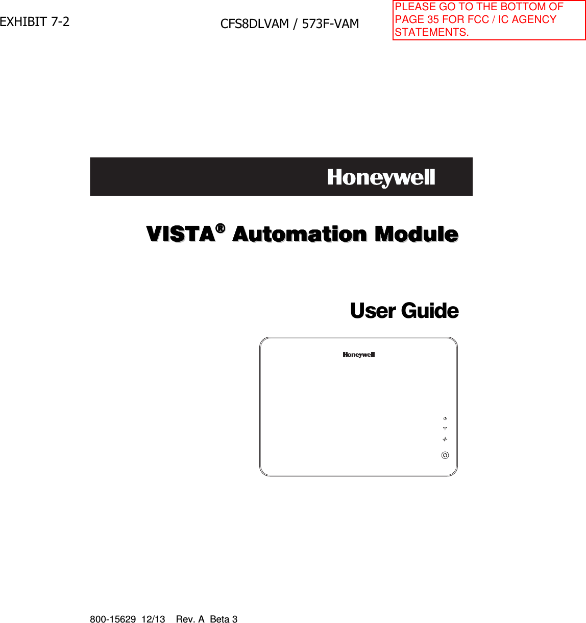
Ademco 8DLVAM Vista Automation Module User Manual 800 15629 A VAM ug beta4
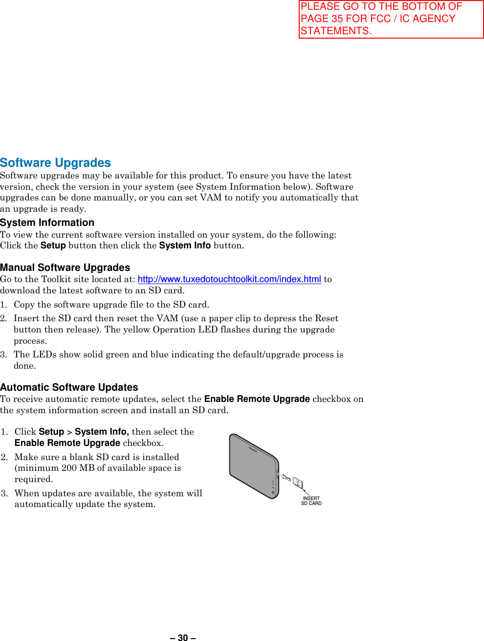
Honeywell International Inc. Vista Automation Module 800 15629 A VAM ug beta4
Ademco >
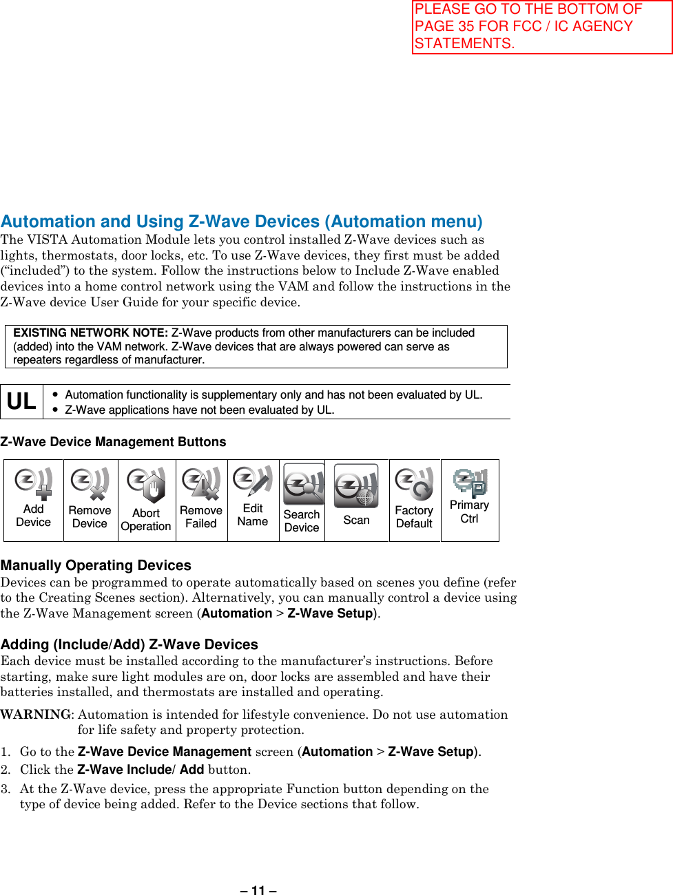
Contents
- 1. Users Guide Rev 042514
- 2. Quick Install Guide
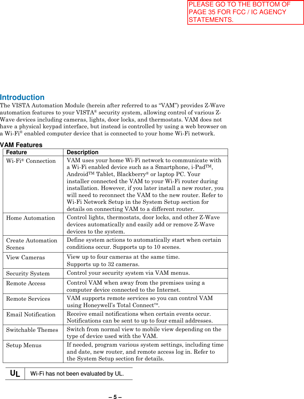
Users Guide Rev 042514