Ademco CTU-K05 CTU-K05 User Manual Tema1 0 TSTAxx IM 1 1 US
Honeywell International Inc CTU-K05 Tema1 0 TSTAxx IM 1 1 US
Ademco >
manual

TS TAxx
Integrated Interactive Terminals
Installation Manual

TABLE OF CONTENTS Page 3
TS TAxx
TABLE OF CONTENTS
FCC NOTICE...................................................................................................4
Canadian Compliance Statement...........................................................4
PRELIMINARY OPERATIONS............................................ 5
Mounting Instructions......................................................................................5
Electrical Connections ....................................................................................6
Cabling Arrangements ....................................................................................7
INSTALLATION ............................................................... 8
Attaching the Terminal Support Plate ............................................................8
Hooking Up the Terminal ................................................................................9
Connecting the Cables..................................................................................10
Jumpers.........................................................................................................13
Auxiliary Connections ...................................................................................14
Closing the Terminal .....................................................................................15
Applying the Entry/Exit Labels......................................................................16
TECHNICAL SPECIFICATIONS....................................... 17
TemaServer TS TAx3 (CTU-K03 code 1500064FA)................................17
Spare Parts ............................................................................................18
TemaServer TS TAx4 (CTU-K04 code 1500087DA)......................................19
Spare Parts ............................................................................................20
TemaServer TS Tax5 (CTU-K05 code 15000...)............................................21
Spare Parts ............................................................................................22
TemaServer TS Tax7 (CTU-K07 code 15000....)...........................................23
Spare Parts ............................................................................................24
Optional Parts................................................................................................25
Versione: 1.0 US

Page 4 FCC NOTICE
FCC NOTICE
NOTE: This equipment has been tested and found to comply with the limits
for a Class B digital device, pursuant to Part 15 of FCC Rules. These limits
are designed to provide reasonable protection against harmful interference in
a residential installation. This equipment generates, uses and can radiate
radio frequency energy and, if not installed and used in accordance with the
instructions, may cause harmful interference to radio communications.
However, these is no guarantee that interference will not occur in a particular
installation.
If this equipment does cause harmful interference to radio or television
reception, which can be determined by tuning the equipment off and on, the
user is encouraged to try to correct the interference by one or more the
following measures:
-- Reorient or relocate the receiving antenna.
-- Increase the separation between the equipment and receiver.
-- Connect the equipment into an outlet on a circuit different from that to
which the receiver is connected.
-- Consult the dealer or an experienced radio/TV technician for help.
Canadian Compliance Statement
This Class B Digital apparatus meets all the requirements of the Canadian
Interference-Causing Equipment Regulations.
Cet appareil numerique de la classe B respecte les exigences du Reglement
sur le material broilleur du Canada.
Mounting Instructions Page 5
PRELIMINARY OPERATIONS
Mounting Instructions
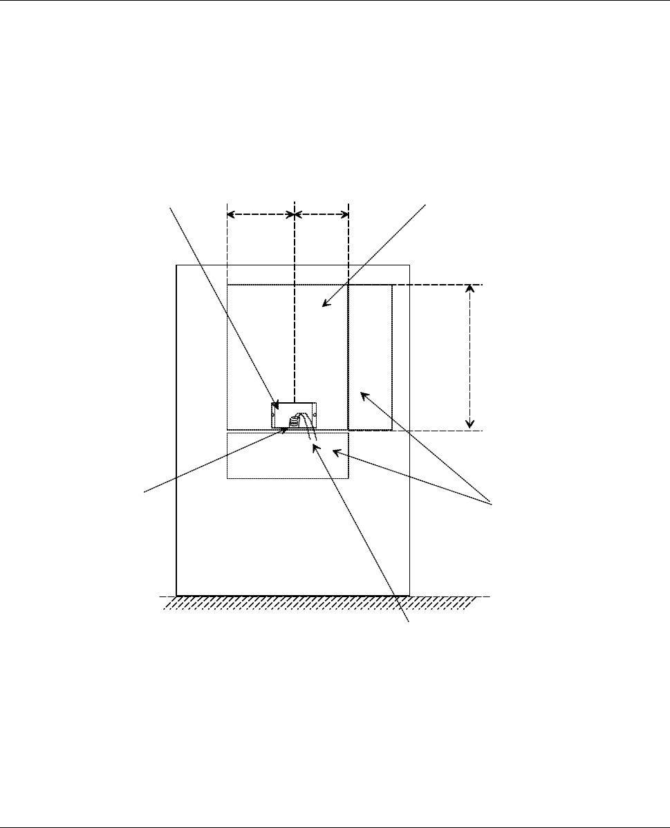
It is recommended that you attach the cables to wall box. The position
selected for mounting the box must satisfy the requirements laid down for the
mounting area and allow the necessary space for opening the box (see
Figure 1). In addition, there must be sufficient space to the right and rear of
the unit to allow access to the box with a screwdriver.
tube 14cm 12cm mounting area
encased
box
floor
cables
32cm
work area
Figure 1: Space requirements for mounting
Page 6 Electrical Connections
Electrical Connections
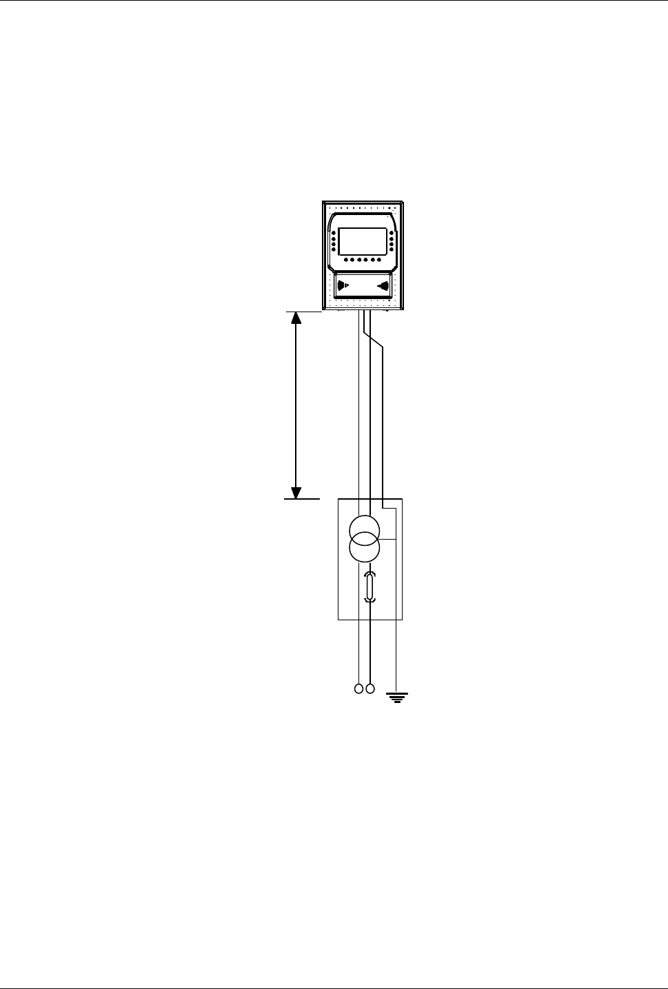
The TemaServer is powered at low voltage (12VAC) by means of a
transformer connected to the 115/230V 50/60Hz network switch. This switch
must be positioned prior to the TemaServer. The cables connecting the
transformer and the TemaServer must be at least AWG20 and no more than
10m long (see Figure 2).
10m max.
115/230V 12V
125mA
black
brown
yellow-green
230V 50Hz or
115V 60Hz
transformer
module
GROUND
yellow-green
oragne
gray
INOUT
Figure 2: Electrical connections
Cabling Arrangements Page 7
Cabling Arrangements
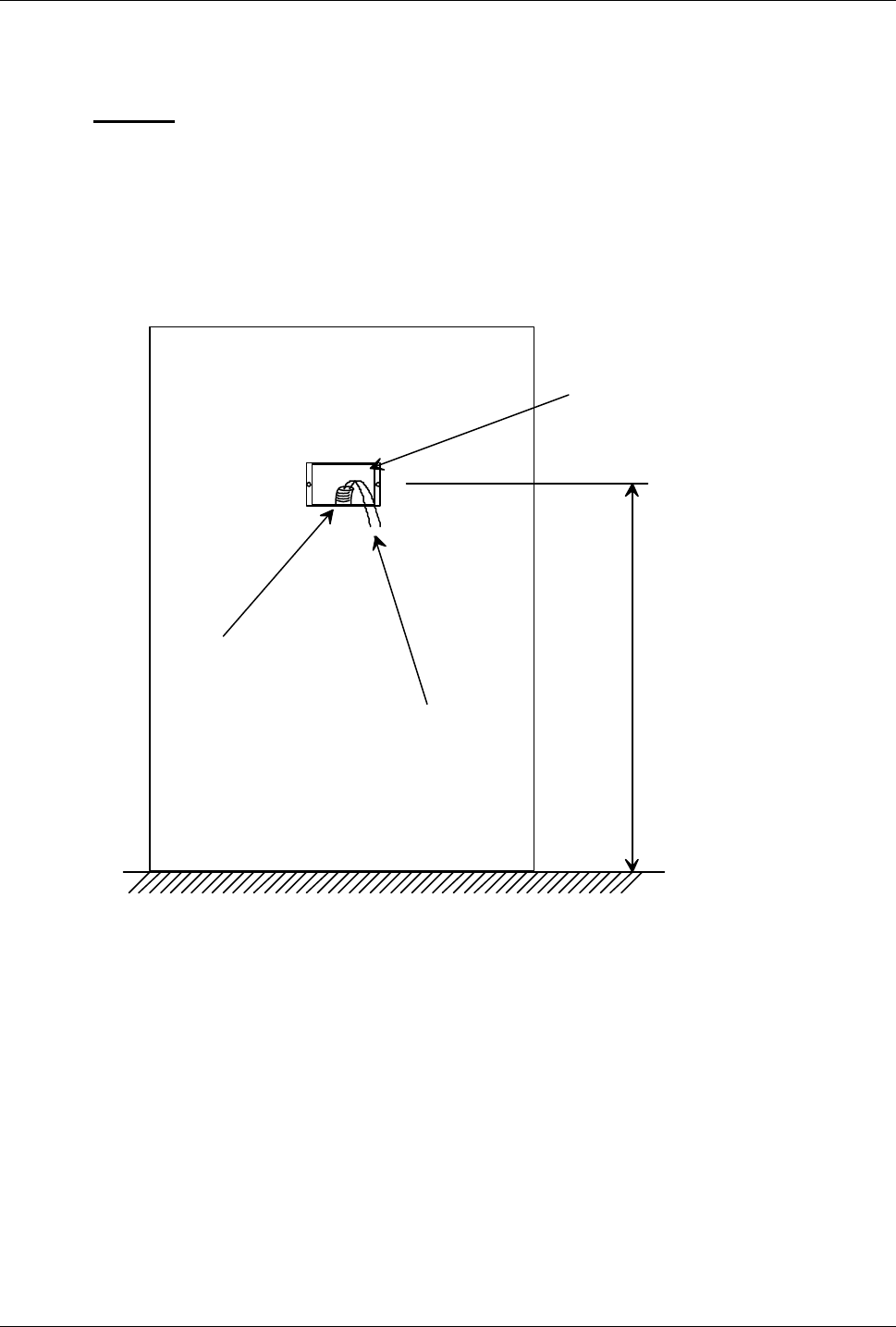
It is recommended that you attach the cables to wall box. The box must be
placed 120cm from the ground (see Figure 3).
It is strongly recommended that you run the LAN cable into a separate tube
from the one used for the 12V∼ power cable. If you wish to keep the LAN
cable and the 12V∼ power cable together, make sure that the 12V∼ cable is
shielded. You must not on any account attempt to route the LAN cable and
the primary power cable (230V∼) together.
encased box
tube
cables
floor
120 cm
Figure 3: Cabling arrangements
Page 8 Attaching the Terminal Support Plate
INSTALLATION
Attaching the Terminal Support Plate
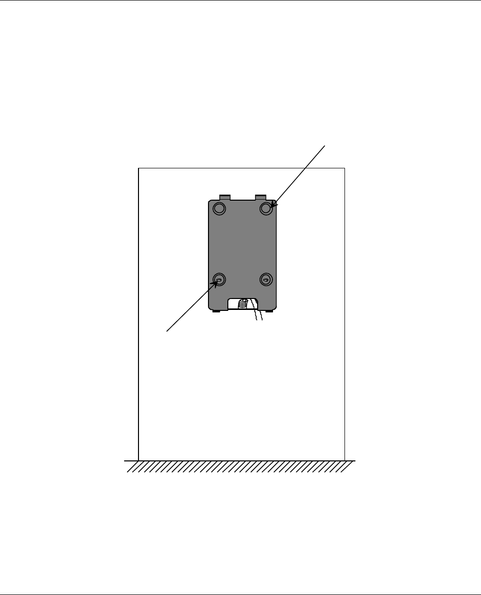
To attach the terminal support plate, drill two holes in the wall in which to
place the plastic anchors that hold up the support plate (see Figure 4). Make
sure that the box attached to the wall is aligned with the niche on the
lower part of the support plate (use a ∅ 6mm parallel tip flat head
screwdriver).
anchor
anchor
Figure 4: Terminal support plate
Hooking Up the Terminal Page 9
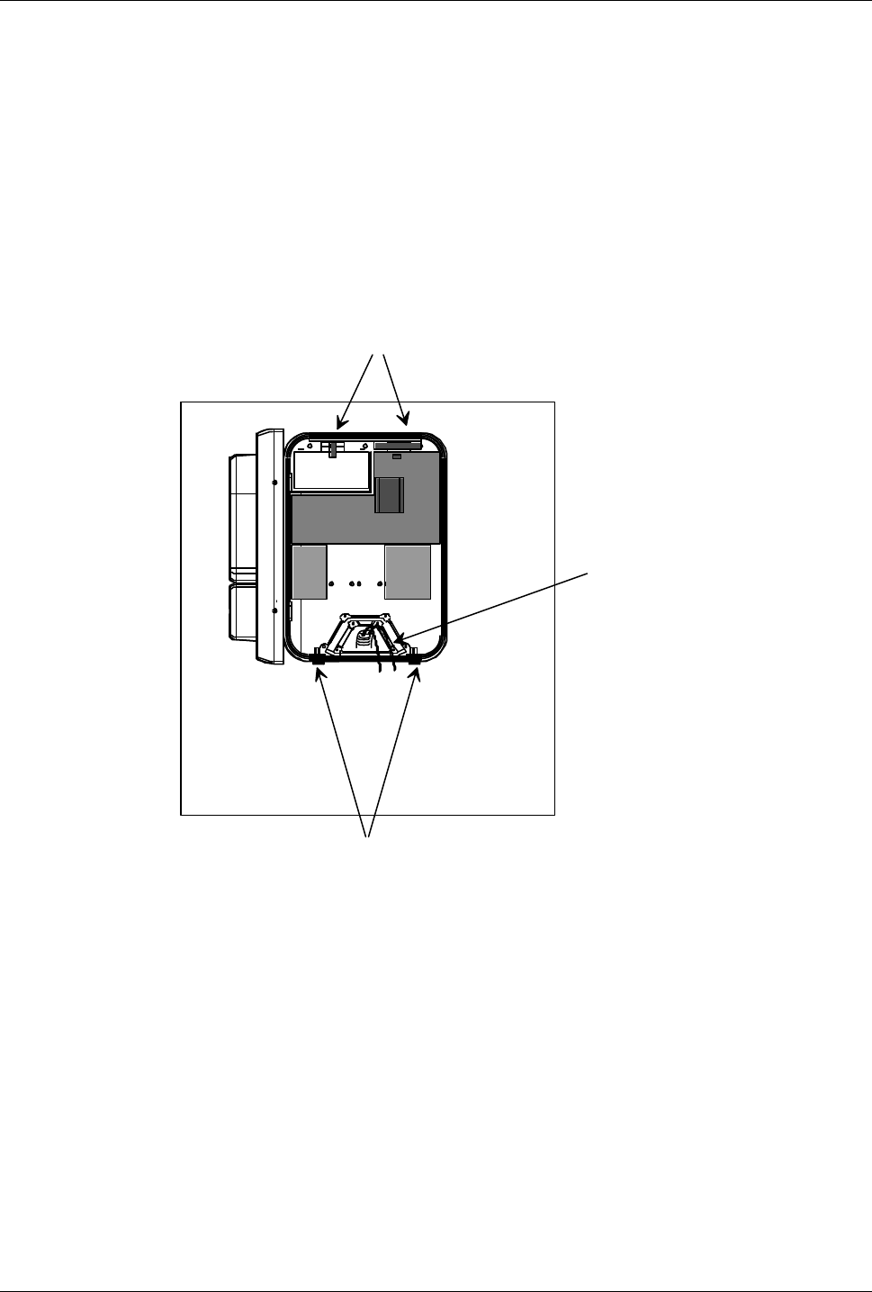
Hooking Up the Terminal
To hook up the terminal, follow the steps described below (see Figure 5):
1. Attach the upper part of the terminal to the upper hooks on the support
plate.
2. Insert the cables into the terminal through the specified openings.
3. Tighten the two screws that secure the terminal to the support plate (use a
∅ 6mm parallel tip flat head screwdriver).
1) Attach terminal to hooks
3) fasten the screws
2) Insert
cables
Figure 5: Hooking up the terminal
Page 10 Connecting the Cables
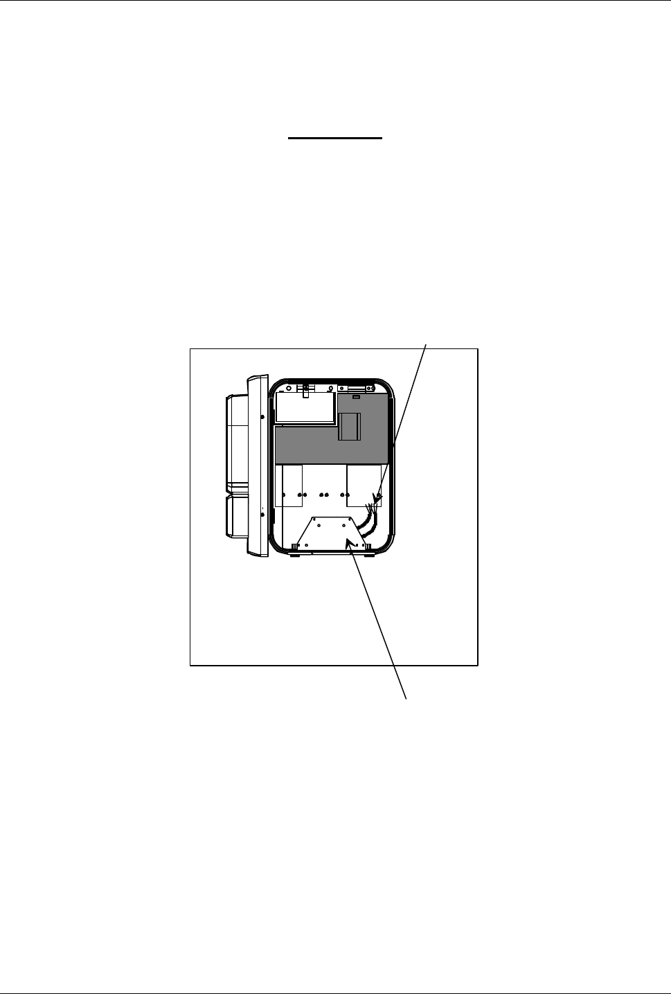
Connecting the Cables
To connect the cables, follow these steps:
1. Before connecting the cables, insert the power supply jumpers.
WARNING
Do not press the anti-opening tamper during installation and/or
maintenance of the unit.
2. Line up the cables with the grooves at the back of the terminal (see Figure
6) and screw in the small plate which serves as a cable clamp (use a ∅
5mm Philips screwdriver).
Fasten cable clamp
board (8 screws)
Lock cables
Figure 6: Connecting the cables
3. Attach the wire pin connectors to the terminals located on the lower part of
the terminal unit. (use a ∅ 3mm flat head screwdriver).
4. Insert the cable in the corresponding connector (see Figure 7) to complete
the connection to the LAN Ethernet 10BaseT (twisted pair).
Figure 9 illustrates the connections and settings of jumpers JP2 and JP3 on
the display control board. Make sure that both jumpers are in the position
shown in Figure 9 (MAG-TEK interface).
Connecting the Cables Page 11
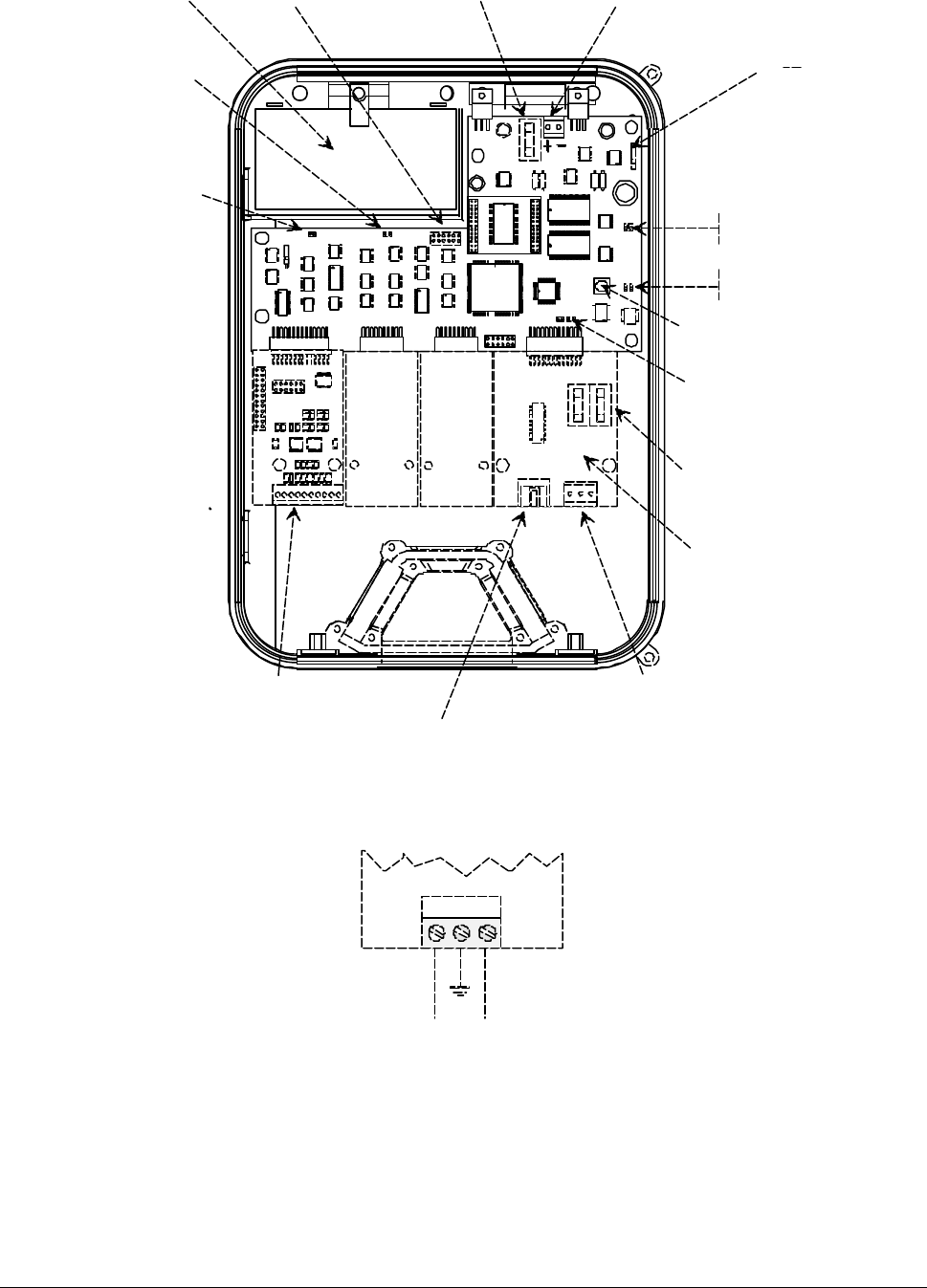
When 12V of electric current is supplied (see Figure 8), the terminal
commences operation and the green “RUN” LED lights up (see Figure 7)
tamper
Ethernet 10BaseT
power supply (12V)
Status LED
Power supply
fuses
Battery fuse (F1) Battery cable
RESET button
JP4,JP3 jumpers
Ethernet (test)
JTAG
P10 wall-tamper
(jumper)
P12 connector
for production
jumper -
LEAVE OPEN!
Battery
Collision (red)
RUN (green)
Plug-in Ethernet
I/O terminal box
TX (red)
RX (green)
Figure 7: Main circuit components
orange
green-yellow
grey
Figure 8: Close-up view of the 12V supply
Page 12 Connecting the Cables
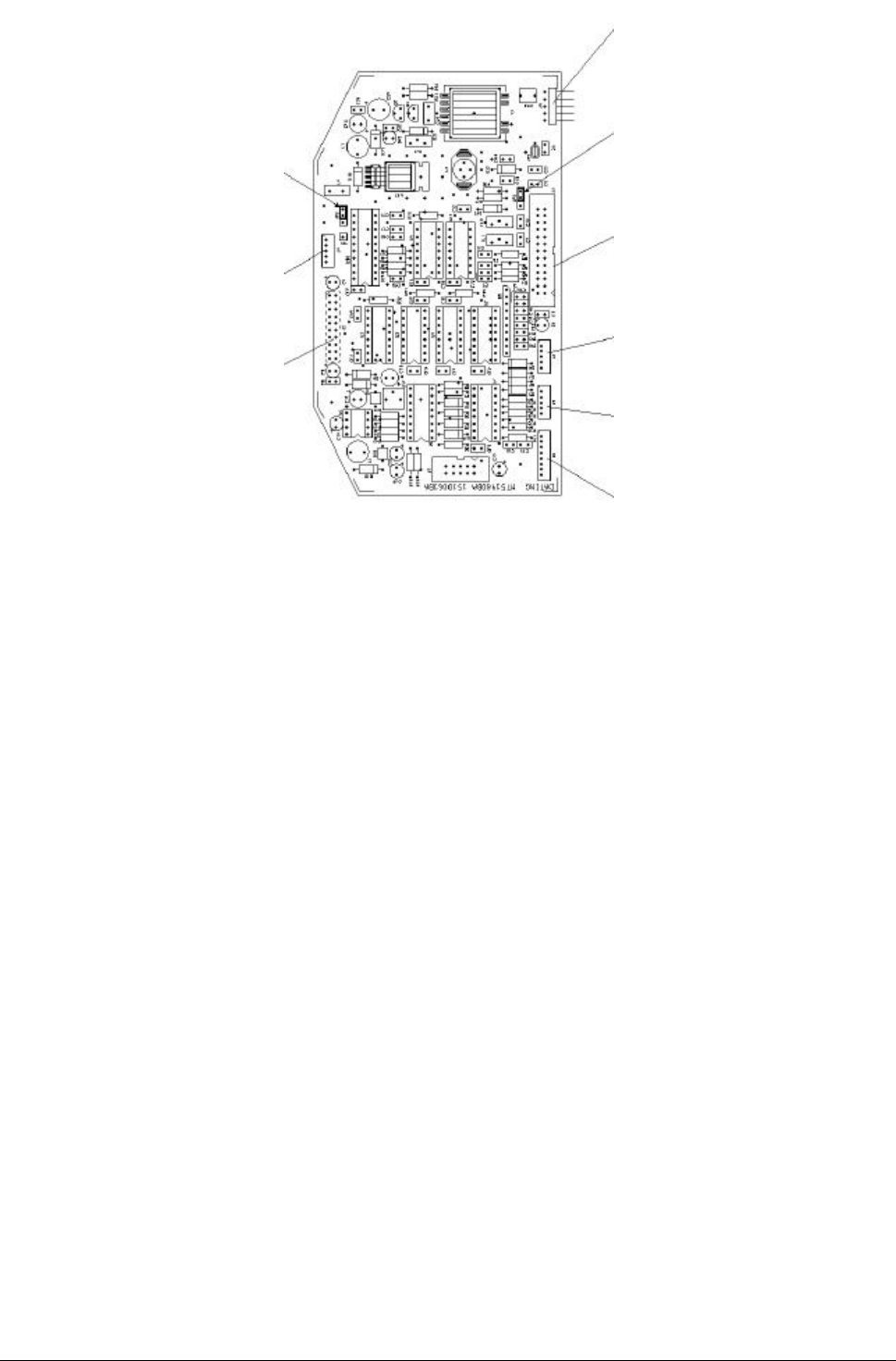
jumper JP3
pin 1-2 = MAG-TEK
pin 2-3 = Proxy
keyboard cable
(4 rightmost keys)
connection with
LCD controller
lamp cable for rear-
lighting of LCD
jumper JP2
pin 1-2 = MAG-TEK
pin 2-3 = bid
irectional
serial interface
TemaServer mother
board connection
keyboard cable
(4 leftmost keys)
keyboard cable
(6 central keys)
4x4 keyboard
(optional)
Figure 9: Display board details

Jumpers Page 13
Jumpers
For normal operation, configure the jumpers on the main board as specified
in Table 2.
Jumper Function Default state
P10 auxiliary tamper Inserted
P12 auto-update of
firmware Open
JP3 Ethernet full duplex Open
JP4 Ethernet loopback Inserted
Table 1: Configuration of jumpers on main board
Configure the jumpers on the display board as specified in Table 2.
Jumper Function Default state
JP2 data transmission inserted between pins 1
and 2
JP3 data receipt inserted between pins 1
and 2
Table 2: Configuration of jumpers on display board
Page 14 Auxiliary Connections
Auxiliary Connections
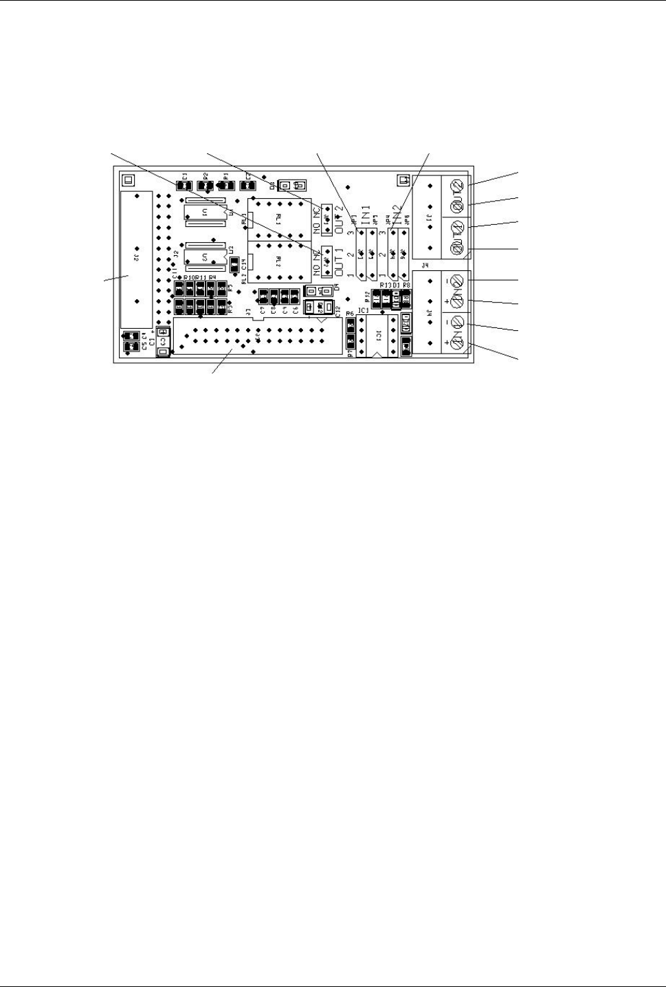
The I/O plug-in board features a connector that includes two opto-coupled
inputs and two relay outputs, as illustrated in Figure 10.
jumper jumper jumpers jumpers
relay 1 relay 2 input 1 input 2
connector to
mother
board
relay output 1
relay output 1
relay output 2
relay output 2
input 1 -
input 1 +
input 2 -
input 2 +
Connection to LCD control board
Figure 10: Auxiliary connections
Note: When the cables go externally, shielded cables must be used. The
cable’s shield must be connected to ground connector
You can define the operational mode of each relay by positioning the
appropriate jumpers as follows:
• Jumper «OUT1» between 12 (NO) for relay 1 normally open
• Jumper «OUT1» between 23 (NC) for relay 1 normally closed
• Jumper «OUT2» between 12 (NO) for relay 2 normally open
• Jumper «OUT2» between 23 (NC) for relay 2 normally closed
You can define the operational mode of each input by positioning the
appropriate jumpers as follows:
• Jumpers «IN1» between 12 for input 1 on dry contact
• Jumpers «IN1» between 23 for input 1 opto-coupled
• Jumpers «IN2» between 12 for input 2 on dry contact
• Jumpers «IN2» between 23 for input 2 opto-coupled
Closing the Terminal Page 15
Closing the Terminal
To close the terminal, follow these steps:
1. Connect both contacts of the battery cable to the battery
2. Make sure that the rubber gasket is correctly positioned.
3. Close the terminal cover by rotating it.
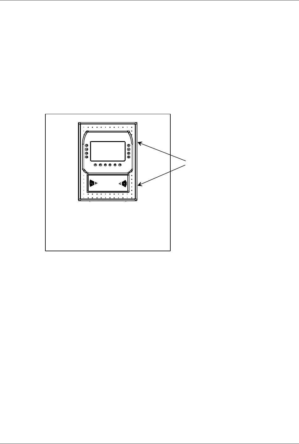
4. Fasten the cover with the two special screws (see Figure 11) located on
the side of the terminal (use a TORX anti-tamper TX10 screwdriver).
Fasten the
special screws
INOUT
Figure 11: Closing the terminal
Page 16 Applying the Entry/Exit Labels
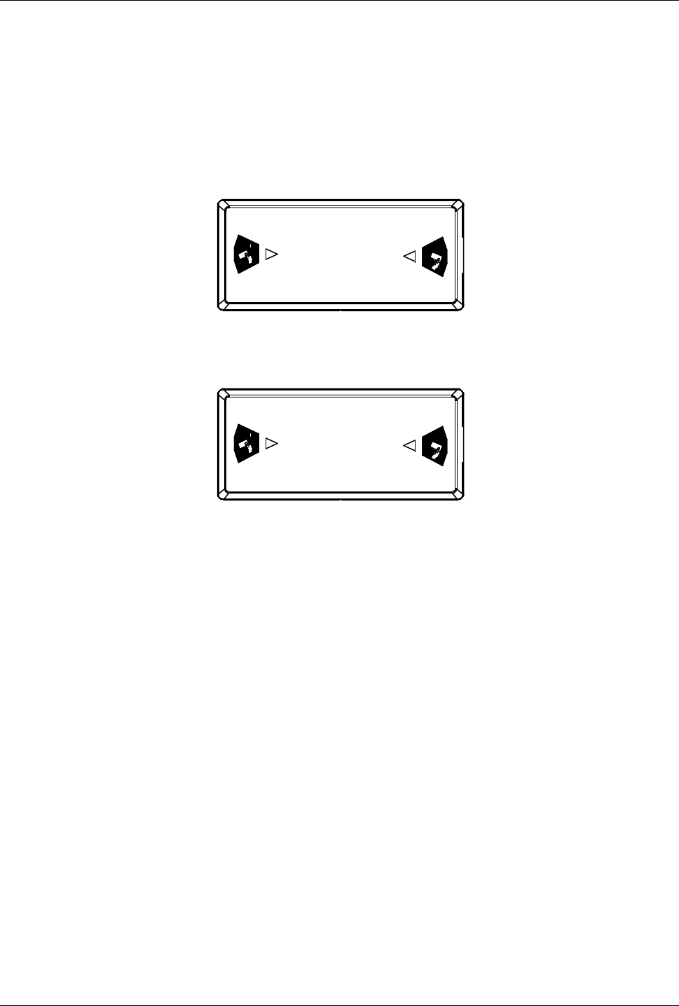
Applying the Entry/Exit Labels
Apply the two entry/exit labels to the magnetic reader according to the pre-
configured transit direction. Make sure that you place the labels in the
appropriate hollows (TS-Tax3/TS-Tax4: see details in Figure 12 and Figure
13).
IN
OUT
ß EXIT ENTRY à
Figure 12: Entry/exit labels
OUT
IN
ß ENTRY EXIT à
Figure 13: Entry/exit labels

TemaServer TS TAx3 (CTU-K03 code 1500064FA) Page 17
TECHNICAL SPECIFICATIONS
TemaServer TS TAx3
(CTU-K03 code 1500064FA)
Parameter Value
DC power supply 12VDC±15% 500mA nominal (6W)
600mA max (for fast battery recharge)
AC power supply 12VAC±15% 50Hz
500mA (nominal)
600mA max (for fast battery recharge)
Power supply via TRN01
Transformer 230VAC ±15% 50Hz
30mA nominal (7VA)
40mA max. (for fast battery recharge)
Weight (including frame) 3.5kg (+ transformer TRN01 = 500g)
Size 220x305x80 mm
IP Protection Rating IP55
Environmental
temperature for correct
operation
0…50 °C
LAN Ethernet
connection 10BaseT standard cable on RJ45
Proxy antennae Double antenna 125KHz for HID cards
Read distance 0…50mm
Expansions 2 slots for 1-unit plug-in cards
(or une 2-units plug-in card)
Relay outputs Number of outputs: 2
Max. load allowed:
50VDC 1A
Page 18 TemaServer TS TAx3 (CTU-K03 code 1500064FA)
Inputs Number of inputs: 2
• opto-coupled mode
resistance: 2.2 Kohm
logic level high:
>4 VDC (max. positive +18 VDC)
logic level low:
<1 VDC (max. negative –0.5 VDC)
• self powered mode (dry contacts)
open contact: > 2Kohm
closed contact: < 100 ohm (10mA)
Regulations compliance
Directive EMC 89/336/EEC, 92/31/EEC,
Directive Low Voltage 72/23/EEC, 93/68/EEC:
EN60950, EN55024, EN55022, EN61000-3-2/3,
EN 300 330
Includes a part with FCC-ID: HS9-CTU-K03
Spare Parts
Fuses F1 : 2A 250V delayed
F2 : 1A 250V delayed
F3 : 1A 250V delayed
Battery 6V 1.2 Ah code 1801026
Figure 14: TemaServer TS TAx3

TemaServer TS TAx4 (CTU-K04 code 1500087DA) Page 19
TemaServer TS TAx4 (CTU-K04 code 1500087DA)
Parameter Value
DC power supply 12VDC±15% 500mA nominal (6W)
600mA max (for fast battery recharge)
AC power supply 12VAC±15% 50Hz
500mA (nominal)
600mA max (for fast battery recharge)
Power supply via TRN01
Transformer 230VAC ±15% 50Hz
30mA nominal (7VA)
40mA max. (for fast battery recharge)
Weight (including frame) 3.5kg (+ transformer TRN01 = 500g)
Size 220x305x80 mm
IP Protection Rating IP55
Environmental
temperature for correct
operation
0…50 °C
LAN Ethernet
connection 10BaseT standard cable on RJ45
Proxy antenna Antenna 139KHz for WSE cards
Read distance 0…30mm
Expansions 2 slots for 1-unit plug-in cards
(or une 2-units plug-in card)
Relay outputs Number of outputs: 2
Max. load allowed:
50VDC 1A
Page 20 TemaServer TS TAx4 (CTU-K04 code 1500087DA)
Inputs Number of inputs: 2
• opto-coupled mode
resistance: 2.2 Kohm
logic level high:
>4 VDC (max. positive +18 VDC)
logic level low:
<1 VDC (max. negative –0.5 VDC)
• self powered mode (dry contacts)
open contact: > 2Kohm
closed contact: < 100 ohm (10mA)
Regulations compliance
Directive EMC 89/336/EEC, 92/31/EEC,
Directive Low Voltage 72/23/EEC, 93/68/EEC:
EN60950, EN55024, EN55022, EN61000-3-2/3,
EN 300 330
Includes a part with FCC-ID: C4P DR4201
Spare Parts
Fuses F1 : 2A 250V delayed
F2 : 1A 250V delayed
F3 : 1A 250V delayed
Battery 6V 1.2 Ah code 1801026
Figure 15: TemaServer TS TAx4

TemaServer TS Tax5 (CTU-K05 code 1500114DA) Page 21
TemaServer TS Tax5 (CTU-K05 code 1500114DA)
Parameter Value
DC power supply 12VDC±15% 500mA nominal (6W)
600mA max (for fast battery recharge)
AC power supply 12VAC±15% 50Hz
500mA (nominal)
600mA max (for fast battery recharge)
Power supply via TRN01
Transformer 230VAC ±15% 50Hz
30mA nominal (7VA)
40mA max. (for fast battery recharge)
Weight (including frame) 3.5kg (+ transformer TRN01 = 500g)
Size 220x305x80 mm
IP Protection Rating IP55
Environmental
temperature for correct
operation
0…50 °C
LAN Ethernet
connection 10BaseT standard cable on RJ45
Proxy antenna Antenna:
Exciter Field 125KHz
Receive 62.5Khz
For FlexPass Prox cards
Read distance 0…50mm
Expansions 2 slots for 1-unit plug-in cards
(or une 2-units plug-in card)
Relay outputs Number of outputs: 2
Max. load allowed:
50VDC 1A

Page 22 TemaServer TS Tax5 (CTU-K05 code 1500114DA)
Inputs Number of inputs: 2
• opto-coupled mode
resistance: 2.2 Kohm
logic level high:
>4 VDC (max. positive +18 VDC)
logic level low:
<1 VDC (max. negative –0.5 VDC)
• self powered mode (dry contacts)
open contact: > 2Kohm
closed contact: < 100 ohm (10mA)
Regulations compliance
Directive EMC 89/336/EEC, 92/31/EEC,
Directive Low Voltage 72/23/EEC, 93/68/EEC:
EN60950, EN55024, EN55022, EN61000-3-2/3,
EN 300 330
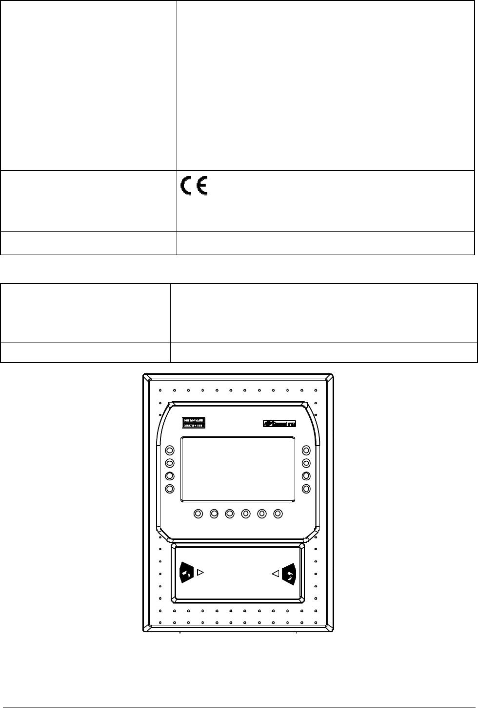
Includes a part with FCC-ID: HS9-CTU-K05
Spare Parts
Fuses F1 : 2A 250V delayed
F2 : 1A 250V delayed
F3 : 1A 250V delayed
Battery 6V 1.2 Ah code 1801026
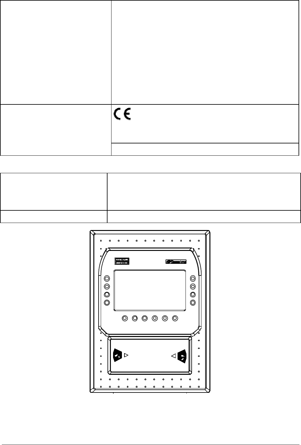
Figure 16: TemaServer TS Tax5

TemaServer TS Tax7 (CTU-K07 code 1500118AA) Page 23
TemaServer TS Tax7 (CTU-K07 code 1500118AA)
Parameter Value
DC power supply 12VDC±15% 500mA nominal (6W)
600mA max (for fast battery recharge)
AC power supply 12VAC±15% 50Hz
500mA (nominal)
600mA max (for fast battery recharge)
Power supply via TRN01
Transformer 230VAC ±15% 50Hz
30mA nominal (7VA)
40mA max. (for fast battery recharge)
Weight (including frame) 3.5kg (+ transformer TRN01 = 500g)
Size 220x305x80 mm
IP Protection Rating IP55
Environmental
temperature for correct
operation
0…50 °C
LAN Ethernet
connection 10BaseT standard cable on RJ45
Proxy antenna Antenna 13.56MHz for Mifare cards
Read distance 0…30mm
Expansions 2 slots for 1-unit plug-in cards
(or une 2-units plug-in card)
Relay outputs Number of outputs: 2
Max. load allowed:
50VDC 1A

Page 24 TemaServer TS Tax7 (CTU-K07 code 1500118AA)
Inputs Number of inputs: 2
• opto-coupled mode
resistance: 2.2 Kohm
logic level high:
>4 VDC (max. positive +18 VDC)
logic level low:
<1 VDC (max. negative –0.5 VDC)
• self powered mode (dry contacts)
open contact: > 2Kohm
closed contact: < 100 ohm (10mA)
Regulations compliance
Directive EMC 89/336/EEC, 92/31/EEC,
Directive Low Voltage 72/23/EEC, 93/68/EEC:
EN60950, EN55024, EN55022, EN61000-3-2/3,
EN 300 330
Includes a part with FCC-ID: HS9-CTU-K07
Spare Parts
Fuses F1 : 2A 250V delayed
F2 : 1A 250V delayed
F3 : 1A 250V delayed
Battery 6V 1.2 Ah code 1801026
Figure 17: TemaServer TS Tax7

Optional Parts Page 25
Optional Parts
TORX TX10 screwdriver Code 1500108AA

Ιντερνετ: ηττπ://ωωω.τεµαλινε.χοµ