Ademco DD15 DD15 User Manual DD15 Installation Instructions
Honeywell International Inc DD15 DD15 Installation Instructions
Ademco >
User Manual
Part #DD15
Part #DD15 Installation Instructions 6/30/2016
1
DD15 Daikin VRV Interface Module Installation Instructions
Table of Contents Introduction ......................................................................................1
Specification ....................................................................................2
Safety Precautions ............................................................................3
System Overview .............................................................................4
Mounting ..........................................................................................7
Wiring ..............................................................................................9
Start-Up ..........................................................................................13
Inputs & Outputs ............................................................................14
Model & Part Numbers ..................................................................15
Regulatory Compliance .................................................................16
Introduction
Daikin North America LLC and Honeywell have jointly developed an
organically integrated system which allows Honeywell’s INNCOM
Integrated Room Automation system to provide direct digital control of
the Daikin Variable Refrigerant Volume (VRV) heat recovery system.
This is an industry first solution that provides the hotelier an intelligent
integrated room automation system capable of connecting all of the
guestroom devices to control room temperature, lighting drapes and
amenities, in-room 3rd party integration of door locks, as well as connect
to the INNcontrol 3 software on a central server over the Deep Mesh
Network, with the efficiency of Daikins VRV system.

Part #DD15
Part #DD15 Installation Instructions 6/30/2016
2
Features
A seamless energy management solution, with integrated VRV
capability tailored specifically for hospitality
Provides a more energy efficient solution with lower operating
costs than traditional FCU systems
Maximizes dehumidification capability, and significantly reduces
mechanical noise over traditional FCU systems
In-room 2.4Ghz RF wireless network communications
Software control of the field settings for the Daikin VRV in door
unit (IDU)
Error reporting from the Daikin system to the INNcontrol 3
application on the central server
Over-the-air loadable for easy installation, commissioning, and
maintenance
Ideal for new installation and retrofit
Compact interface module
Best-in-class offerings from Honeywell and Daikin
Specification
Parameter Specification
Input Voltage (P4) 16VDC
DC Output (P3) 12V, 30mA (50mA Peak)
Current Consumption Typical 100mA. See the DD15 Digital Output section for application
specific current consumption.
Bind Switch Recessed switch used for commissioning and binding (S1)
Indicator LED’s Diagnostic LED (green), Transmit activity (Yellow), Receive activity
(Red)
Communications S5bus for wired bus communication, 2.4Ghz wireless RF Transceiver for
Deep Mesh RF communication
Dimensions 84.5mm (L) x 47mm (W) x 29mm (H)
Maximum Operating Temperature (0°C to 40°C)
Maximum Storage Temperature -40°C – 70°C
Relative Humidity 5 – 90%RH Non-Condensing
Approvals FCC 47CFR PT 15.247 Issued:2004/10/01 Operation within the bands
902-928MHz, 2400-2483.5MHz and 5725-5850MHz
RSS-247 Issue: 2015/05/22 Issue 1 Digital Transmission Systems
(DTSs), Frequency Hopping Systems (FHSs) and License-Exempt
Local Area Network (LE-LAN) Devices
FCC 47CFR PT 15 SPT B Issued:2013/01/28 Title 47 CFR Part 15
Subpart B: Unintentional Radiators
ICES 003 Issued: 2012/08/01 Spectrum Management and
Telecommunications Interference-Causing Equipment Standard
EN 300 328:2015 V1.9.1 EMC & Radio Spectrum Matters (ERM);
Wideband Transmission Systems Data Transmission Equipment
Operating in the 2.4GHz ISM Band & Using Wide Band Modulation
Techniques Harmonized EN for Article 3.2- R&TTE Directive

Part #DD15
Part #DD15 Installation Instructions 6/30/2016
3
Parameter Specification
EN 300 489-1 V1.9.2 Electromagnetic compatibility and Radio spectrum
Matters (ERM); Electromagnetic compatibility (EMC) standard for radio
equipment and services; Part 1: Common technical requirements
EN 301 489-17 Electromagnetic compatibility and radio spectrum
matters (ERM); Electromagnetic Compatibility (EMC) standard for radio
equipment; Part 17: Specific Conditions for broadband data
transmission systems –V2.1.1
N 55022 Issue:2010/12/01 Information Technology Equipment-Radio
Disturbance Characteristics – Limits and Methods of Measurement,
Includes COR 2011/10/01
EN 55024 Issue: 2010/11/01 Information Technology Equipment –
Immunity Characteristics Limits and Methods of Measurement.
Safety
Precautions
The following safety precautions should be observed during the
installation start-up to prevent personal injury or equipment damage:
Observe national and local electrical codes.
Observe voltage and current limits marked on the DD15
Observe voltage and current limits and rating when wiring to the
Daikin VRV IDU and X18A/X35A terminal boards
Assumption is that the installer has a working knowledge of the
INNCOM system
Replacing Legacy
Device
A single DD15 replaces the legacy solution of a RTD-LCINC and a PC-
485, which provided the integration between Daikin VRV and the
INNCOM by Honeywell system.
Shutting down power to the Daikin VRV unit will be required when
disconnecting the RTD-LCINC and the PC-485. Follow the wiring
instructions section when installing the DD15.
NOTE:
The form factor of the DD15 allows for a different mounting
application.
Part #DD15
Part #DD15 Installation Instructions 6/30/2016
4
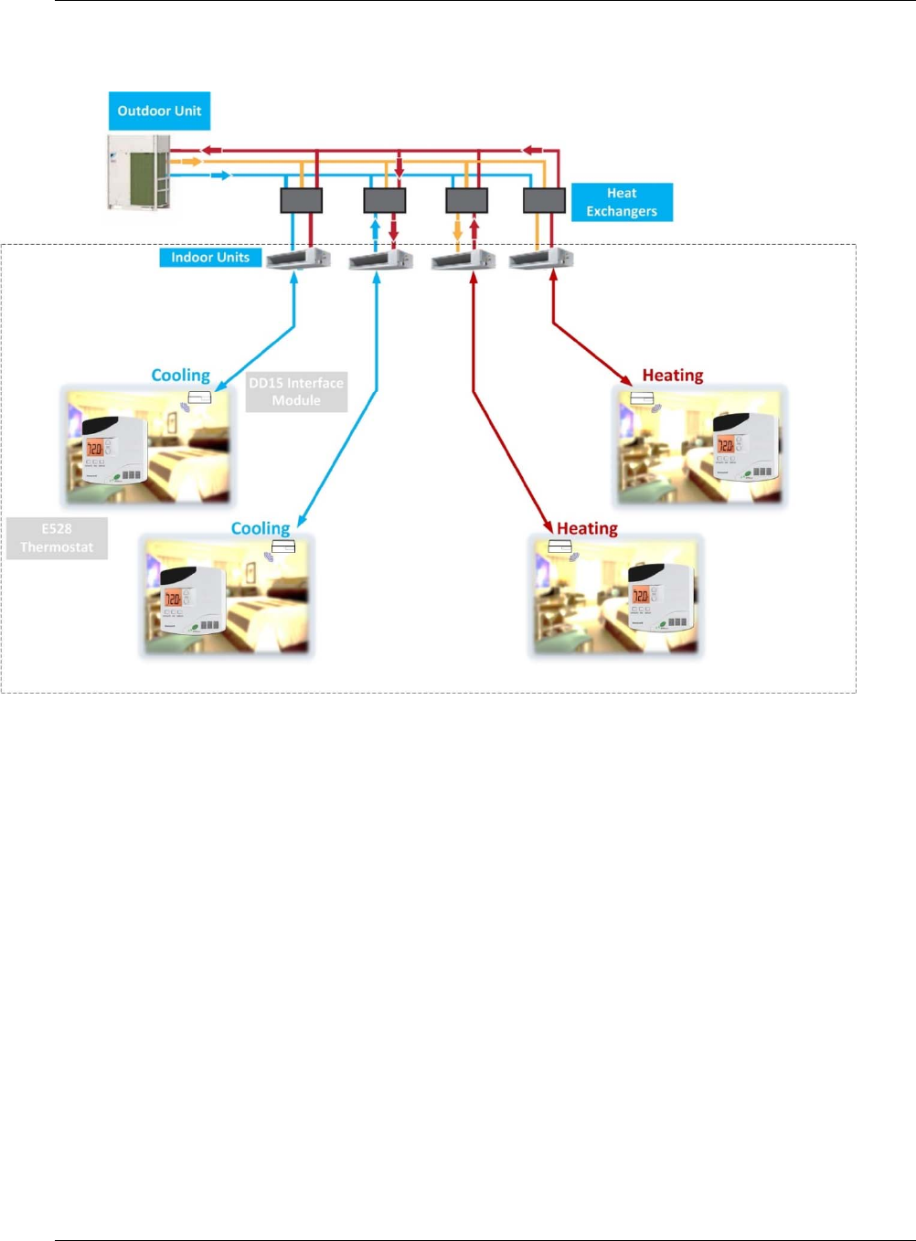
System Overview
Figure 1 Standard VRV Integration Overview
Honeywell’s INNCOM e528 or e527 thermostat replaces the standard
Daikin VRV room controller for the heat recovery system. Daikin’s heat
recovery solution provides an alternative to a chiller plant and is
becoming more widely accepted in the hospitality market. The e528 or
e527 thermostat is the “intelligent” device capable of linking ancillary
sensors and serving as an information gateway. For example, coupled
with a magnetic door switch (wired or wireless), motion detectors and
other devices, the e528 or e527 thermostat becomes the center of a
highly effective Energy Management System application,
communicating EMS information requirements from the guestroom to
the central server. When connected to the INNcontrol server over a wired
or wireless backhaul network, a centrally controlled EMS package is
created. Through interfaces with other devices and sensors, the solution
provides the following functions:
Guestroom HVAC diagnostics
Remote room occupancy indication

Part #DD15
Part #DD15 Installation Instructions 6/30/2016
5
Central Electronic Lock
Humidity Management
Outside temperature display
Peak demand load shedding
Property/Building Management System (PMS/BMS) interface
Deep Mesh
Wireless
Communication
The DD15 interface module is equipped with a 2.4 GHz wireless RF
transceiver for Deep Mesh RF communications. This provides the
capability to wirelessly communicate to Honeywell’s INNCOM e528 or
e527 thermostat. This additionally provides the capability to wirelessly
over-the-air load the device for software updates and configuration
changes.
NOTE:
The DD15 is not intended to be used as a general purpose RF
media gateway or protocol converter.
Parameter Specification
RF Data Rate 250kbps
Antenna Type SMT
Indoor Range 100ft
Outdoor/ RF line-of-sight
range
1000ft+
Transmit Power 10mW (+18dBm)
Receive Sensitivity -94.6dBm
Frequency Band 2.4Ghz
Encryption AES-128
Protocol 802.15.4
Frequency Channels 11-26
Table 1 Deep Mesh RF Radio Attributes
Part #DD15
Part #DD15 Installation Instructions 6/30/2016
6
Figure 2 Typical Wireless Installation
Part #DD15
Part #DD15 Installation Instructions 6/30/2016
7
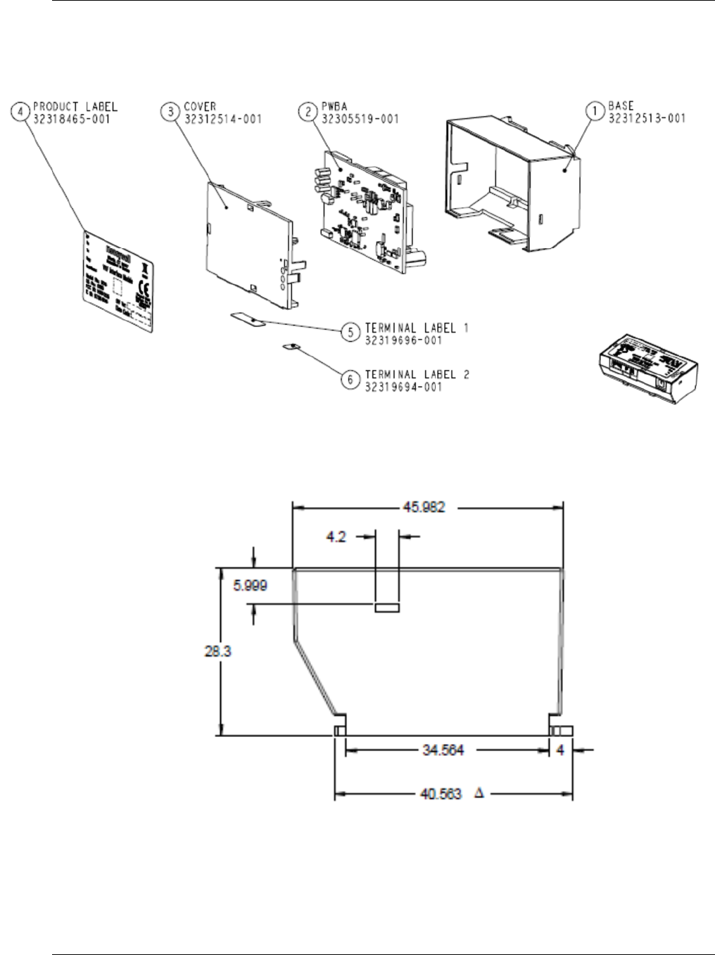
Mounting
Use the following details and precautions to mount the device.
Figure 3 DD15 Exploded Diagram
Figure 4 Side view
Part #DD15
Part #DD15 Installation Instructions 6/30/2016
8
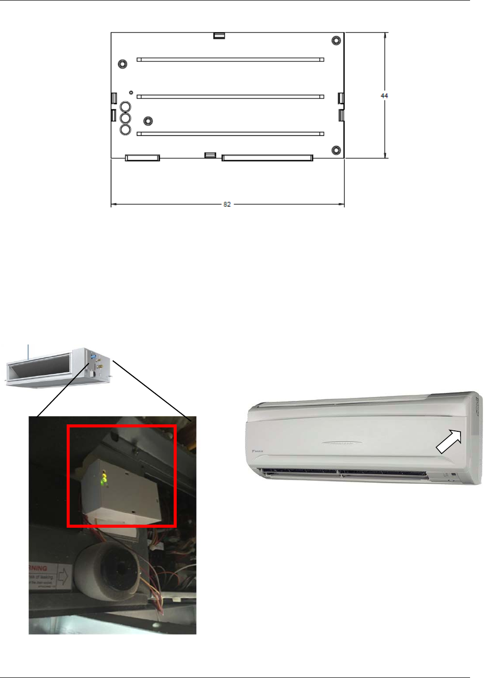
Figure 5 Top view
Mount the DD15 in any orientation to a suitable flat surface using the provided double sided tape
(once adhesive is applied, you will not be able to reposition device). Can be mounted inside or
outside of the indoor unit. DD15 must not be mount in a metal enclosure as not to interfere with
RF communications.
EXTERNAL MOUNTING WALL MOUNTED, FXAQ DAIKIN UNIT
Example of mounting
Figure 6 Mounting locations

Part #DD15
Part #DD15 Installation Instructions 6/30/2016
9
Wiring
Use the following information to properly wire the device. Follow all
precautions and read all instructions prior to beginning any work.
CAUTION!
Electrical Shock Hazard! Can cause severe injury, death or
property damage. Disconnect power supply and load power
sources before beginning wiring or making wiring connections
to prevent electrical shock or equipment damage.
Running Long
Cable Lengths
The DD15 is typically installed in our around the Daikin IDU using the
provided harnesses. When wiring the Daikin P1P2 bus or DIII –net line
communication cable should be non-shielded, 18AWG, standard non-
polar cabling. For further detailed wired requirements of the Daikin IDU,
please contact Daikin directly.
Table 2 DD15 Cable and Conductor Attributes
DD15 Headers &
Pins
P1 In-Circuit Programming Header – Main Micro
Pin Signal Function
1-8 Various Programming header for programming the main micro. Use 03-0501
Table 3 DD15 In-Circuit Programming Header
P2 External Temperature Sensor
Pin Signal Function
Color
Parameter Specification
24AWG Bare Solid Copper
Insulation FRPE (PVC), 100% FEP (Plenum)
Ripcord Under Jacket
Jacket Flame Retardant PVC
Impedance 100 +/- 15 Ohms
Mutual Capacitance, Max. nf/1000ft 17.1
DC Resistance, Max. Ohms/100ft 28.6

Part #DD15
Part #DD15 Installation Instructions 6/30/2016
10
1 GND Ground Brown
2 NTC 10K NTC (NU) Red
3 GND Ground Orange
Honeywell recommends to use the following:
PN: 04-1094.MOD external thermistor
PN: 04-1096.MOD ruggedized external thermistor
Table 4 DD15 External Temperature Sensor Header
P3 S5bus In / S5bus Out
Pin Signal Function Color
1 GND Ground Brown
2 VEE 12VDC Red
3 S5bus Communication Bus (NU) Orange
Table 5 DD15 S5bus and Input Voltage Header
P4 P1/P2 Interface
Pin Signal Function Color
1 GND Common Brown
2 VIN Power(+16VDC) Red
3 P2 Daikin Communication Bus Orange
4 P1 Daikin Communication Bus Yellow
5 IN-1 Dry Contact Input (NU) Green
6 OUT-1 Open Collector Output (NU) Blue
Table 6 Daikin IDU Interface Header
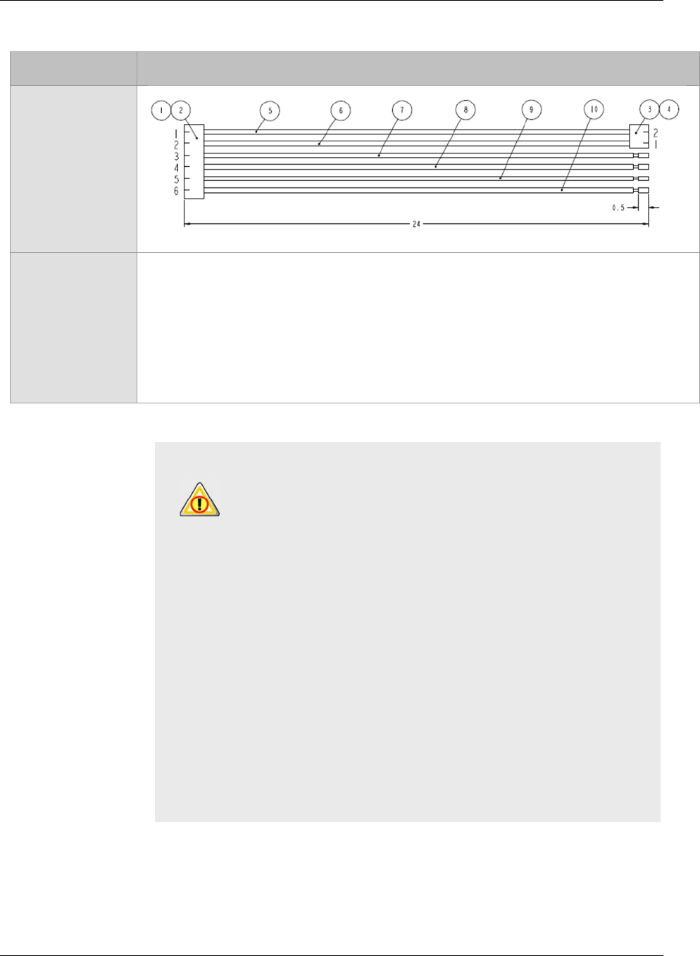
Figure 7 Six conductor wire harness
Pins 1-6
Part #DD15
Part #DD15 Installation Instructions 6/30/2016
11
DD15 Harnesses
Part Number Drawing
32315379 (x1)
62-1465
CAUTION!
1. Don’t connect DD15 to the VRV indoor unit before verifying
the Daikin VRV system is operating error free using the iTouch
Manager (iTM).
2. Connect the 6-wire harness to its corresponding port on the
DD15.
3. Connect the 3-wire harness to the S5bus port on the DD15
(NOTE: S5Bus not used in wireless application)
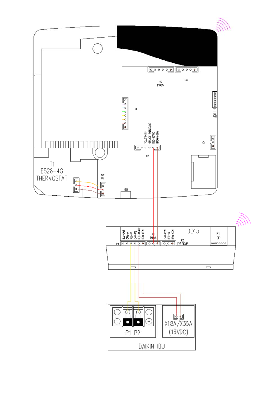
4. The orange and yellow wires of the 6-wire harness are to
connect to Daikin indoor unit P1P2 terminal (P1 P2 connection
is non-polarized)
5. From the 3-wire harness, connect the brown wire to ground,
red wire to 12VDC and the orange wire to the S5bus terminals
on the thermostat, H7.
6. From the 6-wire harness, plug the brown and red wire
connector (image below) to the X18A or X35A socket (16V
DC) on the Daikin indoor unit PCB.
Part #DD15
Part #DD15 Installation Instructions 6/30/2016
12
3 conductor harness
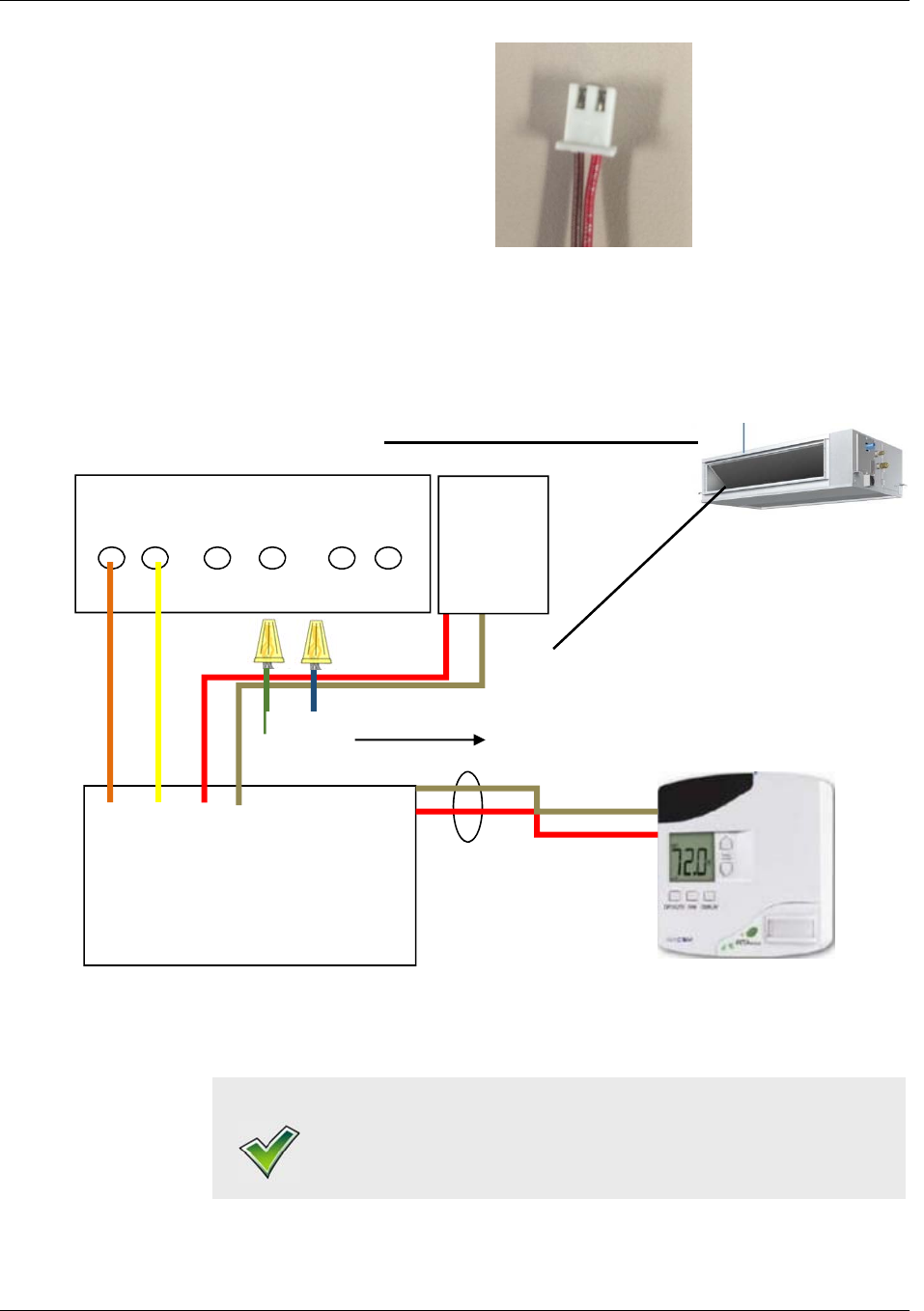
Figure 8 16VDC power connector
Figure 9 Wiring example
NOTE:
The green and blue wires are capped off and not used in this
configuration.
DAIKIN IDU
P1 P2 F1 F2 T1 T2
P1 P2 Pwr S5bus
DD15
X18A/X
35A
16VDC Daikin VRV IDU
E528
S5Bus

Part #DD15
Part #DD15 Installation Instructions 6/30/2016
13
Start-Up
The DD15 device will power up without user interaction, and operate in
default mode until communication with the thermostat is established. The
diagnostic LED will fast blink on start up. The system will return to the
last configured temperature setting, and update upon first interaction.
The DD15 will send all necessary field settings to the Daikin IDU, such
as fan always, and remote measured room temperature (temperature
measured from the INNCOM e528 or e527 thermostat).
Check installation
NOTE:
Continue for wired communication only, for wireless
communication complete RF BIND PROCEDURE, first!
1. Power up the Daikin indoor unit first.
2. Red power LED is lit
3. Set the thermostat to the highest setpoint check if the indoor
unit engages heating
4. Set a setpoint like 65F lower than the room temperature and
check if the indoor unit coordinate providing cooling.
5. The Daikin indoor unit may need 1 to 5 minutes for cool/heat
mode changeover.
6. Confirm the room temperature input at iTM is matching with
what ream at e528.
7. Change the fan speed at the thermostat and confirm the fan
speed change at indoor unit and iTM.
DD15 RF Bind
Procedure
NOTE:
S1 is used for teaching the DD15 a specific device address or
function map. Use a paper clip to access S1 for teaching the
address.
1. The DD15 uses a “reverse binding” procedure to acquire
network information from the thermostat, meaning that the
device will signal the thermostat that it wants the information.
Besides the information set in the thermostat in the steps above,
the DD15 requires a map of network components, complete with
unique address. This information is typically carried in the I/O
Map.
2. Place the thermostat in Service Parameter mode as above. Go to
the Io (I/O Map Teach) parameter and press the DISPLAY
button (for e528.4G) or OFF/AUTO to view the value. Set the Io
value to the desired I/O Map number. Do NOT press the
thermostat’s DISPLAY or OFF/AUTO button.
3. For the e528.4G, press OFF/AUTO and the LCD will display
bnd.
4. Using a small point (e.g., the end of a straightened paper clip),

Part #DD15
Part #DD15 Installation Instructions 6/30/2016
14
press the recessed Reset/Bind switch (S1) on the DD15 once.
5. The thermostat sends a bind offer to the DD15. If accepted, the
thermostat will buzz loudly. The DD15 will reset.
6. Test the DD15 functionality.
DD15 Power
Outage and
Restoration
All INNCOM devices have an onboard non-volatile memory, which is
used to store the operating state of the DD15 in case of a power outage.
With restoration of communications or power, the unit will initiate a
brief power-up sequence. After power-up is complete, the unit will return
to the last know configuration state.
Inputs & Outputs
Wiring Input
In the case of using an external thermistor with the DD15, plug the
thermistor into the Ext Temp socket on the DD15.
Wiring Output
In the case the DD15 will control other heat source.
Troubleshoot
DD15 LED function
LED Function
Green Slow Blink Pattern (once per second): Indicates the DD15 is in standard operation
mode, is powered, and running.
Medium Speed Blink Pattern: The DD15 has accepted the teach-mode command,
and will reset.
Solid On Pattern: DD15 is in failure mode.
Sold Off Pattern: The DD15 is not powered on, or if powered on, the DD15 is in
failure mode.
Red Fast Blink Pattern: Indicates P1/P2 received data activity
Yello
w Fast Blink Pattern: Indicates P1/P2 transmitted data activity
All Daikin fault codes are communicated to the DD15 via the
P1P2 protocol. These codes are then passed to the INNCOM
Server PC to be displayed in IC3 for the hotel engineers.
Error code U5
1. System Transmission error, the DD15 is not communicating with
the IDU.
2. Confirm the DD15 has power.

Part #DD15
Part #DD15 Installation Instructions 6/30/2016
15
Model & Part
Numbers
The part numbers provided below should be used to order the appropriate
parts.
DD15 DD15 Daikin Direct VRV interface module
Thermostats:
e528 01-9911-A0L7-xxx Honeywell’s INNCOM thermostat
e527 201-527xxx Honeywell’s INNCOM thermostat

Part #DD15
Part #DD15 Installation Instructions 6/30/2016
16
Regulatory
Compliance
This device has been tested and found to be in compliance with the requirements stated below.
Federal
Communications
Commission (FCC)
This device complies with part 15 of the FCC Rules. Operation is subject to the following two
conditions: (1) This device may not cause harmful interference, and (2) this device must accept any
interference received, including interference that may cause undesired operation.
NOTE!
This equipment has been tested and found to comply with the limits for Class
B digital devices, pursuant to Part 15 of the FCC Rules. These limits are
designed to provide reasonable protection against harmful interference in a
residential installation. This equipment generates uses and can radiate radio
frequency energy and, if not installed and used in accordance with the
instruction manual, may cause harmful interference to radio communications.
However, there is no guarantee that interference will not occur in a particular
installation. If this equipment does cause harmful interference to radio or
television reception, which can be determined by turning the equipment off
and on, the user is encouraged to try to correct the interference by one or
more of the following measures:
Re-orient or relocate the receiving antenna
Increase the separation between the equipment and receiver
Connect the equipment to an outlet on a different circuit from the receiver
Consult the dealer or an experienced radio/TV contractor for help.
CAUTION!
Any changes or modifications not expressly approved by
Honeywell could void your authority to operate this equipment.
Canadian Dept. of
Comm.(DOC)
NOTE!
This device complies with Industry Canada licence-exempt RSS standard(s).
Operation is subject to the following two conditions: (1) this device may not
cause interference, and (2) this device must accept any interference, including
interference that may cause undesired operation of the device.
C’et appareil est conforme la norme d'Industrie Canada exempts de licence
RSS. Son fonctionnement est soumis aux deux conditions suivantes: (1) c’et
appareil ne peut pas provoquer d'interférences, et (2) c’et appareil doit
accepter toute interférence, y compris les interférences qui peuvent causer un
mauvais fonctionnement de la dispositifWaste Electrical & Electronic
Equipment
Customers are advised to dispose of this product at the end of its useful life according to applicable
local laws, regulations, and procedures.

Part #DD15
Part #DD15 Installation Instructions 6/30/2016
17
INNCOM® is a registered trademark of Honeywell International
The material in this document is for information purposes only. The content and the product it describes
are subject to change without notice. INNCOM makes no representations or warranties with respect to this document.
In no event shall INNCOM be liable for technical or editorial omissions or mistakes in this document, nor shall it be liable
for any damages, direct or incidental, arising out of or related to the use of this document. No part of this document
may be reproduced in any form or by any means without prior written permission from INNCOM.
Copyright © 2016 by Honeywell International, Inc.. All Rights Reserved.
INNCOM
277 West Main Street
Niantic, CT 06357
Phone: 800.543.1999
Fax: +1.860.739.4460
www.inncom.com