Ademco RTU-B07 Temakey Modular Terminal User Manual Tema1 0 TKMOD IM 1 0 US
Honeywell International Inc Temakey Modular Terminal Tema1 0 TKMOD IM 1 0 US
Ademco >
manual

Modular Terminal
Modular TerminalModular Terminal
Modular Terminal
Installation Manual
Installation ManualInstallation Manual
Installation Manual

TABLE OF CONTENTS Page 3
Modular terminal
TABLE OF CONTENTS
TABLE OF CONTENTSTABLE OF CONTENTS
TABLE OF CONTENTS
FCC NOTICE............................................................................. 4
PRELIMINARY OPERATIONS
PRELIMINARY OPERATIONSPRELIMINARY OPERATIONS
PRELIMINARY OPERATIONS ........................
................................................
........................5
55
5
Mounting Instructions .............................................................. 5
Arranging the Cable Tubes and Junction Boxes............................ 6
Cabling: Recommendations .................................................. 6
Electrical Connections .............................................................. 8
LONWORKS Data Cables......................................................... 9
Mounting the Unit on the Wall ................................................. 11
Horizontal Assembly – Single Module .................................. 11
Horizontal Assembly – Triple Module ................................... 12
Combined Assembly - Single and Triple Modules ................... 13
Fastening the Cables ........................................................ 15
Vertical Assembly............................................................. 16
Channeling the Cables from the Bottom of the Box .............. 17
INSTALLATION
INSTALLATIONINSTALLATION
INSTALLATION ................................
................................................................
.........................................
..................
.........18
1818
18
Combining the Modules ........................................................... 18
Reader ............................................................................ 18
Keyboards ....................................................................... 18
Display ............................................................................ 18
Terminals......................................................................... 19
Terminals with Keyboards.................................................. 19
Interactive Terminals ........................................................ 20
Interactive Terminals with Keyboards ................................. 20
Attaching the Modules to the Wall........................................... 21
Applying the Entry/Exit Labels.................................................. 22
Identification via Bar Code ....................................................... 23
Version: 1.0 US

FCC NOTICE Page 4
TECHNICAL DATA
TECHNICAL DATATECHNICAL DATA
TECHNICAL DATA ................................
................................................................
....................................
........
....24
2424
24
Summary of Modular Devices................................................... 24
RTU-B07 (Proxy Reader for HID Cards)..................................... 25
RTU-C01 (Alphanumeric LCD Module) ....................................... 26
RTU-C02 (Graphic LCD Module) ............................................... 27
RTU-T01 (Numeric Keyboard Module)........................................ 28
Optional Parts ....................................................................... 29
FCC NOTICE
FCC NOTICEFCC NOTICE
FCC NOTICE
NOTE: This equipment has been tested and found to comply with the limits
for a Class B digital device, pursuant to Part 15 of FCC Rules. These limits
are designed to provide reasonable protection against harmful interference
in a residential installation. This equipment generates, uses and can radiate
radio frequency energy and, if not installed and used in accordance with the
instructions, may cause harmful interference to radio communications.
However these is no guarantee that interference will not occur in a particular
installation.
If this equipment does cause harmful interference to radio or television
reception, which can be determined by tuning the equipment of and on, the
user is encouraged to try to correct the interference by one or more the
following measures:
-- Reorient or relocate the receiving antenna.
-- Increase the separation between the equipment and receiver.
-- Connect the equipment into an outlet on a circuit different from that to
which the receiver is connected.
-- Consult the dealer or an experienced radio/TV technician for help.
Mounting Instructions Page 5
PRELIMINARY OPERATIONS
Mounting Instructions
Mounting InstructionsMounting Instructions
Mounting Instructions
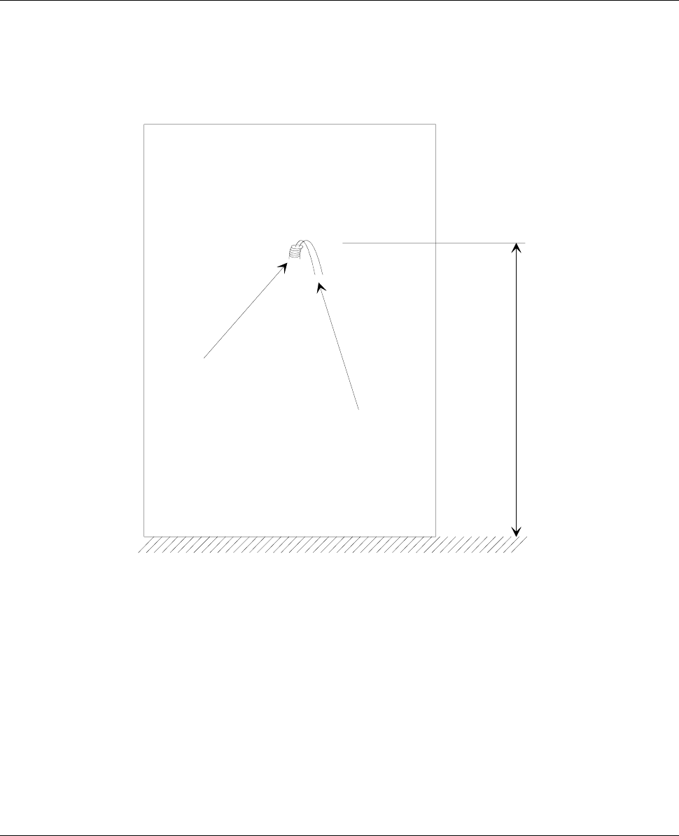
The cables are attached to an encased box. Make sure that you
place the box at a height of 120cm from the floor (see Figure 1).
tube
cables
120 cm
floo
r
Figure 1: Space requirements for mounting
Arranging the Cable Tubes and Junction Boxes Page 6
Arranging the Cable Tubes and Junction
Arranging the Cable Tubes and JunctionArranging the Cable Tubes and Junction
Arranging the Cable Tubes and Junction
Boxes
BoxesBoxes
Boxes
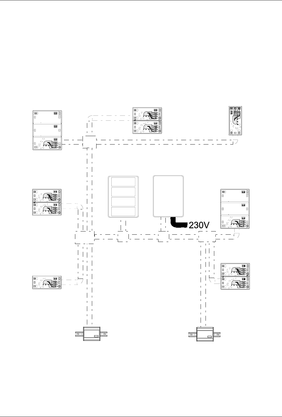
All the cables consist of 4 wires that must be connected in parallel
from one node to the next. It is possible to link nodes in free topology,
i.e. by means of a star or bus configuration.
Cabling: Recommendations
Cabling: RecommendationsCabling: Recommendations
Cabling: Recommendations
Figure 2 provides an example of a typical free topology installation.
TemaServer
TemaPower
Figure 2: Example of a free topology installation
Arranging the Cable Tubes and Junction Boxes Page 7
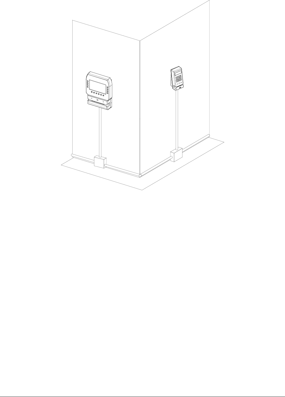
If you want to mount the tubes on the surface of the walls, it is
advisable to place the junction boxes under each terminal (see
example in Figure 3).
Figure 3: Location of the junction boxes

Electrical Connections Page 8
Electrical Connections
Electrical ConnectionsElectrical Connections
Electrical Connections
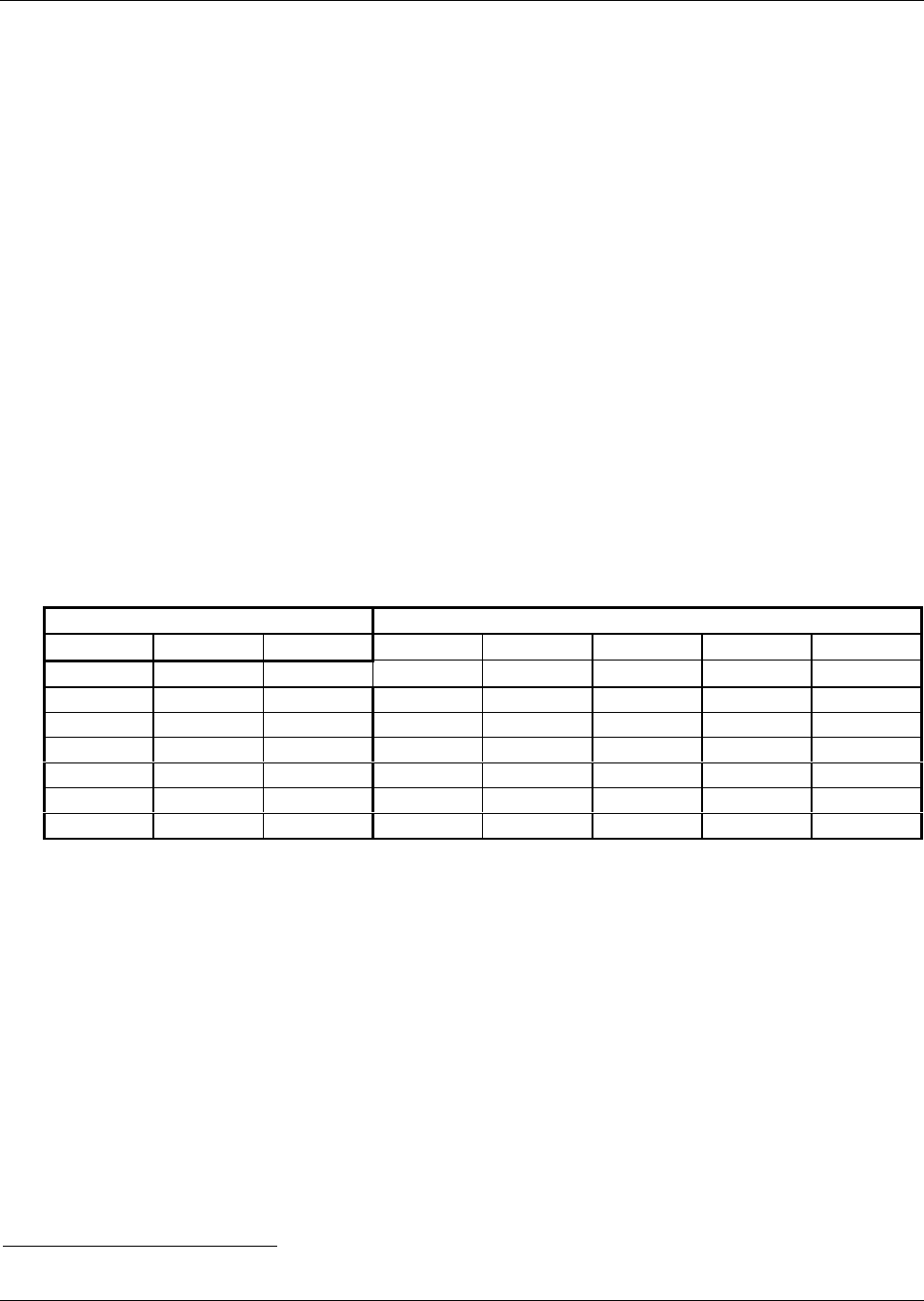
The RTU is powered at low voltage (12VDC 120mA) by a battery-
operated power supply module (RTU-Qxx). When determining the
correct size for power cables, refer to the table below.
Type of cable Length (m) in relation to effective load
AWG mm2 ohm/Km 100 [mA] 200 [mA] 500 [mA] 1 [A] 2 [A] 5 [A]
12 3,3 5,7 1754 87
7
351 175 88 35
14 2 8,8 1136 568 22
7
114 5
7
23
16 1,3 14 714 35
7
143713614
180,9214762389548241
0
20 0,6 34 294 14
7
59 29 15 6
22 0,35 52 19
2
96 38 19 1
0
4
24 0,2 85 118 59 24 1
2
62
LONWORKS( Data Cables Page 9
L
LL
LON
ONON
ONW
WW
WORKS
ORKSORKS
ORKS Data Cables
Data Cables Data Cables
Data Cables
• The LONWORKS 1 data cable must be twisted pair
• In a free topology configuration, the sum total of the sections must
not exceed 500m
• In a bus configuration, the sum total of the sections must not
exceed 2700m
• In a free topology configuration, activate the 50ohm terminator by
placing the appropriate jumper on the FTT10A plug-in of the CTU-
PLG06 board inside the TemaServer
• In a bus configuration, place two terminators (with resistance
values of 100ohm 1% ½W) at each end of the bus
• Check that the length of the LONWORKS data cable corresponds
to the norms indicated in Table 1.
Type of cable Length [m] in relation to cable capacity
AWG mm2 Ohm/Km 50nF/Km 100nF/Km 200nF/Km 500nF/Km 1uF/Km
12 3,3 5,7 2676 1892 1338 846 598
14 2 8,8 2153 1523 1077 681 482
16 1,3 14 1707 1207 854 540 382
18 0,9 21 1394 986 697 441 312
20 0,6 34 1096 775 548 346 245
22 0,35 52 886 626 443 280 198
24 0,2 85 693 490 346 219 155
Table 1: Length/capacity of LONWORKS data cables (m)
1 LONWORKS® is a trademark of Echelon Corporation

LONWORKS( Data Cables Page 10
• The FTT10A Echelon v1.2 User Guide recommends the cables
indicated in Table 2.
Manufacturer and
model
AWG Connection to bus -
maximum total length [m]
Connection in free topology –
maximum node-node length
max. [m]
Belden 85102 16 2700 500
Belden 8471 16 2700 400
Level IV (twisted pair,
typically solid and
unshielded)
22 1400 400
JY (St) 2x2x0.8 (4-wire
helical twist, solid
shielded)
20 900 320
Table 2: Recommended LONWORKS cables
Mounting the Unit on the Wall Page 11
Mounting the Unit on the Wall
Mounting the Unit on the WallMounting the Unit on the Wall
Mounting the Unit on the Wall
Horizontal Assembly – Single Module
Horizontal Assembly – Single ModuleHorizontal Assembly – Single Module
Horizontal Assembly – Single Module
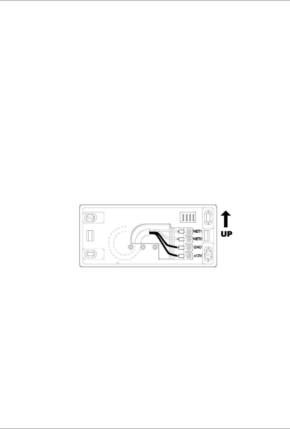
To assemble the unit in a horizontal position, follow these steps:
1. Drill two holes in the wall (to accommodate the 2 plastic dowels),
so that the frame will cover the hole through which the cables
pass.
2. Insert the cables in the cable clamp without pulling out the screws.
3. Use the dowels to fasten the frame to the wall. Make sure that
the lamellar connector is in the UP position.
4. Adjust the length of the cables so that they protrude by ~10cm
from the wall, and fasten them to the cable crimp.
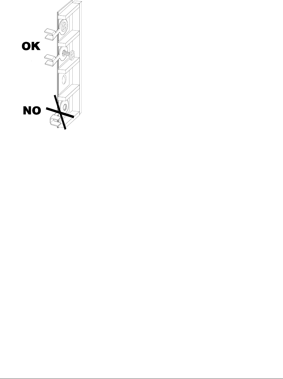
5. Fasten the cable crimp to the contacts in the direction shown in
Figure 4.
6. Place the remainder of the cable inside the frame and lock the cable
clamp.
Figure 4: Wall position — horizontal position (single module)
Mounting the Unit on the Wall Page 12
Horizontal Assembly – Triple Module
Horizontal Assembly – Triple ModuleHorizontal Assembly – Triple Module
Horizontal Assembly – Triple Module
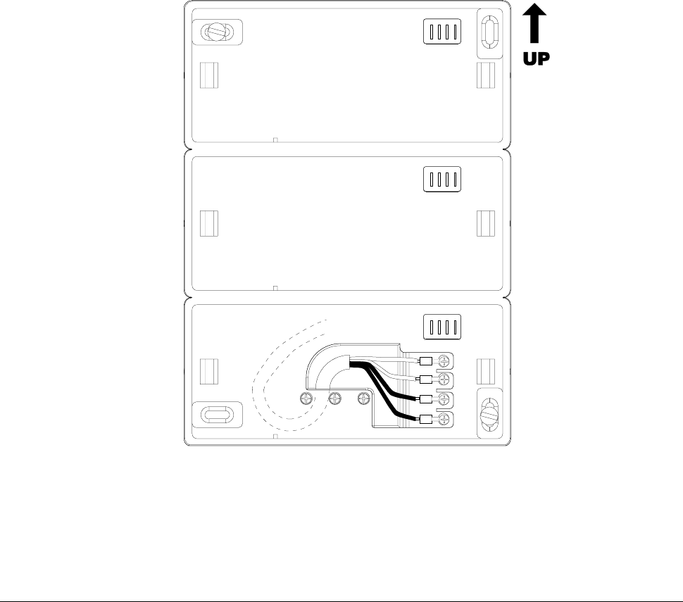
To assemble the unit in a horizontal position, follow these steps:
1. Drill two holes in the wall (to accommodate the 2 plastic dowels),
so that the frame will cover the hole through which the cables
pass.
2. Insert the cables in the cable clamp without pulling out the screws.
3. Use the dowels to fasten the frame to the wall. Make sure that
the lamellar connector is in the UP position.
4. Adjust the length of the cables so that they protrude by ~10cm
from the wall, and fasten them to the cable crimp.
5. Fasten the cable crimp to the contacts in the direction shown in
Figure 5.
6. Place the remainder of the cable inside the frame and lock the cable
clamp.
NET1
NET2
GND
+12V
Figure 5: Wall position — horizontal position (triple module)
Mounting the Unit on the Wall Page 13
Combined Assembly - Single and Triple Modules
Combined Assembly - Single and Triple ModulesCombined Assembly - Single and Triple Modules
Combined Assembly - Single and Triple Modules
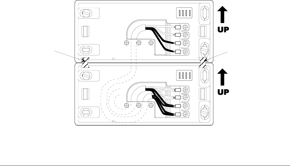
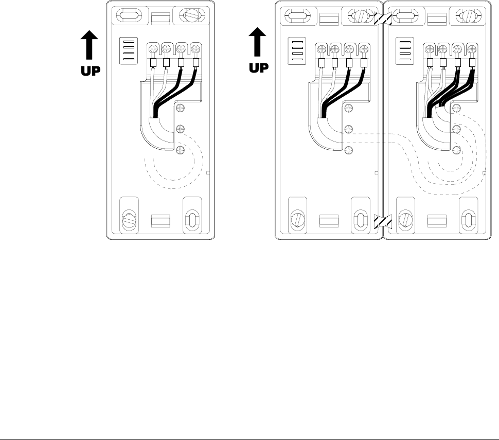
A combined wall assembly of single and triple modules allows you to
create units consisting of 2, 4 and 5 units. This procedure consists
of the following steps:
1. Drill the necessary holes in the wall (2 plastic dowels for each
module), so that the lower plate will cover the hole through which
the cables pass.
2. Insert the cables in the cable clamp without pulling out the screws.
3. Link the frames together by inserting the two enclosed attachment
clips at the rear of the frames (see Figure 6 and Figure 7).
4. Use the dowels to fasten the frame to the wall. Make sure that
the lamellar connector is in the UP position.
5. Adjust the length of the cables so that they protrude by ~10cm
from the wall, and fasten them to the cable crimp.
6. Intertwine the terminators of the cables from the wall and the
extension cable terminators, and fasten them to the cable crimps.
7. Fasten the cable crimp to the contacts in the direction shown in
Figure 6 and Figure 7.
8. Place the remainder of the cable inside the frame and lock the cable
clamp.
NET1
NET2
GND
+12V
NET1
NET2
GND
+12V
Attachment
clip Attachment
clip
Figure 6: Combined assembly of two single module wall units
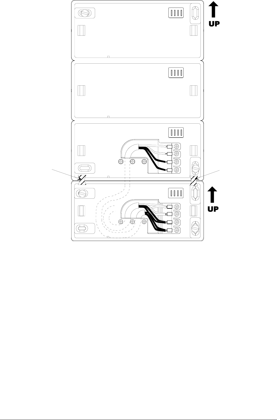
Mounting the Unit on the Wall Page 14
NET1
NET2
GND
+12V
NET1
NET2
GND
+12V
Attachment
clip
Attachment
clip
Figure 7: Combined assembly of single and triple module wall units
Mounting the Unit on the Wall Page 15
Fastening the Cables
Fastening the CablesFastening the Cables
Fastening the Cables
Fasten the cable clamps to the cable bar so that the cables are
arranged towards the inside of the frame (see Figure 8).
CONNECTIONS
NET1 (green)
NET2 (yellow)
GND (black)
+12V (red)
Figure 8: Fastening the cables
Mounting the Unit on the Wall Page 16
Vertical Assembly
Vertical AssemblyVertical Assembly
Vertical Assembly
To assemble the unit in a vertical position, follow these steps:
1. Drill two holes in the wall (to accommodate the 2 plastic dowels),
so that the frame will cover the hole through which the cables
pass.
2. Insert the cables in the cable clamp without pulling out the screws.
3. Use the dowels to fasten the frame to the wall. Make sure that
the lamellar connector is in the UP position.
4. Adjust the length of the cables so that they protrude by ~10cm
from the wall, and fasten them to the cable crimp.
5. Fasten the cable crimp to the contacts in the direction shown in
Figure 9.
6. Place the remainder of the cable inside the frame and lock the cable
clamp.
NET1
NET2
GND
+12V
NET1
NET2
GND
+12V
NET1
NET2
GND
+12V
Figure 9: Wall position — vertical assembly
Mounting the Unit on the Wall Page 17
Channeling the Cables from the Bottom of the Box
Channeling the Cables from the Bottom of the BoxChanneling the Cables from the Bottom of the Box
Channeling the Cables from the Bottom of the Box
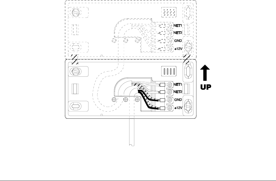
As an alternative, you can channel the cables so that they exit from
the bottom of the frame. This alternative procedure consists of the
following steps:
1. Drill a hole in the wall so that the hole from which the cables exit is
in the center of the lower plate.
2. Break off the lower removable tab from the upper support.
3. Break off the upper and lower tab from the lower support.
4. Insert both the cables from the wall and the remainder of the cable
in the cable clamp (be careful not to pull out the screws).
5. Use the dowels to attach the frame to the wall.
6. Adjust the length of the cables so that they protrude by ~10cm
from the wall.
7. Roll up the terminators of the cables from the wall and the
extension cables, and fasten them to the cable crimps (see Figure
10).
8. Fasten the cable crimp to the contacts in the direction shown in
Figure 10.
9. Place the remainder of the cables inside the frame and lock the
cable clamps.
Figure 10: Channeling the cables from the bottom of the box
Combining the Modules Page 18
INSTALLATION
Combining the Modules
Combining the ModulesCombining the Modules
Combining the Modules
Each TemaKey consists of one or more RTU modules that must be
positioned and connected to their respective wall attachment frames
(RTU-Sxx) as indicated in the table below.
Reader
ReaderReader
Reader
Code Grouping Horizontal Vertical Notes
TK-S07
1 x RTU-B07
1 x RTU-S01
Weight=0.45Kg
Power=0.8W
Current=60mA
Keyboards
KeyboardsKeyboards
Keyboards
Code Grouping Horizontal Vertical Notes
TK-S31
1 x RTU-T01
1 x RTU-S01
Weight=0.4Kg
Power=0.4W
Current=30mA
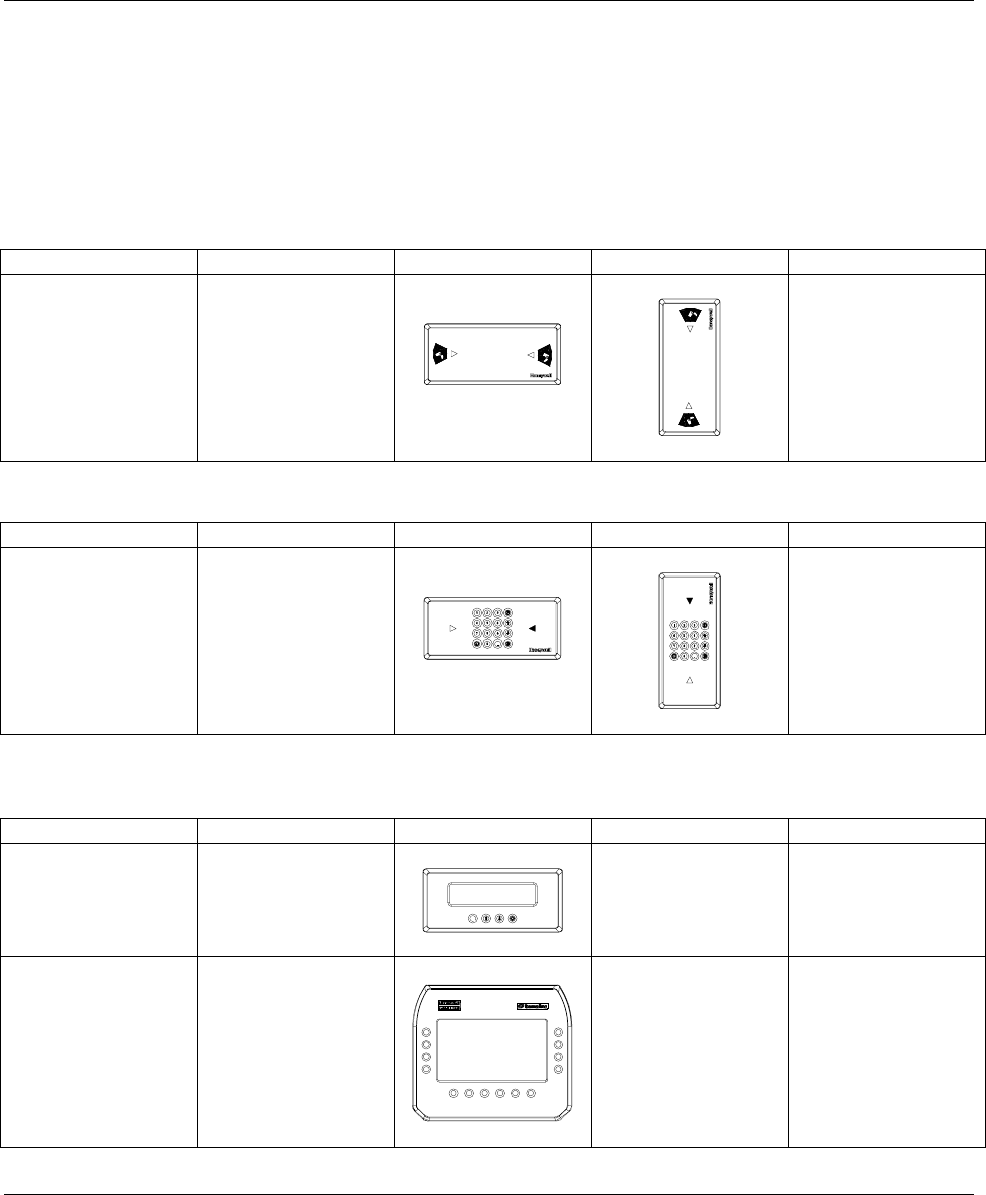
Display
DisplayDisplay
Display
Code Grouping Horizontal Vertical Notes
TK_S21
1 x RTU-C01
1 x RTU-S01
NO Weight=0.45Kg
Power=1.9W
Current=140mA
TK-S22
1 x RTU-C02
2 x RTU-S01
NO
Weight=0.95Kg
Power=5.2W
Current=380mA
Combining the Modules Page 19
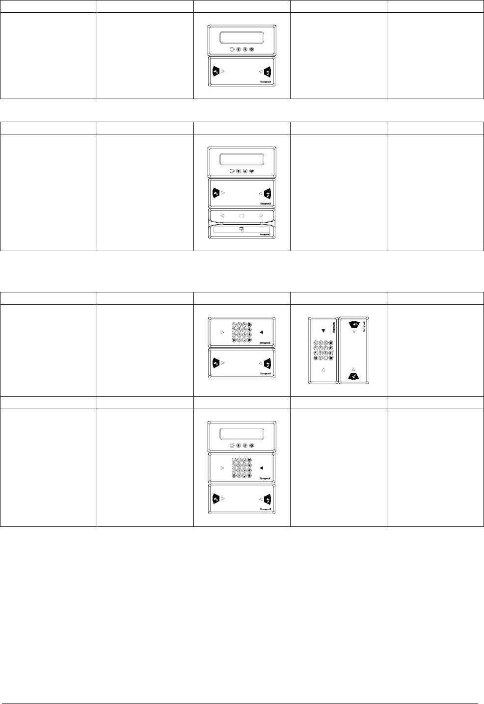
Terminals
TerminalsTerminals
Terminals
Code Grouping Horizontal Vertical Notes
TK-D07
1 x RTU-C01
1 x RTU-B07
2 x RTU-S01 NO
Weight=0.9Kg
Power=2.7W
Current=200mA
Code Grouping Horizontal Vertical Notes
TK_T09
1 x RTU-C01
1 x RTU-B07
1 x RTU-B01
1 x RTU-S03 NO
Weight=1.15Kg
Power=3.1W
Current=230mA
Terminals with Keyboards
Terminals with KeyboardsTerminals with Keyboards
Terminals with Keyboards
Code Grouping Horizontal Vertical Notes
TK_D37
1 x RTU-T01
1 x RTU-B07
2 x RTU-S01
Weight=0.85Kg
Power=1.2W
Current=90mA
Code Grouping Horizontal Vertical Notes
TK-T07
1 x RTU-C01
1 x RTU-T01
1 x RTU-B07
1 x RTU-S03 NO
Weight=1.15Kg
Power=3.1W
Current=230mA
Combining the Modules Page 20
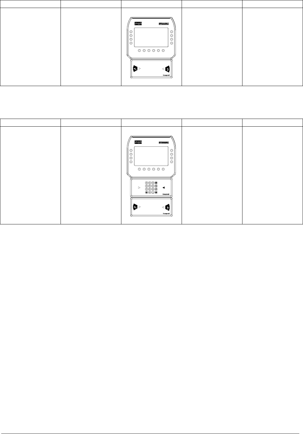
Interactive Terminals
Interactive TerminalsInteractive Terminals
Interactive Terminals
Code Grouping Horizontal Vertical Notes
TK-D27
1 x RTU-C02
1 x RTU-B07
1 x RTU-S03
NO
Weight=1.25Kg
Power=6W
Current=440mA
Interactive Terminals with Keyboards
Interactive Terminals with KeyboardsInteractive Terminals with Keyboards
Interactive Terminals with Keyboards
Code Grouping Horizontal Vertical Notes
TK_T27
1 x RTU-C02
1 x RTU-T01
1 x RTU-B07
1 x RTU-S03
1 x RTU-S01 NO
Weight=1.65Kg
Power=6.4W
Current=470mA
Attaching the Modules to the Wall Page 21
Attaching the Modules to the Wall
Attaching the Modules to the WallAttaching the Modules to the Wall
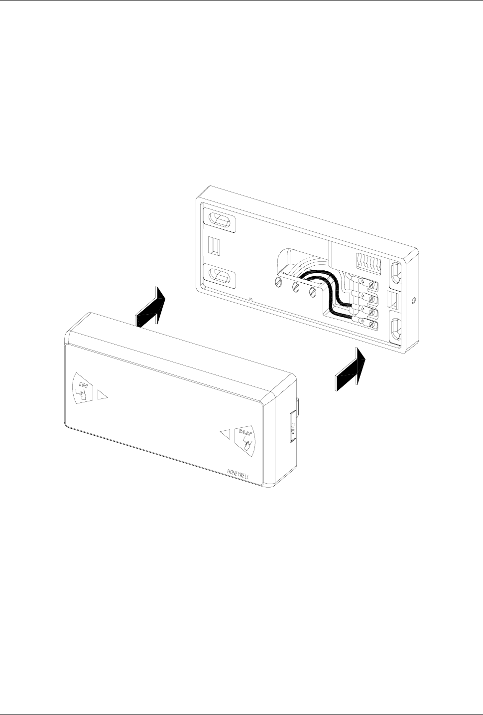
Attaching the Modules to the Wall
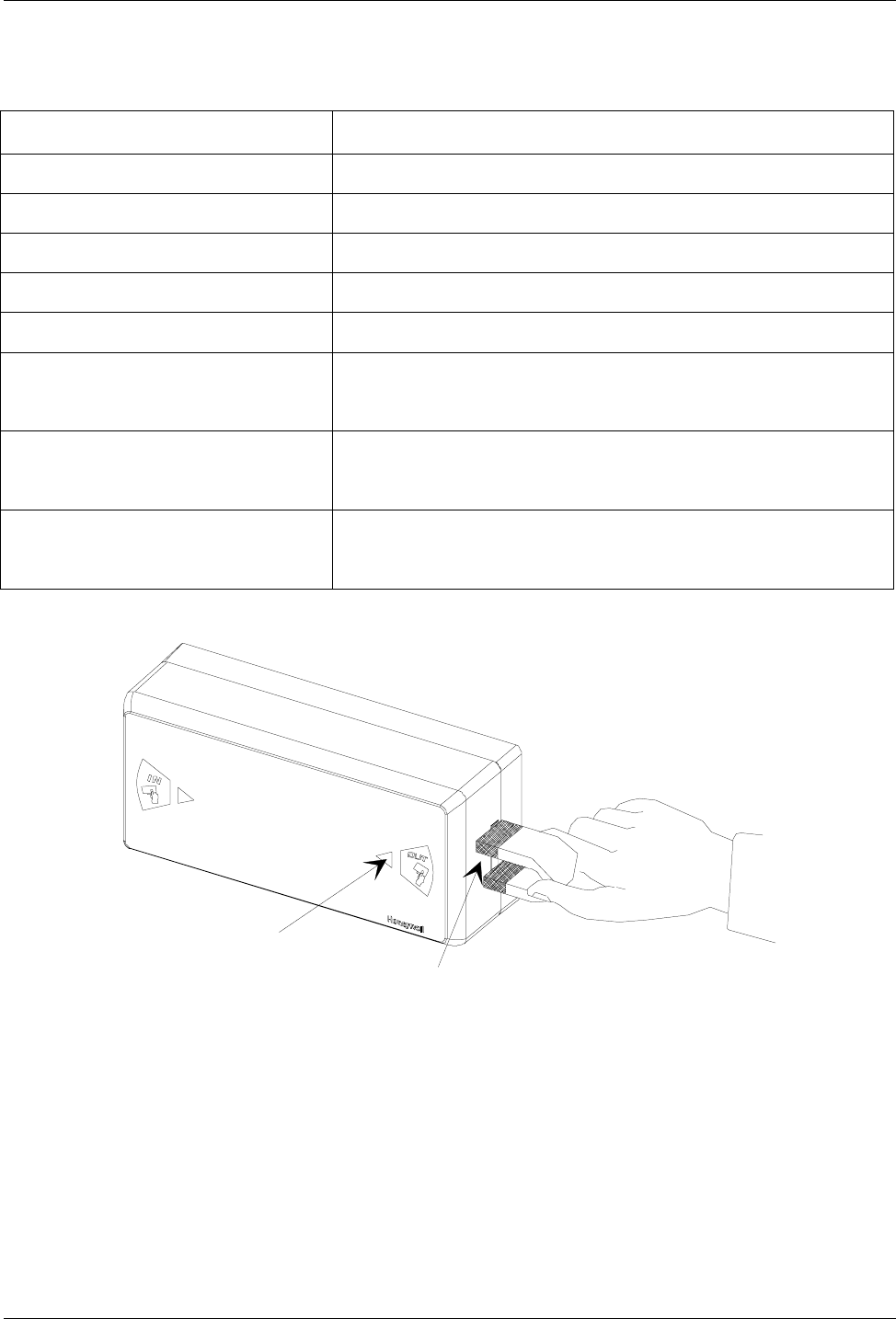
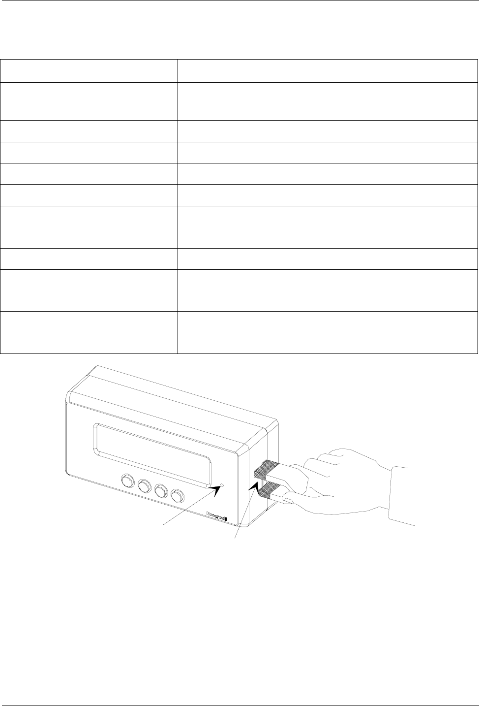
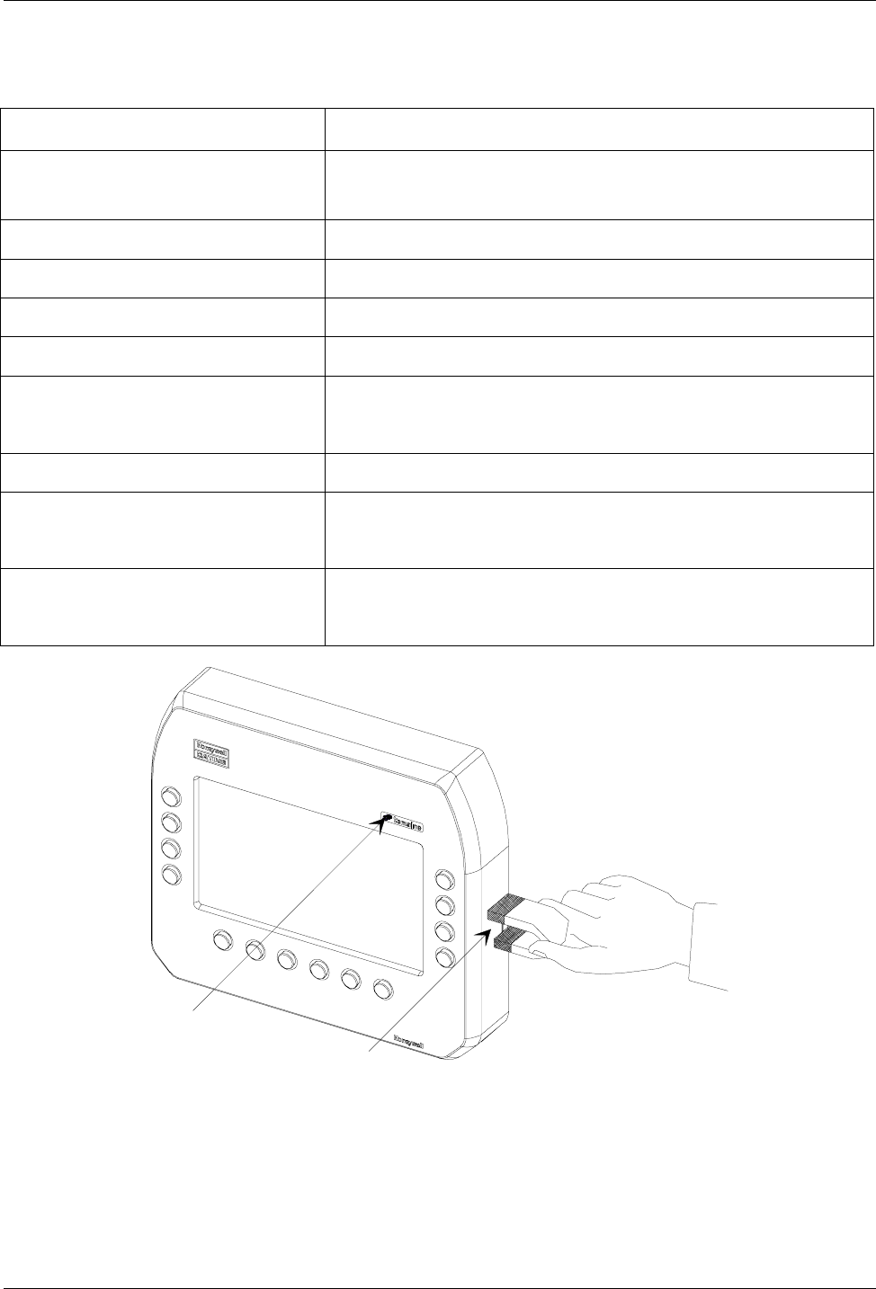
All tEmaline modules are equipped with a simple attachment
mechanism; the module clicks into position without the need for tools.
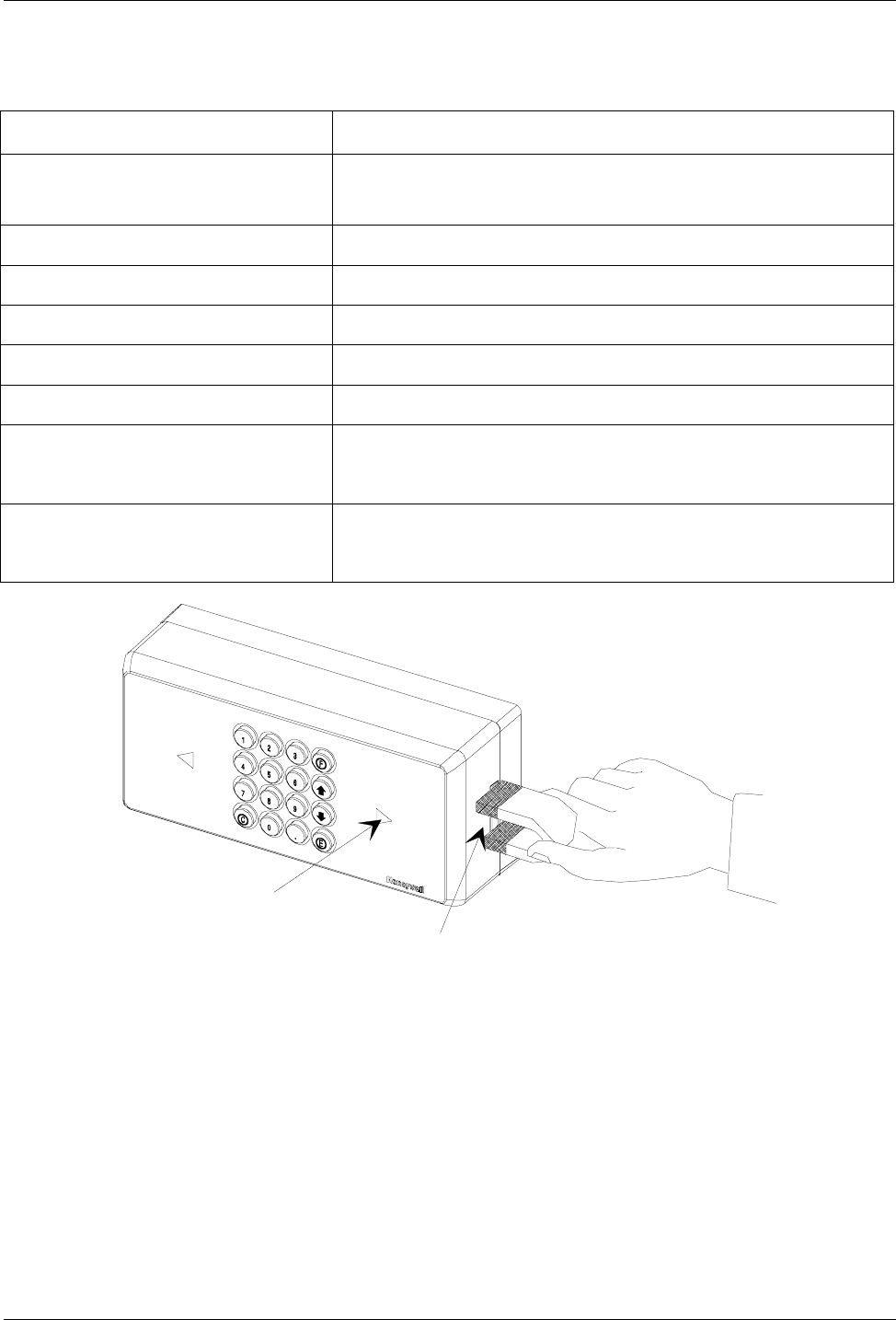
To attach the module to the frame, follow these steps:
1. Check that the fitting at the back of the RTU modules is positioned
correctly.
2. Attach each RTU module to the wall-mout frame as illustrated in
Figure 11.
Figure 11: Attaching the module to the wall-mount frame
Applying the Entry/Exit Labels Page 22
Applying the Entry/Exit Labels
Applying the Entry/Exit LabelsApplying the Entry/Exit Labels
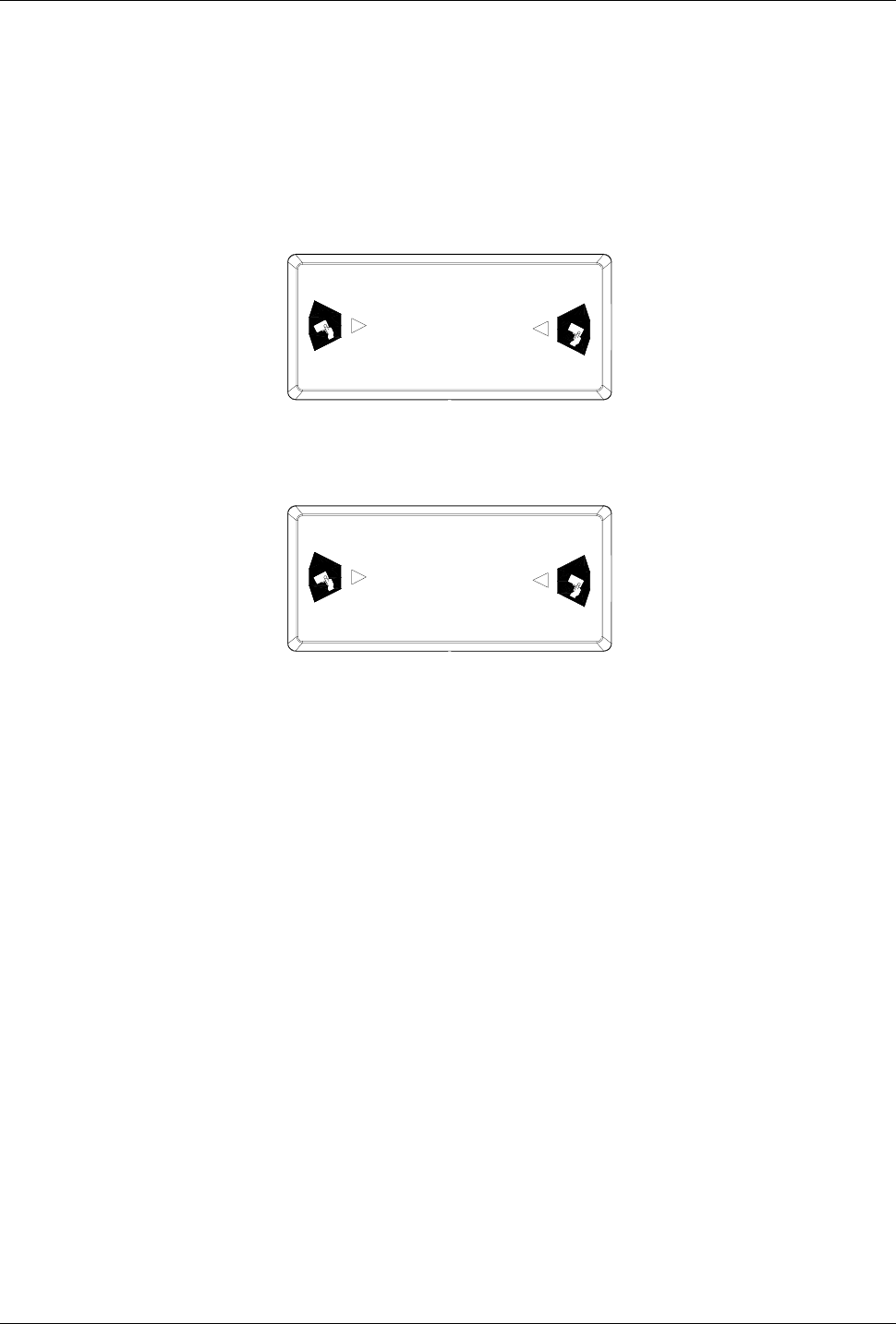
Applying the Entry/Exit Labels
Apply the two entry/exit labels to the magnetic reader according to
the pre-configured transit direction. Make sure that you place the
labels in the appropriate hollows (see details in Figure 12 and Figure
13).
IN
OUT
EXIT ENTRY
Figure 12: Entry/exit labels
OUT
IN
ENTRY EXIT
Figure 13: Entry/exit labels
Identification via Bar Code Page 23
Identification via Bar Code
Identification via Bar CodeIdentification via Bar Code
Identification via Bar Code
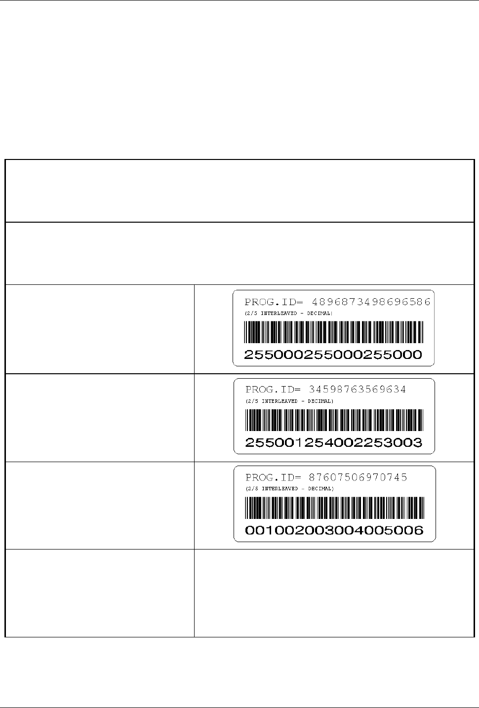
The components enclosed in the packaging include a bar code label.
The person responsible for installing the terminal must apply this label
to the corresponding identification form, and indicate the location of
the terminal in the appropriate box (see example in Table 3).
Description of location
Office entrance area, first floor - staircase E
Description of TemaServer
Panel 2 entrance area, first floor – staircase E
RTU
C01
RTU
T01
RTU
B07
RTU
-
Table 3: Example of completed identification form

Summary of Modular Devices Page 24
TECHNICAL DATA
Summary of Modular Devices
Summary of Modular DevicesSummary of Modular Devices
Summary of Modular Devices
This section contains technical data regarding the modular devices:
• RTU-B07 (Reader module for HID proxy cards)
• RTU-C01 (Alphanumeric LCD module)
• RTU-C02 (Graphic LCD module)
• RTU-T01 (Numeric keyboard module)
RTU-B07 (Proxy Reader for HID Cards) Page 25
RTU-B07
RTU-B07 RTU-B07
RTU-B07 (Proxy Reader for HID Cards)
for HID Cards)for HID Cards)
for HID Cards)
Code 1520145
Parameter
ParameterParameter
Parameter Value
ValueValue
Value
DC power supply 12VDC±15% 60mA
Weight 0.30 Kg
Dimensions 72 x 160 x 52 mm
IP Protection Rating IP55
Operating temperature 0-50 °C
Proxy receiver For HID cards
Double-antenna receiver (bidirectional)
LONWORKS® connection Unshielded twisted pair cable
(transceiver FTT10A, 78Kbps
Signaling 2 LED tricolor (green/red/yellow)
1 buzzer
Service Pin
Service LED
RTU-C01 (Alphanumeric LCD Module) Page 26
RTU-C01
RTU-C01 RTU-C01
RTU-C01 (Alphanumeric LCD Module)
Alphanumeric LCD Module)Alphanumeric LCD Module)
Alphanumeric LCD Module)
Code 1500105
Parameter
ParameterParameter
Parameter Value
ValueValue
Value
DC power supply 12VDC±15% 140mA (nominal)
70mA (backlight off)
Weight 0.30 Kg
Dimensions 72 x 160 x 52 mm
IP Protection Rating IP55
Operating temperature 0-50 °C
Display Alphanumeric LCD with backlight
2 rows of 16 characters format
Keyboard 4 keys with symbols
LONWORKS® connection Unshielded twisted pair cable
(transceiver FTT10A, 78Kbps
Signaling 1 LED yellow
1 buzzer
Service LED
Service Pin
RTU-C02 (Graphic LCD Module) Page 27
RTU-C02
RTU-C02 RTU-C02
RTU-C02 (Graphic LCD Module)
Graphic LCD Module)Graphic LCD Module)
Graphic LCD Module)
Code 1500101
Parameter
ParameterParameter
Parameter Value
ValueValue
Value
DC power supply 12VDC±15% 380mA (nominal),
140mA (backlight off)
Weight 0.65 Kg
Dimensions 166 x 190 x 52 mm
IP Protection Rating IP55
Operating temperature 0-50 °C
Display Graphic LCD with backlight
240 x 128 pixels format
Keyboard 14 function keys
LONWORKS® connection Unshielded twisted pair cable
(transceiver FTT10A, 78Kbps
Signaling 1 LED yellow
1 buzzer
Service LED
Service Pin
RTU-T01 (Numeric Keyboard Module) Page 28
RTU-T01
RTU-T01 RTU-T01
RTU-T01 (Numeric Keyboard Module)
))
)
Code 1500104
Parameter
ParameterParameter
Parameter Value
ValueValue
Value
DC power supply 12VDC±15%
30mA (nominal), 50mA (max)
Weight 0.25 Kg
Dimensions 72 x 160 x 52 mm
IP Protection Rating IP55
Operating temperature 0-50 °C
Keyboard 16 keys with symbols
LONWORKS® connection Unshielded twisted pair cable
(transceiver FTT10A, 78Kbps
Signaling 2 LED bicolor (red/green/yellow)
1 buzzer
Service LED
Service Pin

Optional Parts Page 29
Optional Parts
Optional PartsOptional Parts
Optional Parts
Unlocking tool code 3900695AB

Optional Parts Page 30
This page is intentionally left blank

Optional Parts Page 31
This page is intentionally left blank
This page is intentionally left blank

gçìÑëçÑìX>áììèXMMñññLìÑåÄãàçÑLÇéå