Ademco RTU-B12 RTU-B12 User Manual Tema1 0 TKMOD IM 1 2 US
Honeywell International Inc RTU-B12 Tema1 0 TKMOD IM 1 2 US
UserManual.wiki
>
Ademco
>
RTU B12 User Manual
manual
Navigation menu
Upload a User Manual
Namespaces
Wiki Guide
HTML
PDF
Info
Views
User Manual
Discussion / Help
Navigation
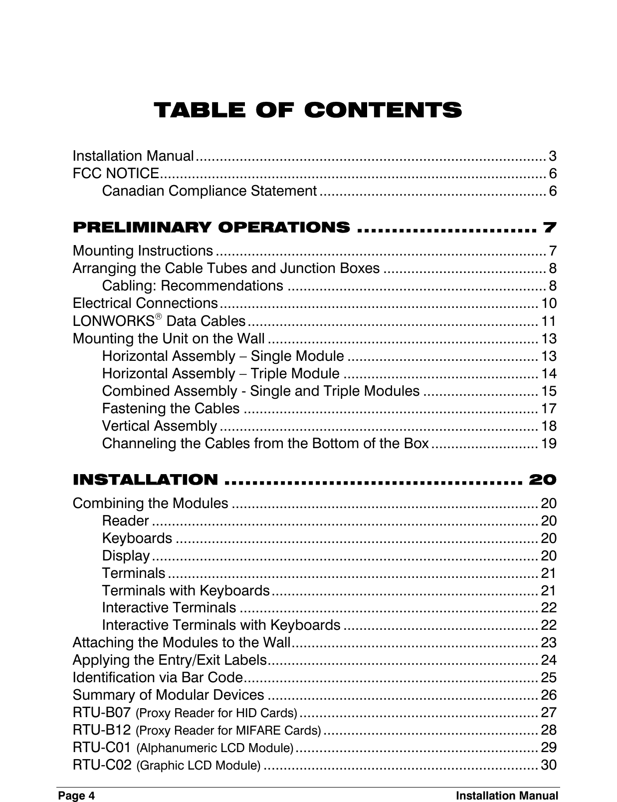
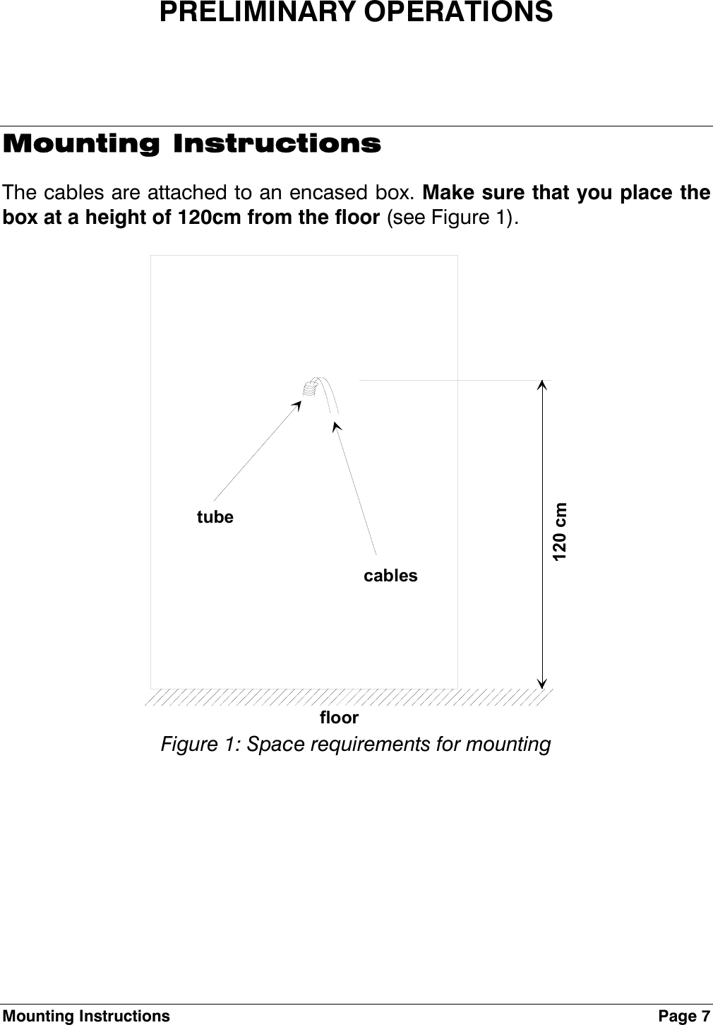
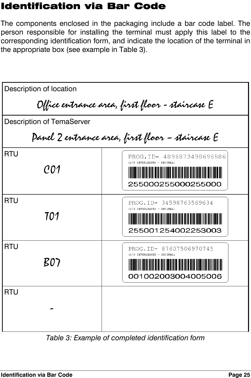
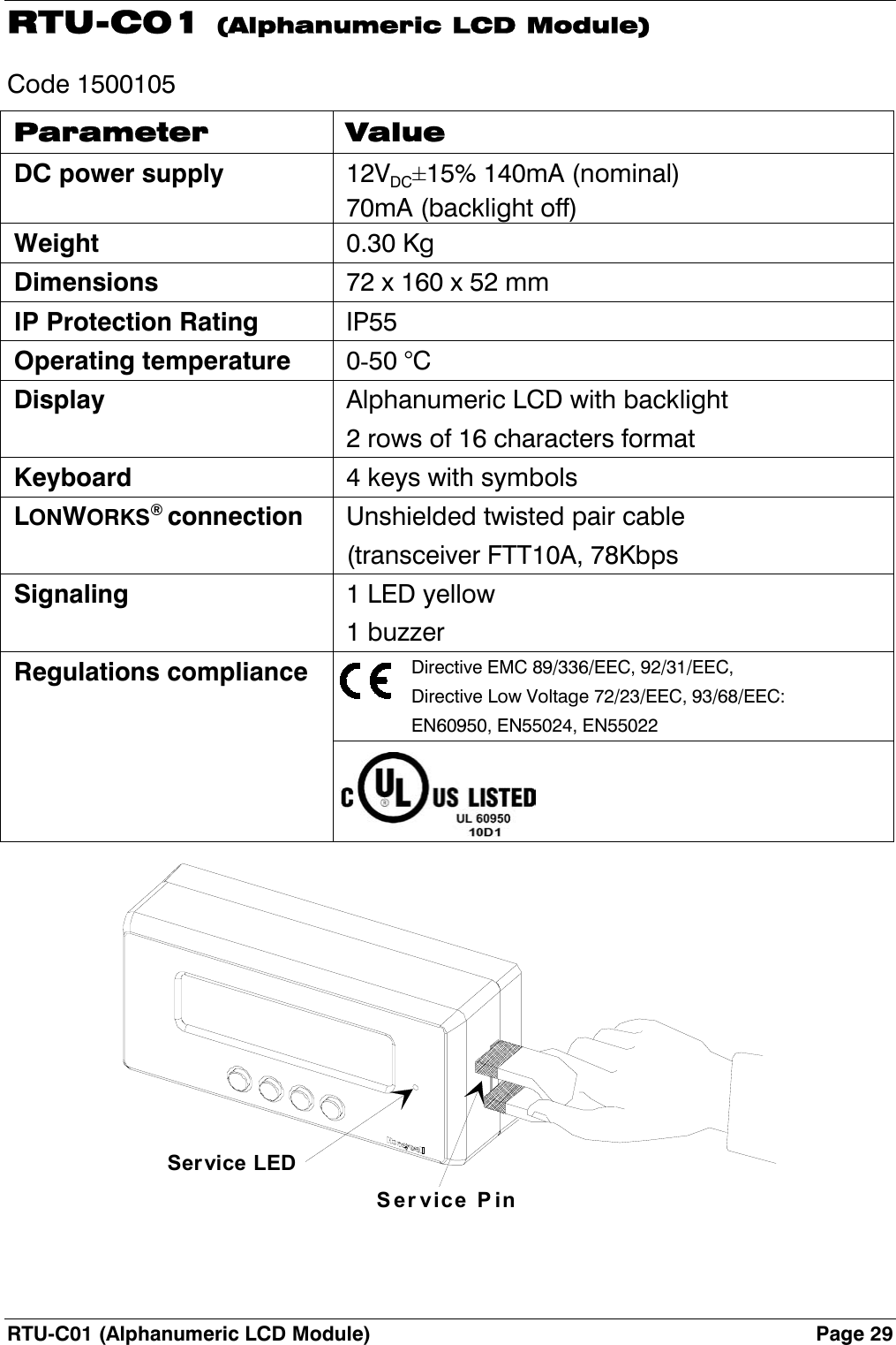
![Page 10 Electrical Connections Electrical Connections The RTU is powered at low voltage (12VDC 120mA) by a battery-operated power supply module (RTU-Qxx). When determining the correct size for power cables, refer to the table below. Type of cable Lengt h (m) in r elat ion t o effect ive loadAWG mm2 ohm/Km 100 [mA] 200 [mA] 500 [mA] 1 [A] 2 [A] 5 [A]12 3,3 5,7 1754 877 351 175 88 3514 2 8,8 1136 568 227 114 57 2316 1,3 14 714 357 143 71 36 1418 0,9 21 476 238 95 48 24 1020 0,6 34 294 147 59 29 15 622 0,35 52 192 96 38 19 10 424 0,2 85 118 59 24 12 6 2](https://usermanual.wiki/Ademco/RTU-B12/User-Guide-308510-Page-8.png)
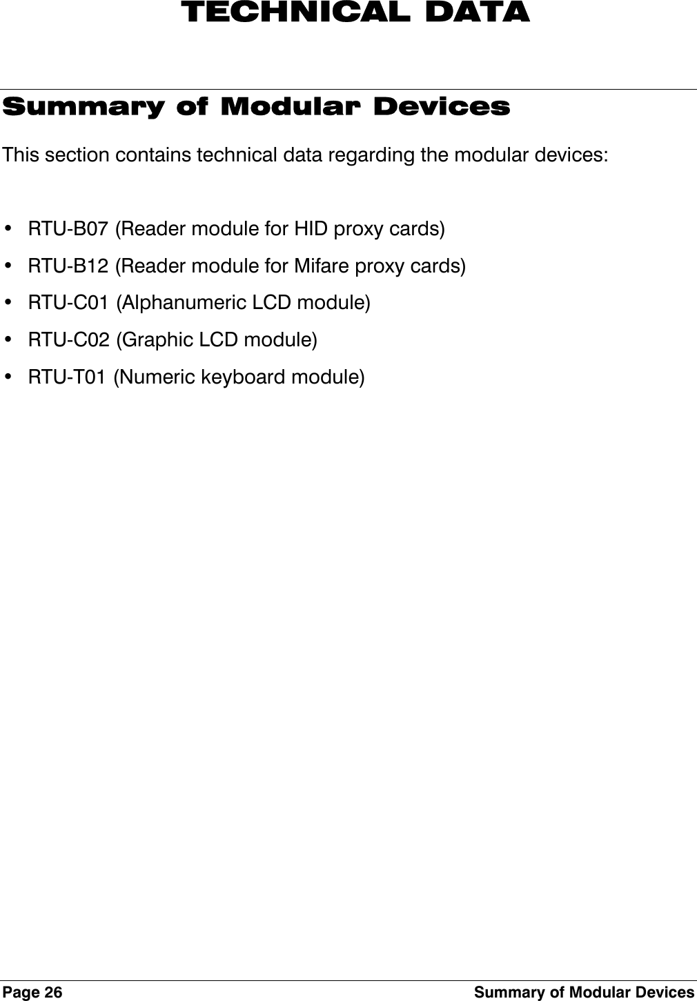
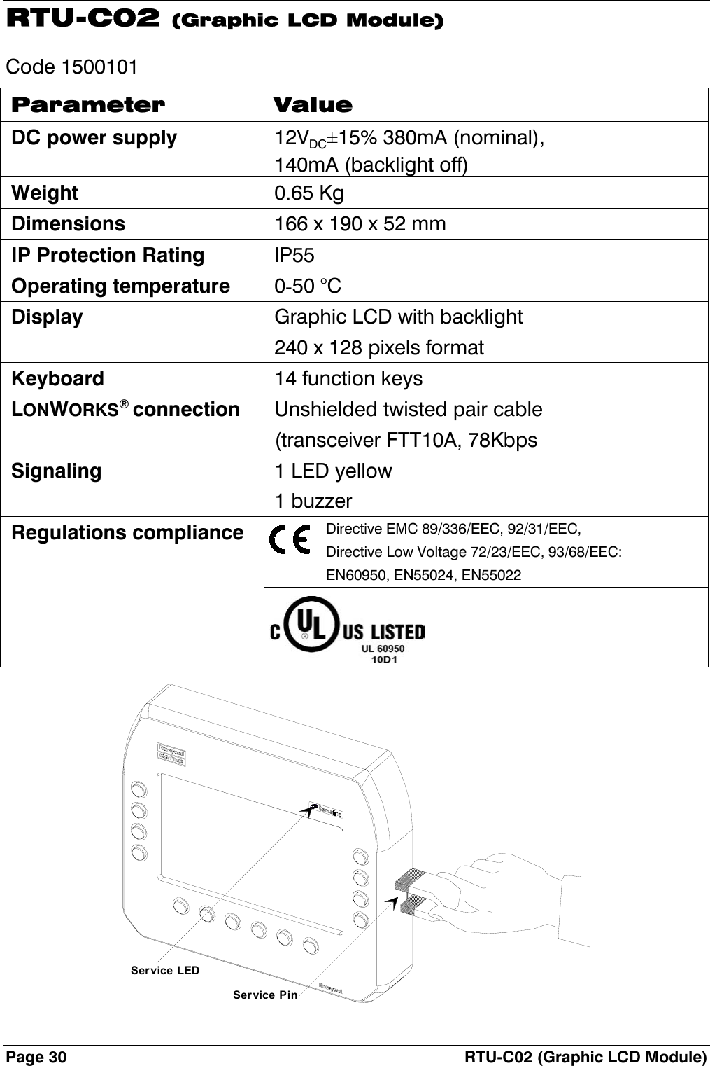
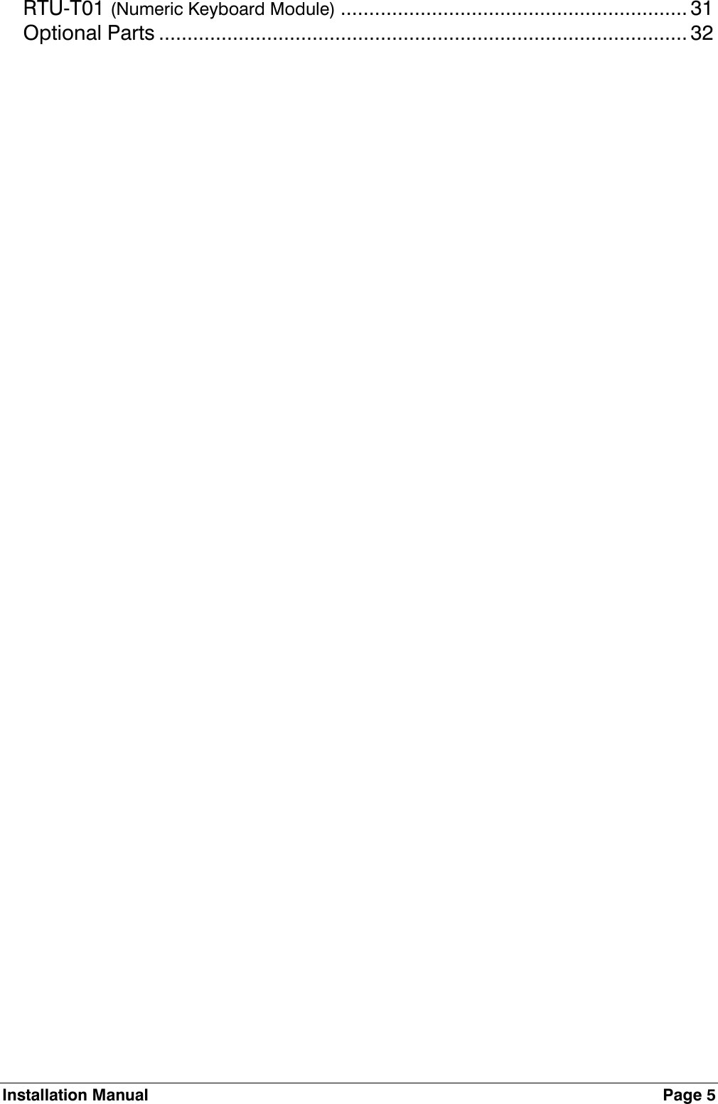
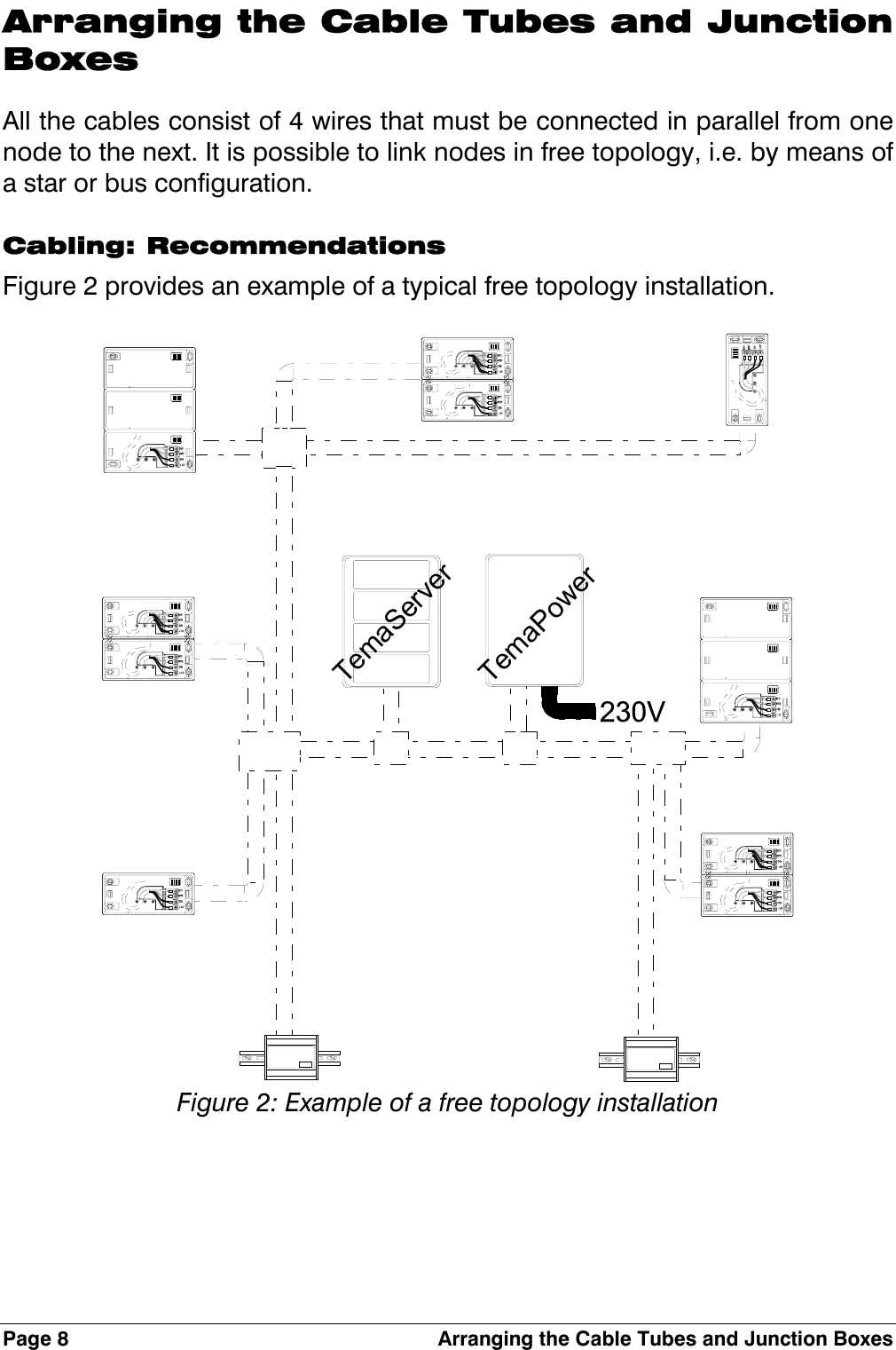
![LONWORKS( Data Cables Page 11 LONWORKS Data Cables • The LONWORKS1 data cable must be twisted pair • In a free topology configuration, the sum total of the sections must not exceed 500m • In a bus configuration, the sum total of the sections must not exceed 2700m • In a free topology configuration, activate the 50ohm terminator by placing the appropriate jumper on the FTT10A plug-in of the CTU-PLG06 board inside the TemaServer • In a bus configuration, place two terminators (with resistance values of 100ohm 1% ½W) at each end of the bus • Check that the length of the LONWORKS data cable corresponds to the norms indicated in Table 1. Type of cable Length [m] in relation to cable capacity AWG mm2 Ohm/Km 50nF/Km 100nF/Km 200nF/Km 500nF/Km 1uF/Km 12 3,3 5,7 2676 1892 1338 846 598 14 2 8,8 2153 1523 1077 681 482 16 1,3 14 1707 1207 854 540 382 18 0,9 21 1394 986 697 441 312 20 0,6 34 1096 775 548 346 245 22 0,35 52 886 626 443 280 198 24 0,2 85 693 490 346 219 155 Table 1: Length/capacity of LONWORKS data cables (m) 1 LONWORKS® is a trademark of Echelon Corporation](https://usermanual.wiki/Ademco/RTU-B12/User-Guide-308510-Page-9.png)
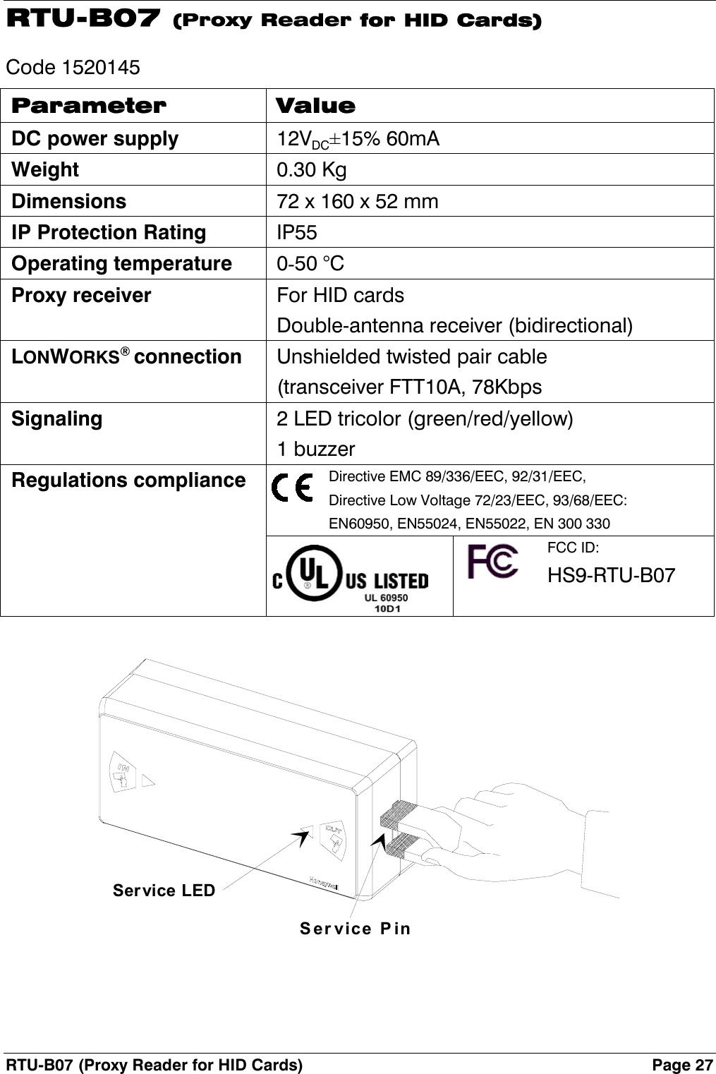
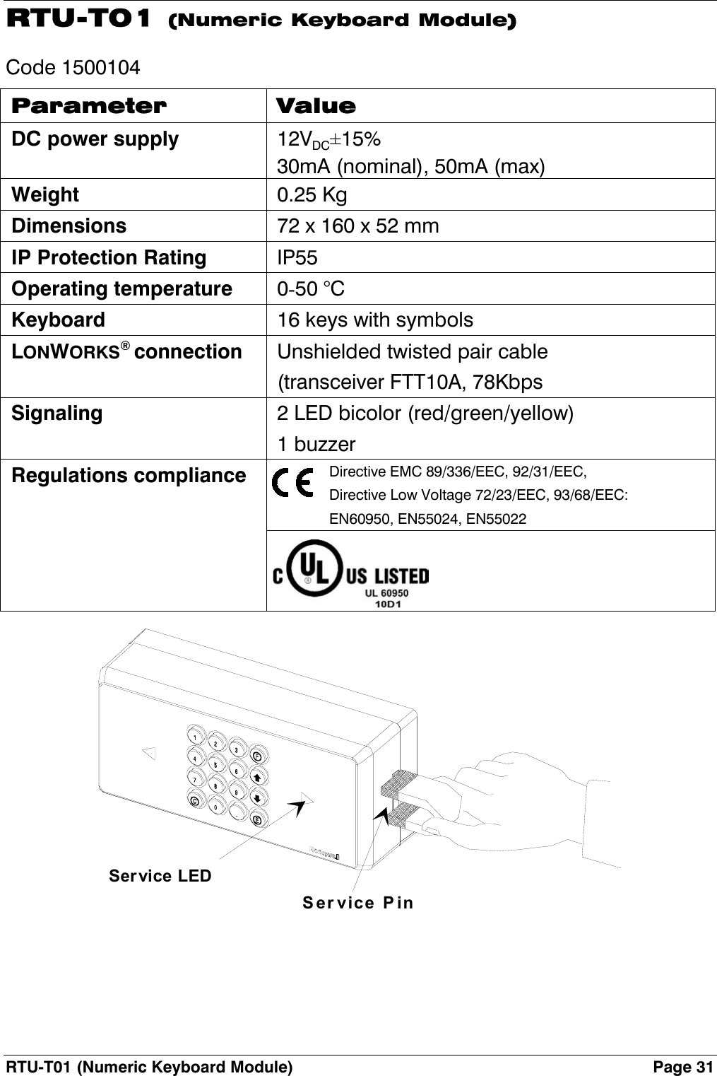
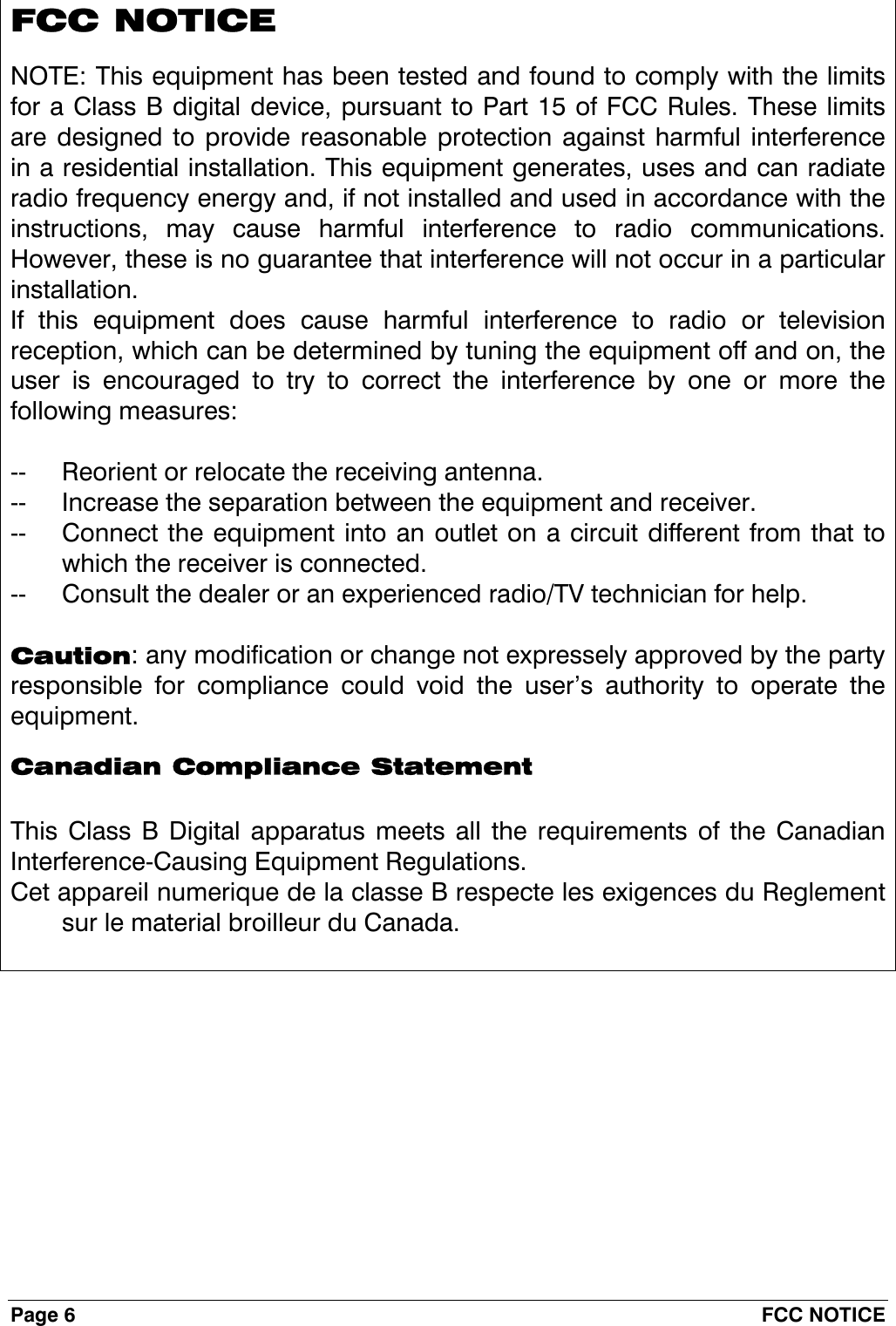
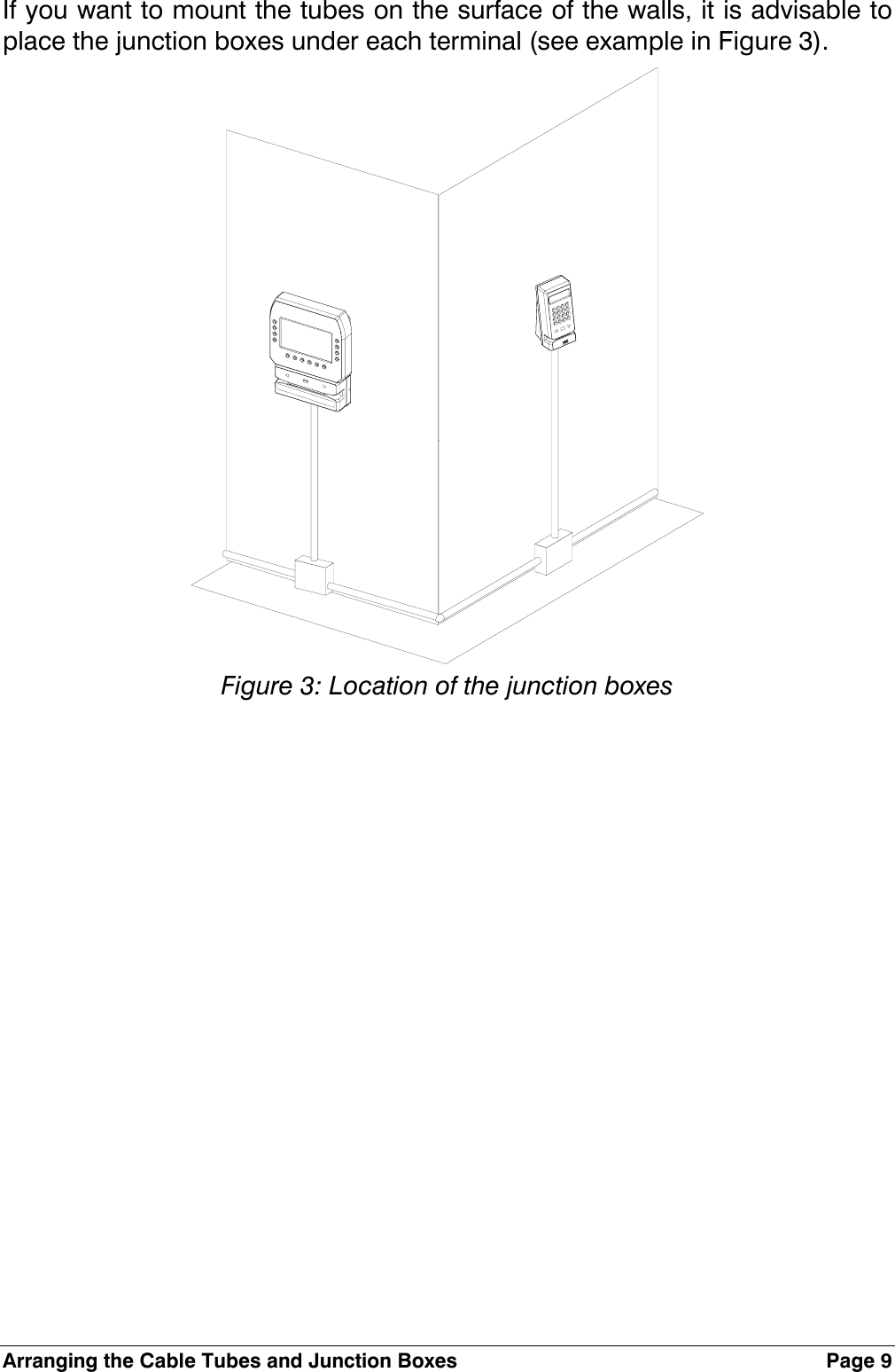
![Page 12 LONWORKS( Data Cables • The FTT10A Echelon v1.2 User Guide recommends the cables indicated in Table 2. Manufacturer and model AWG Connection to bus -maximum total length [m] Connection in free topology –maximum node-node length max. [m] Belden 85102 16 2700 500 Belden 8471 16 2700 400 Level IV (twisted pair, typically solid and unshielded) 22 1400 400 JY (St) 2x2x0.8 (4-wire helical twist, solid shielded) 20 900 320 Table 2: Recommended LONWORKS cables](https://usermanual.wiki/Ademco/RTU-B12/User-Guide-308510-Page-10.png)