Ademco RTU-K03 Temakey Compact Terminal User Manual Tema1 0 TKC03 IM 1 0 US
Honeywell International Inc Temakey Compact Terminal Tema1 0 TKC03 IM 1 0 US
Ademco >
manual

TK C03
TK C03TK C03
TK C03
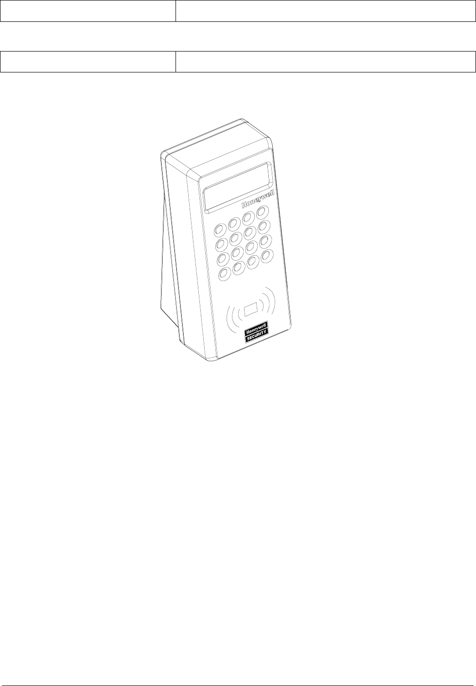
Compact Terminal
Compact TerminalCompact Terminal
Compact Terminal
Installation Manual
Installation ManualInstallation Manual
Installation Manual

TK C03
TK C03TK C03
TK C03
TABLE OF CONTENTS
TABLE OF CONTENTSTABLE OF CONTENTS
TABLE OF CONTENTS
FCC NOTICE............................................................................. 4
Canadian Compliance Statement .......................................... 4
PRELIMINARY OPERATIONS
PRELIMINARY OPERATIONSPRELIMINARY OPERATIONS
PRELIMINARY OPERATIONS ........................
................................................
........................5
55
5
Mounting Instructions .............................................................. 5
Electrical Connections .............................................................. 6
LONWORKS Data Cables......................................................... 7
Attaching the Terminal Support Plate......................................... 8
Channelling the Cables from the Bottom of the Box................ 9
INSTALLATION
INSTALLATIONINSTALLATION
INSTALLATION ................................
................................................................
.........................................
..................
.........10
1010
10
Connecting the Cables ............................................................ 10
Assembling the Terminal Closure Guide..................................... 13
Closing the Terminal (wall-mounted assembly)...................... 14
Closing the Terminal (Turnstile-mounted assembly)............... 16
ACTIVATION
ACTIVATIONACTIVATION
ACTIVATION ................................
................................................................
............................................
........................
............17
1717
17
Identification via the Service Pin............................................... 17
Identification via Bar Code ....................................................... 18
TECHNICAL SPECIFICATIONS
TECHNICAL SPECIFICATIONSTECHNICAL SPECIFICATIONS
TECHNICAL SPECIFICATIONS ....................
........................................
....................19
1919
19
TemaKey TK C03 (RTU-K03 code 1500063BA) .......................... 19
Spare Parts..................................................................... 20
Optional Parts ................................................................. 20
Version: 1.0 US

Page 4 FCC NOTICE
FCC NOTICE
FCC NOTICEFCC NOTICE
FCC NOTICE
NOTE: This equipment has been tested and found to comply with the limits
for a Class B digital device, pursuant to Part 15 of FCC Rules. These limits
are designed to provide reasonable protection against harmful interference
in a residential installation. This equipment generates, uses and can radiate
radio frequency energy and, if not installed and used in accordance with the
instructions, may cause harmful interference to radio communications.
However, these is no guarantee that interference will not occur in a particular
installation.
If this equipment does cause harmful interference to radio or television
reception, which can be determined by tuning the equipment off and on, the
user is encouraged to try to correct the interference by one or more the
following measures:
-- Reorient or relocate the receiving antenna.
-- Increase the separation between the equipment and receiver.
-- Connect the equipment into an outlet on a circuit different from that to
which the receiver is connected.
-- Consult the dealer or an experienced radio/TV technician for help.
Canadian Compliance Statement
Canadian Compliance StatementCanadian Compliance Statement
Canadian Compliance Statement
This Class B Digital apparatus meets all the requirements of the Canadian
Interference-Causing Equipment Regulations.
Cet appareil numerique de la classe B respecte les exigences du Reglement
sur le material broilleur du Canada.
Mounting Instructions Page 5
PRELIMINARY OPERATIONS
Mounting Instructions
Mounting InstructionsMounting Instructions
Mounting Instructions
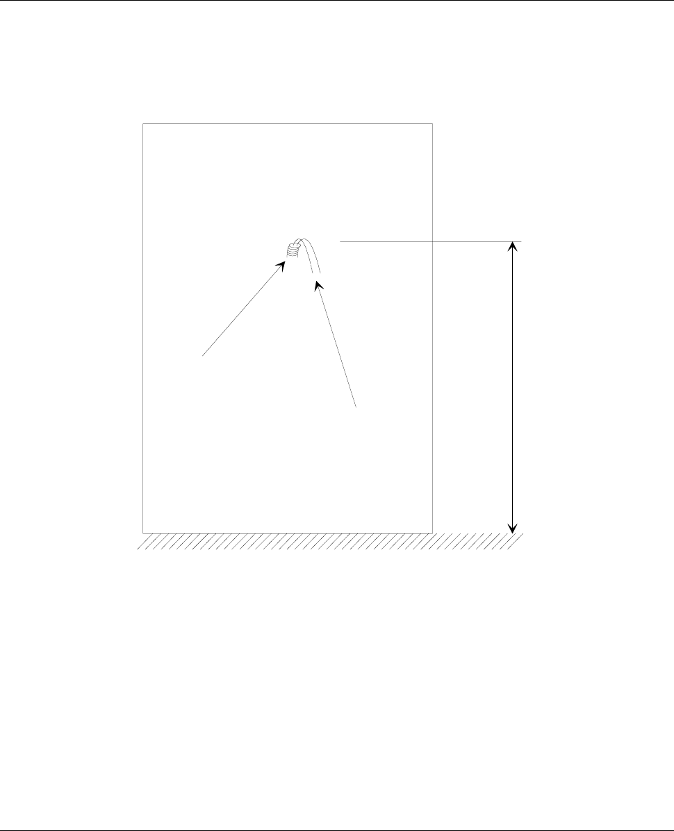
The cables are attached to an encased box. Make sure that you
place the box at a height of 120cm from the floor (see Figure 1).
tube
cables
120 cm
floo
r
Figure 1: Space requirements for mounting

Page 6 Electrical Connections
Electrical Connections
Electrical ConnectionsElectrical Connections
Electrical Connections
The RTU is powered at low voltage (12VDC 120mA) by a battery-
operated power supply module (RTU-Qxx). When determining the
correct size for power cables, refer to the table below.
Type of cable Length (m) in relation to effective load
AWG mm2 ohm/Km 100 [mA] 200 [mA] 500 [mA] 1 [A] 2 [A] 5 [A]
12 3,3 5,7 1754 87
7
351 175 88 35
14 2 8,8 1136 568 22
7
114 5
7
23
16 1,3 14 714 35
7
143713614
180,9214762389548241
0
20 0,6 34 294 14
7
59 29 15 6
22 0,35 52 19
2
96 38 19 1
0
4
24 0,2 85 118 59 24 1
2
62
LONWORKS( Data Cables Page 7
L
LL
LON
ONON
ONW
WW
WORKS
ORKSORKS
ORKS Data Cables
Data Cables Data Cables
Data Cables
• The LONWORKS 1 data cable must be twisted pair
• In a free topology configuration, the sum total of the sections must
not exceed 500m
• In a bus configuration, the sum total of the sections must not
exceed 2700m
• In a free topology configuration, activate the 50ohm terminator by
placing the appropriate jumper on the FTT10A plug-in of the CTU-
PLG06 board inside the TemaServer
• In a bus configuration, place two terminators (with resistance
values of 100ohm 1% ½W) at each end of the bus
• Check that the length of the LONWORKS data cable corresponds
to the norms indicated in Table 1.
Type of cable Length [m] in relation to cable capacity
AWG mm2 Ohm/Km 50nF/Km 100nF/Km 200nF/Km 500nF/Km 1uF/Km
12 3,3 5,7 2676 1892 1338 846 598
14 2 8,8 2153 1523 1077 681 482
16 1,3 14 1707 1207 854 540 382
18 0,9 21 1394 986 697 441 312
20 0,6 34 1096 775 548 346 245
22 0,35 52 886 626 443 280 198
24 0,2 85 693 490 346 219 155
Table 1: Length/capacity of LONWORKS data cables (m)
• The FTT10A Echelon v1.2 User Guide recommends the cables
indicated in Table 2.
Producer and model AWG Connection to bus -
maximum total length [m]
Connection in free topology –
maximum node-node length
max. [m]
Belden 85102 16 2700 500
Belden 8471 16 2700 400
Level IV (twisted pair,
typically solid and
unshielded)
22 1400 400
JY (St) 2x2x0.8 (4-wire
helical twist, solid
shielded)
20 900 320
Table 2: Recommended LONWORKS cables
1 LONWORKS® is a trademark of Echelon Corporation
Page 8 Attaching the Terminal Support Plate
Attaching the Terminal Support Plate
Attaching the Terminal Support PlateAttaching the Terminal Support Plate
Attaching the Terminal Support Plate
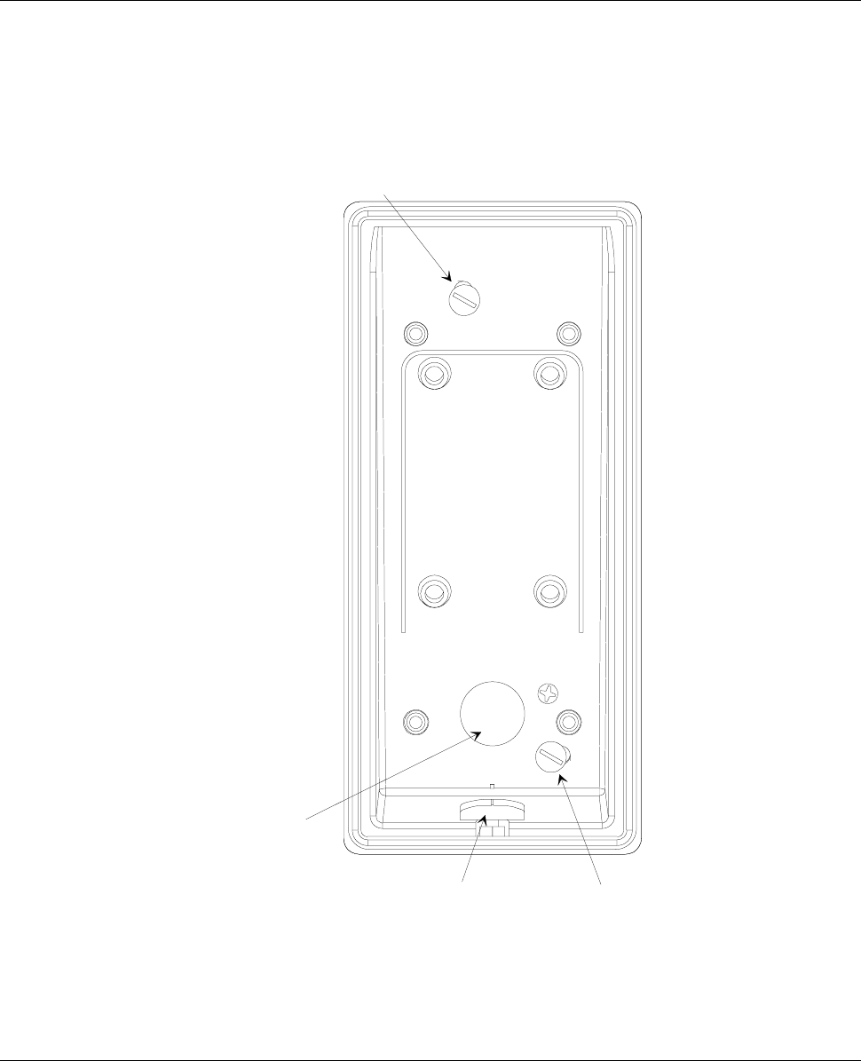
To attach the terminal support plate, follow these steps:
1. Drill two holes in the wall to accommodate the plastic anchors that
hold up the support plate (you must use M4 screws).
2. Make sure that the box attached to the wall is aligned with the
niche on the lower part of the support plate
3. Use a ∅ 4mm slotted screwdriver.
A
ncho
r
A
ncho
r
Cables
entrance
Figure 2: Attaching the support plate
Attaching the Terminal Support Plate Page 9
Channelling the Cables from the Bottom of the Box
Channelling the Cables from the Bottom of the BoxChannelling the Cables from the Bottom of the Box
Channelling the Cables from the Bottom of the Box
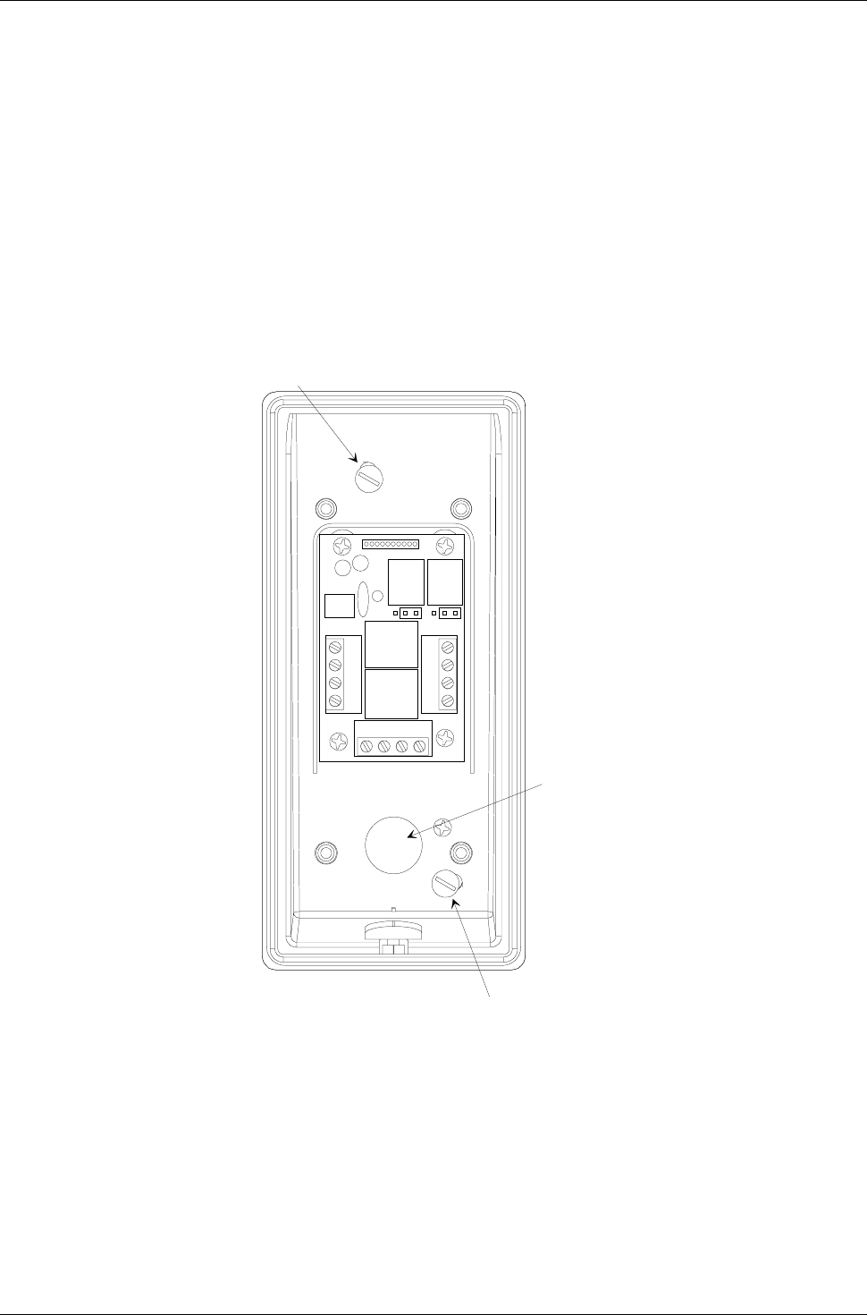
As an alternative, you can channel the cables so that they exit from
the bottom of the box (see Figure 3). This alternative procedure
consists of the following steps:
1. Drill a hole in the breakaway tab and apply a cable clamp with a
clutch for the cable tube.
2. Remove the cable clamps from the rear side and apply the stopper.
Anchor
Ancho
r
PG9 cable
clamp
Multi-pole
cable
(15 poles)
Figure 3: Channelling the cables from the bottom of the box
Page 10 Connecting the Cables
INSTALLATION
Connecting the Cables
Connecting the CablesConnecting the Cables
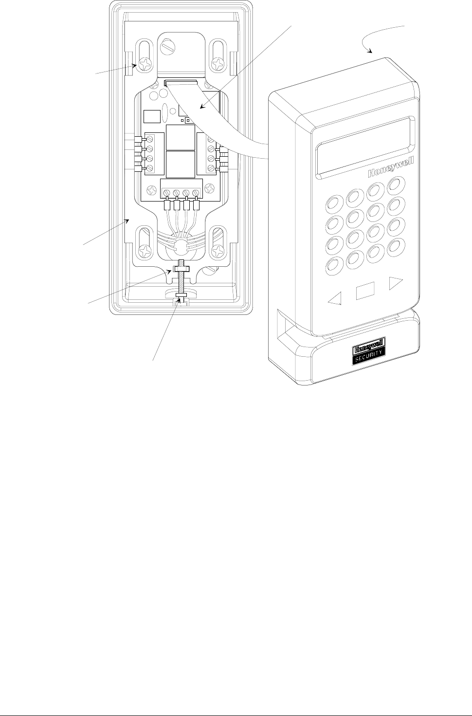
Connecting the Cables
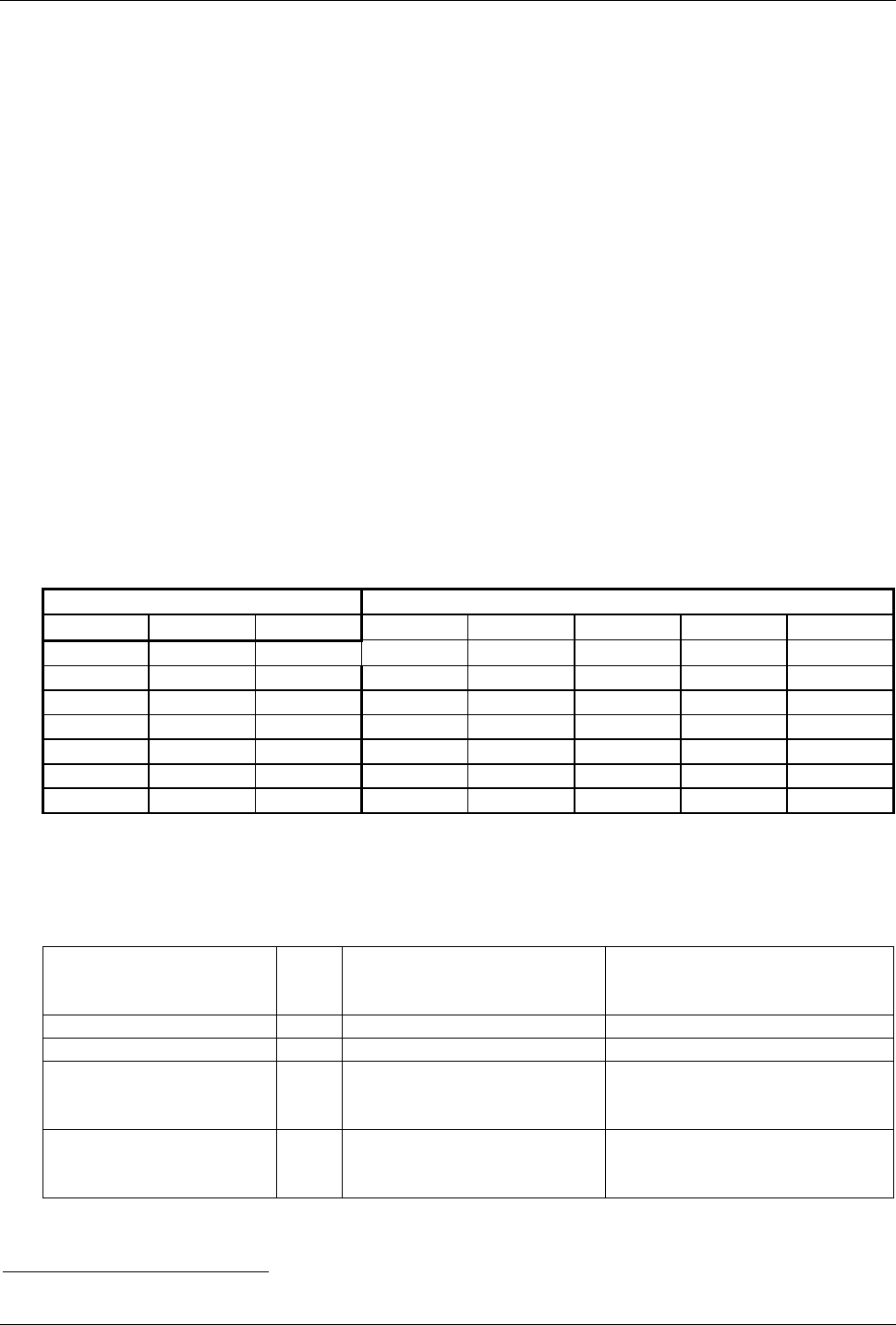
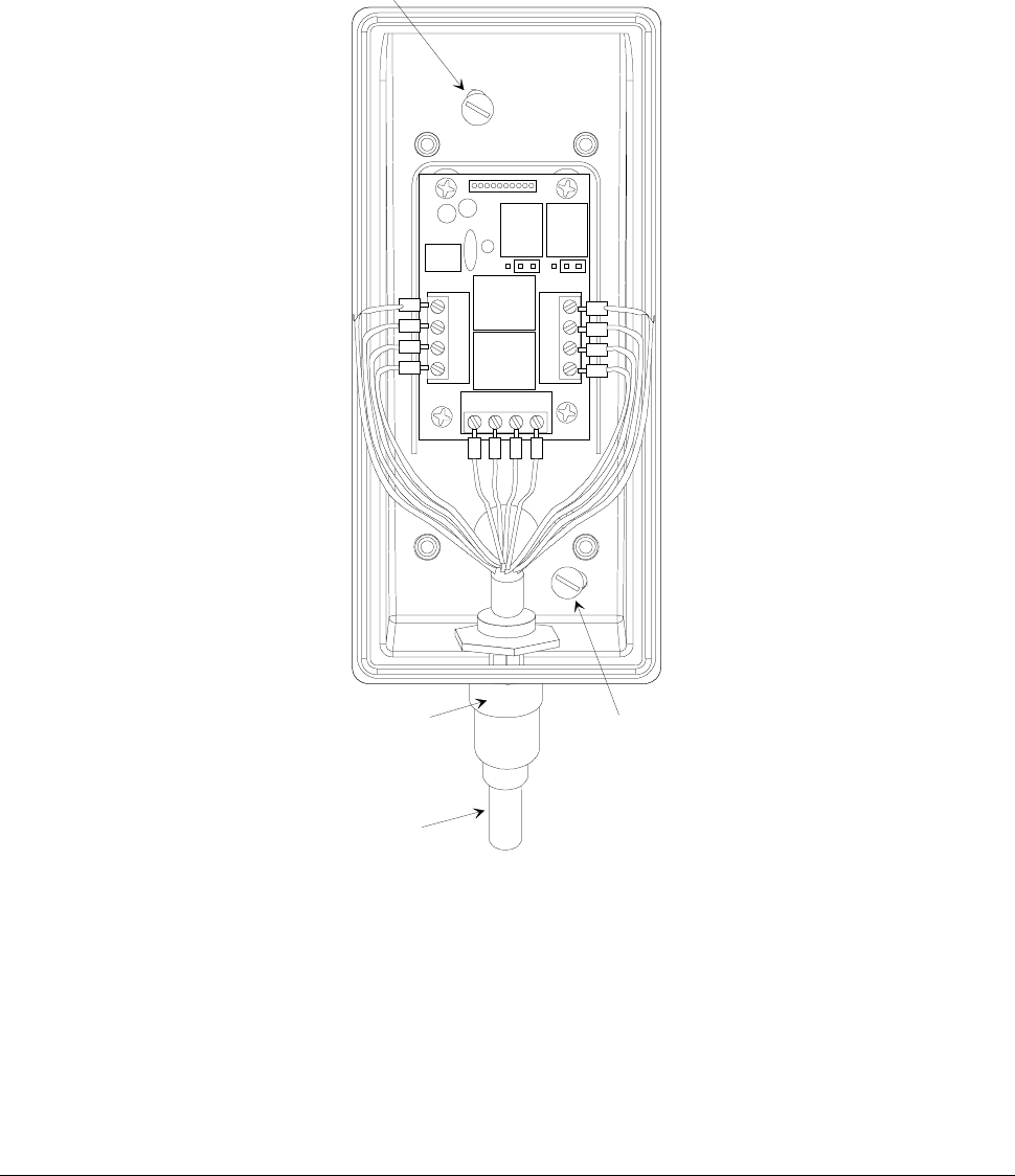
Insert and fasten the power, data and I/O cables in the connector
(see Figure 4 and Figure 5). If there is also a small grounding cable,
use a cable clamp to connect it to the screw supporting the card.
Anchor
Anchor
Breakaway tab
for cables exit
from bottom
Breakaway tab
for cables exit
from back
Figure 4: Connecting the cables (1)
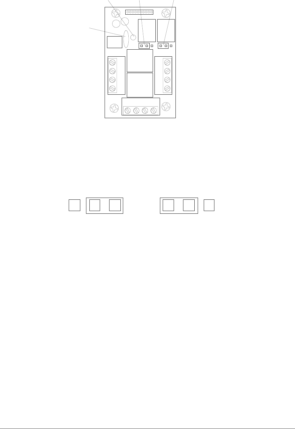
Connecting the Cables Page 11
relay 1 common
relay 1 NO/NC
relay 2 common
relay 2 NO/NC
input 1+
input 1-
input 2+
input 2-
+12V
ground
NET-A
NET-B
LED «on»
fuse
jumper
relay 1
jumper
relay 2
Figure 5: Connecting the cables (2)
You can define each relay as Normally Open (NO) or Normally Closed
(NC) by setting the jumpers as illustrated in Figure 6.
NO NC NO NC
normally closed (NC) normally open (NO)
Figure 6: Auxiliary connections
Page 12 Connecting the Cables
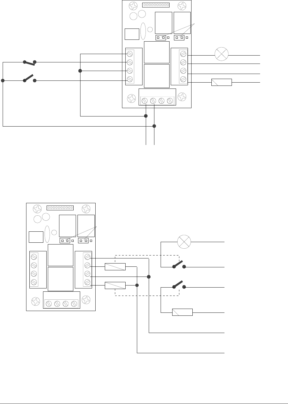
The typical connection for dry contacts in shown in Figure 7.
input 1+
input 1-
input 2+
input 2-
Normally closed (door)
Push Button Electrolock
Power supply
for lamp
Power supply
for lock
+12V Ground
Dry contact
Normally open (Exit)
Lamp (Gate busy)
N.O. position
Figure 7: Clean contacts connection example
When the output loads exceed the maximum ratings for the internal
relays, external relays must be used as shown in Figure 8.
N.O. position
Power supply
for lamp
Power supply
for lock
Lamp (Gate busy)
Electrolock
Power supply
for relays
Figure 8: External relays example
Assembling the Terminal Closure Guide Page 13
Assembling the Terminal Closure Guide
Assembling the Terminal Closure GuideAssembling the Terminal Closure Guide
Assembling the Terminal Closure Guide
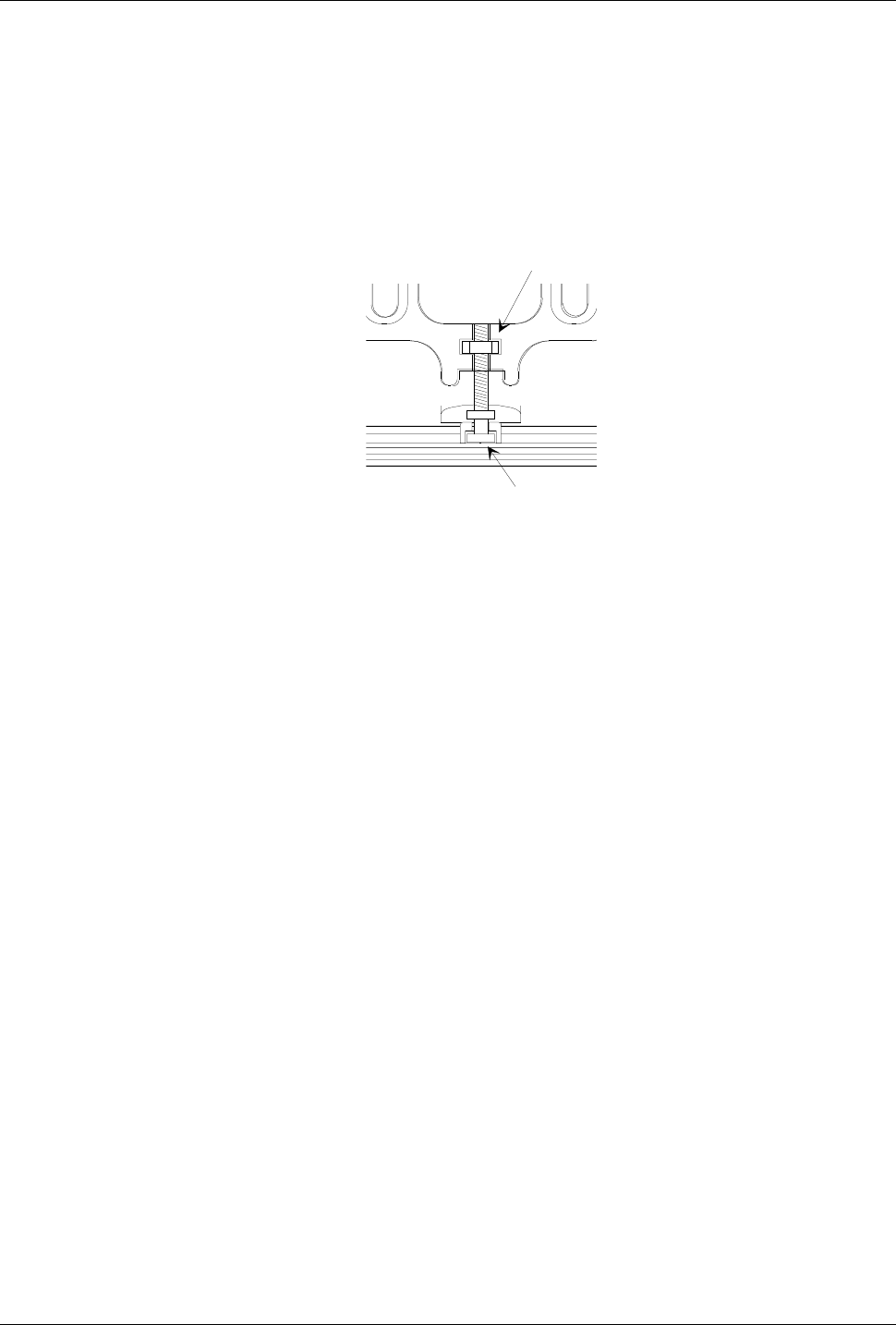
To assemble the terminal closure guide, follow these steps:
1. Use the 4 special screws to assemble and fasten the terminal
closure guide.
2. Insert the nut and the special screw in the corresponding niche on
the guide (see Figure 9).
nut
screw head
Figure 9: Mounting the terminal closure guide (1)
Make sure that the fitting is correctly positioned and then insert the
flat cable from the front casing in the connector (see Figure 10).
Page 14 Assembling the Terminal Closure Guide
flat cable
special
screws
closure
guide
nut
special star-shaped screw
O-ring
Figure 10: Mounting the terminal closure guide (2)
Closing the Terminal (wall-mounted assembly)
Closing the Terminal (wall-mounted assembly)Closing the Terminal (wall-mounted assembly)
Closing the Terminal (wall-mounted assembly)
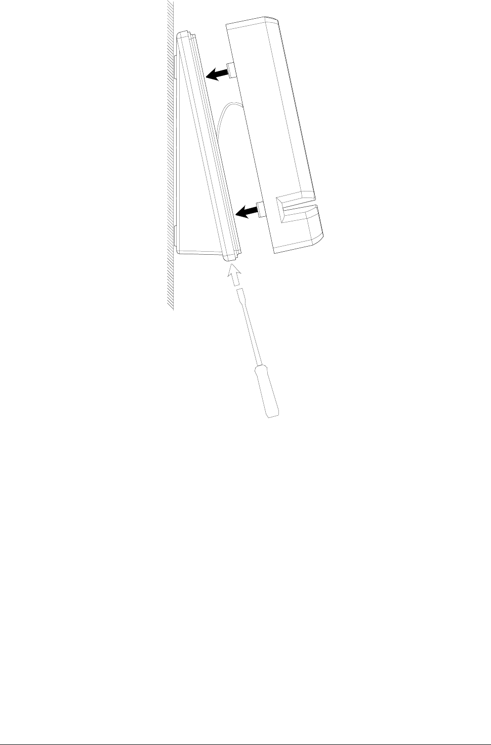
To close a wall-mounted terminal, follow these steps:
1. Unscrew the special closure screw by turning it in an anti-
clockwise direction so that the terminal closure remains fully open
(in the direction of the wedge).
2. Insert the upper shell as indicated in Figure 11.
3. Fasten the special closure screw by turning it in a clockwise
direction and pushing down on the shell so that the fitting is
completely secure.
4. Tighten the screw.
Assembling the Terminal Closure Guide Page 15
Figure 11: Closing the terminal (wall-mounted assembly)
Page 16 Assembling the Terminal Closure Guide
Closing the Terminal (Turnstile-mounted assembly)
Closing the Terminal (Turnstile-mounted assembly)Closing the Terminal (Turnstile-mounted assembly)
Closing the Terminal (Turnstile-mounted assembly)
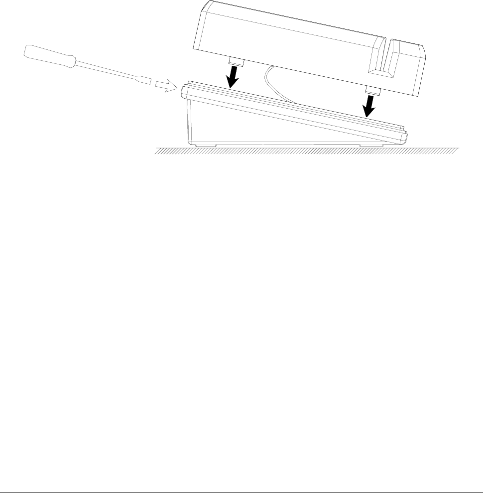
To close a anchor-mounted terminal, follow these steps:
1. Unscrew the special closure screw by turning it in an anti-
clockwise direction so that the terminal closure remains fully open
(in the direction of the wedge).
2. Insert the upper shell as indicated in Figure 12.
3. Fasten the special closure screw by turning it in a clockwise
direction and pushing down on the shell so that the fitting is
completely secure.
4. Tighten the screw.
Figure 12: Closing the terminal (anchor-mounted assembly)
Identification via the Service Pin Page 17
ACTIVATION
Identification via the Service Pin
Identification via the Service PinIdentification via the Service Pin
Identification via the Service Pin
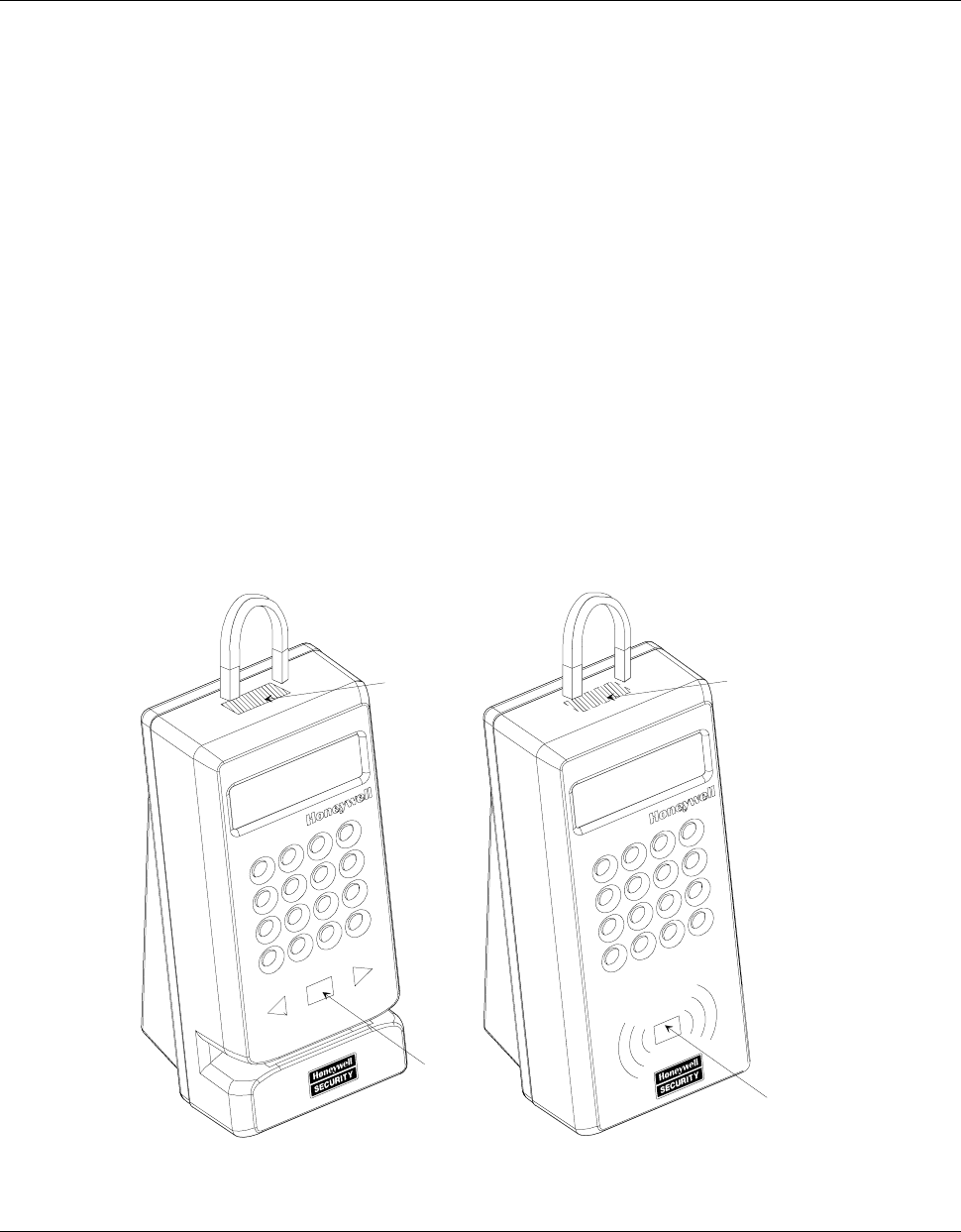
To identify the node, you can call the service pin by means of a relay-
reed located inside the unit (see Figure 13). This procedure consists
of the following steps:
1. Position a small magnet as illustrated in Figure 13 to call the
service pin. This signal is linked to the yellow central service LED,
which flashes throughout the node configuration procedure.
2. The TemaServer, in response to the service pin, sends a wink
command that makes yellow LED flash three times. This allows you
to verify that the communication to and from the TemaServer is
working.
3. Check that the service LED remains off after you have completed
this operation.
Magnet Magnet
SERVICE
LED
service pin
(reed)
service
LED
service pin
(reed)
Figure 13: Using a magnet to call the service pin
Page 18 Identification via Bar Code
Identification via Bar Code
Identification via Bar CodeIdentification via Bar Code
Identification via Bar Code
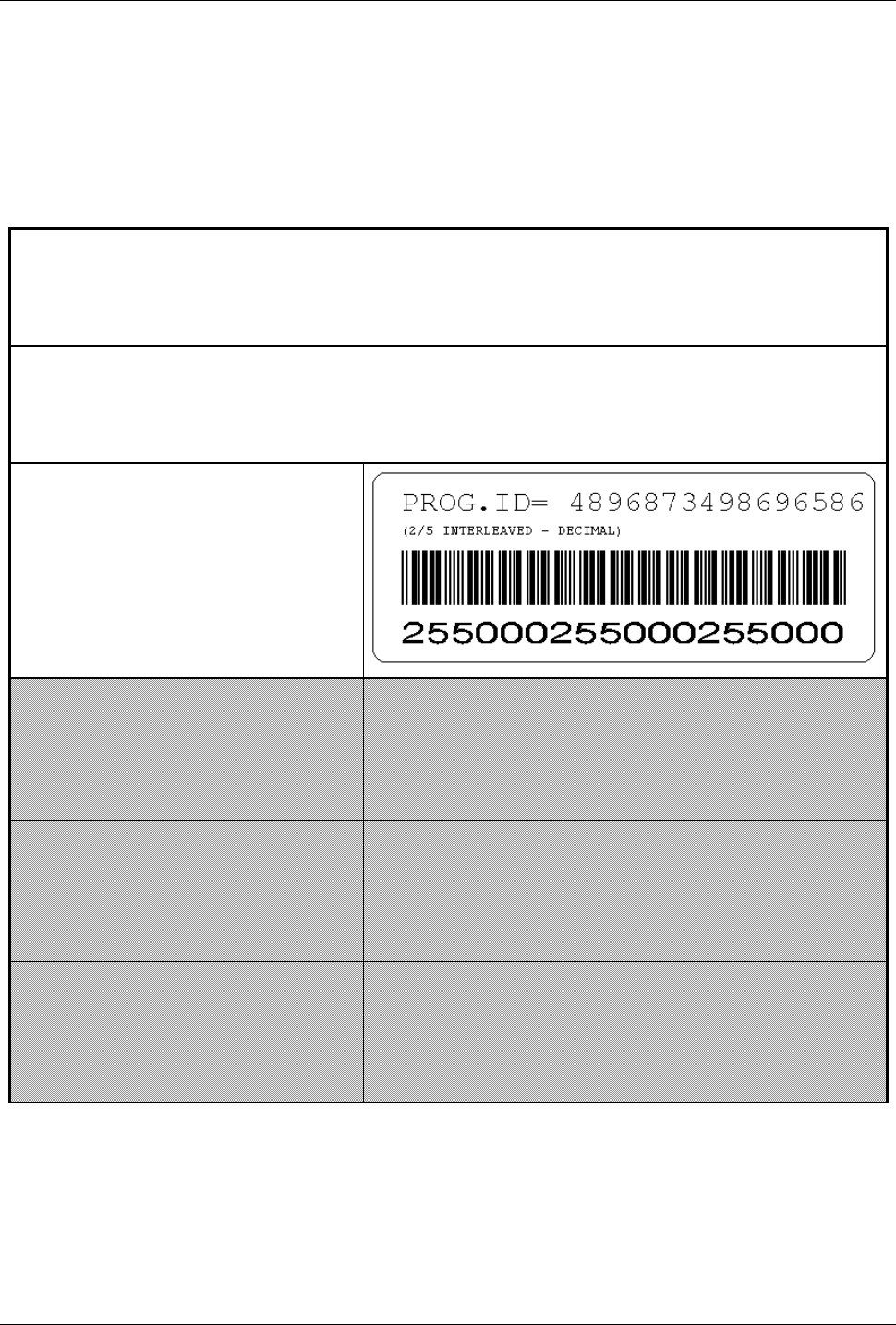
The components enclosed in the packaging include a bar code label.
The person responsible for installing the terminal must apply this label
to the corresponding identification form, and indicate the location of
the terminal in the appropriate box (see example in Table 3).
Description of location
Office entrance area, first floor - staircase E
Description of TemaServer
Panel 2 entrance area, first floor – staircase E
TKC02 (RTU-K02)
Table 3: Example of completed identification form

TemaKey TK C03 (RTU-K03 code 1500063BA) Page 19
TECHNICAL SPECIFICATIONS
TemaKey TK C03
TemaKey TK C03 TemaKey TK C03
TemaKey TK C03 (RTU-K03 code 1500063BA)
Parameter
ParameterParameter
Parameter Value
ValueValue
Value
DC power supply 12VDC±15% 130mA nominal (1.8W),
150mA max (2.1W)
Weight 0.4 kg
Size 72x160x75 mm
Protection level IP55
Environmental
temperature for
correct operation
0÷50 °C
Inputs Number of inputs: 2
Resistance: 2.2 Kohm
Logic level high:
>4.0 VDC (max. positive +18 VDC)
Logic level low:
<0.7 VDC (min. negative –0.5 VDC)
Relay outputs Number of outputs: 2
30VDC 1A
125VAC 200 mA
Proxy antenna 125KHz for HID cards
Read distance 0÷50mm
LONWORKS®2
connection
Unshielded twisted pair cable in free
topology (transceiver FTT10A, 78Kbps)
Regulations compliance Directive EMC 89/336/EEC, 92/31/EEC,
Directive Low Voltage 72/23/EEC, 93/68/EEC:
EN60950, EN55024, EN55022, EN 300 330
2 LONWORKS® is a trademark of Echelon Corporation
Page 20 TemaKey TK C03 (RTU-K03 code 1500063BA)
Spare Parts
Spare PartsSpare Parts
Spare Parts
Fuses F1 1A 250V delayed
Optional Parts
Optional PartsOptional Parts
Optional Parts
TORX screwdriver TX10 code 1500108AA

gçìÑëçÑìX>áììèXMMñññLìÑåÄãàçÑLÇéå