Ademco T8665C Wireless Thermostat User Manual A
Honeywell International Inc Wireless Thermostat A
Ademco >
users manual
HS9-T8665C
1
Test Report
DUT: Thermostat with RF Tranceiver
Model T8665C
Test Date: 13-July-2001
Manufacturer: Honeywell, Inc.
Home and Building Controls
1985 Douglas Drive
(763) 954-4972
Conducted by: Control Design & Testing, Inc.
6010 Red Fox Drive
Spotsylvania, VA 22553
(540) 582-2826
HS9-T8665C
2
CD&T FCC ID: HS9-T8665C
A. DEVICE UNDER TEST
The product submitted for test is a thermostat used to control heating and air
conditioning systems. The product incorporates a radio tranceiver circuit to relay data
and control commands with other devices as part of an energy management system.
The product is designed to operate under the provisions of Part 15.249 of the FCC
rules.
The transmit and receive frequencies are 916.500 MHz. nominal. The modulation
mode is on/off keying using a proprietary protocol at 19.2 K bits/second. The device is
powered from an internal 4.5 VDC source consisting of three standard “AA” alkaline
batteries, connected in series. The tranceiver circuitry is regulated at 3 volts.
The rf section consists of an RF Monolithics TR1000L transceiver hybrid, a two element
antenna matching network and a 3.1 inch, #18AWG, solid wire antenna. The antenna
is soldered directly to the printed circuit board. There is no provision to connect an
external antenna.
B. MEASUREMENT PROCEDURE: RADIATED EMISSIONS
Testing of this device was conducted at the Hyak Laboratory test facility located in
Spotsylvania, Virginia.
Transmitter field strength measurements were conducted according to the procedures
set forth in ANSI C63.4 (1992). ). Testing was conducted with fresh batteries and
monitored periodically to insure that the battery voltage (under load) was maintained at
95% of nominal or greater.
The device under test was placed on a rotating turntable 0.8 meters high, centered 3
meters distant from the measurement antenna. The device was placed in the center of
the turntable and tested in the two positions shown in the test setup photographs.
HS9-T8665C
3
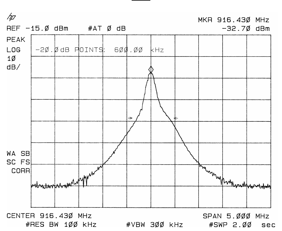
For transmitted radiated emission measurements, the sample was programmed to
continuously transmit a typical data. This mode was also used to capture the occupied
bandwidth plot shown below.
Plot 1
The field strength measurements were taken using an HP8596E spectrum analyzer, an
EMCO 3121C dipole set, an EMCO 3115 double ridge guide horn and an Avantek
UJ210 preamp. The device was scanned in both transmit and receive modes from
30MHz. to 10GHz. and all emissions within 30 dB. of the limits were noted.
The receiver in this device is a pulse sequenced TRF, clocked at approximately 1.54
MHz. and has no local oscillator. An effort was made to detect emissions that would be
harmonically related to the sequencer clock but none were found.
HS9-T8665C
4
The controller circuit has clock oscillators at 32 kHz. , 500kHz. and 8 MHz. These
frequencies and related harmonics were also investigated. Two frequencies related to
the 8 MHz. clock (32.00 MHz. and 40.00 MHz.) were detected but were greater than
30dB below the limit and are not recorded in the table.
At each detected emission frequency, the device was measured by rotating the
turntable and adjusting the antenna height over a range of 1 to 4 meters to obtain the
maximum output level. This procedure was performed with both horizontal and vertical
antenna polarizations for both of the setup positions shown in the test setup photos.
The peak reading for each frequency was recorded in the fourth column in Table 1
below.
CLIENT: HONEYWELL FCC ID: HS9-T8665C
EUT: DATA TRANSMITTER
PART 15.249 TEST DATE: 05-DEC-01
Ant.
Polar.
H/V
916.431 V 30.5 -44.14 46559 50000
1832.862 V 30.2 -91.17 200 500
2749.293 V 33.4 -93.66 217 500
3665.724 H 35.7 -97.21 188 500
4582.155 V 36.6 -100.83 138 500
5498.586 H 38.6 -104.54 113 500
6415.016 H 39.1 -111.06 56 500
7331.446 V 40.8 -117.52 33 500
Table 1
RADIATED EMISSIONS DATA
Frequency
In
MHz.
Peak
Power
uV/m@3m
Peak
reading
dBm
Ant.
Factor
dB
ANTENNA: DIPOLES/DRG HORN
Duty
Cycle
-dB
FCC
Limit
uV/m@3m
Corrected
Power
uV/m@3m
Measurements taken for weak emissions were performed by reducing the distance from
the measurement antenna to 1 meter and factoring –9.54dB into the calculation. This
method was used for the 7th and 8th harmonics.
C. OCCUPIED BANDWIDTH AND DUTY CYCLE
The occupied bandwidth measurement was made using an HP8596E spectrum
analyzer and plotted with an HP7475A pen plotter. The duty cycle correction factor for
this device is approximately –4dB, but since the peak readings for all detected
harmonics were below the limits, the duty cycle correction factor was not applied to the
calculations.