User Manual

User Guide
Wi-Fi Programmable
Thermostat
RTH6500WF Wi-Fi Series

69-2718EF—01 ii
In the box you will find
• Thermostat
• Wallplate (attached to thermostat)
• Screws and anchors
• Quick Start Guide
• Thermostat ID Card
• Wire labels
• User Guide
• Quick Reference Card

Welcome
Congratulations on your purchase of a
Honeywell Wi-Fi programmable thermostat.
When registered to Honeywell’s Total Connect
Comfort Solutions, you can remotely monitor
and control the heating and cooling system
in your home or business—you can stay
connected to your comfort system wherever
you go.
Honeywell’s Total Connect Comfort is the
perfect solution if you travel frequently, own
a vacation home, a business or manage an
Investment property or if you are simply looking
for peace of mind.

69-2718EF—01 2
This thermostat works with common 24 volt systems such as forced air, hydronic,
heat pump, oil, gas, and electric. It will not work with millivolt systems, such as a gas
fireplace, or with 120/240 volt systems such as baseboard electric heat.
MERCURY NOTICE: Do not place your old thermostat in the trash if it contains
mercury in a sealed tube. Contact the Thermostat Recycling Corporation at
www.thermostat-recycle.org or 1-800-238-8192 for information on how and
where to properly and safely dispose of your old thermostat.
NOTICE: To avoid possible compressor damage, do not run air conditioner if the
outside temperature drops below 50°F (10°C).
Need help?
Visit wifithermostat.com or call 1-855-733-5465 for assistance before returning the
thermostat to the store.
69-2718EF—01 3
About your new thermostat
Controls and Home screen
quick reference ............................................5
Preset energy-saving schedules ................. 6
Installation
Installing your thermostat ............................8
Connecting to your Wi-Fi network .............26
Registering your thermostat online ........... 31
Operation
Setting the the time and day ..................... 36
Setting the fan ........................................... 37
Selecting system mode .............................38
Adjusting program schedules ....................39
Overriding schedules temporarily .............40
Overriding schedules permanently ...........41
Unregistering thermostat...........................42
Disconnecting Wi-Fi ..................................43
Special features ........................................45
Setting functions and options ....................48
Appendices
Frequently asked questions ......................55
Troubleshooting ......................................... 61
Limited warranty ........................................67
Table of contents
69-2718EF—01 4
Features of your Wi-Fi thermostat
With your new thermostat, you can:
• Connect to the Internet to monitor and control your heating/cooling system
• View and change your heating/cooling system settings
• View and set temperature and schedules
• Receive alerts via email and get automatic upgrades
Your new thermostat provides:
• Smart Response Technology
• Compressor protection
• Heat/cool auto changeover
5 69-2718EF—01
M31586
HOLD
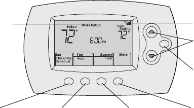
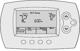
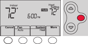
Controls and home screen quick reference
Once your Wi-Fi thermostat is installed, it will display the home screen. Portions of this
display will change depending on how you are viewing it.
The screen lights when you press any button. It stays lit for 8 seconds after you complete
changes.
Set up messages
describe steps in the
Wi-Fi set up process
Wi-Fi status
Set clock, day,
or schedule
Select fan
settings
Additional
settings
Temperature adjustment
buttons
Permanent override
button
Select system
mode
69-2718EF—01 6
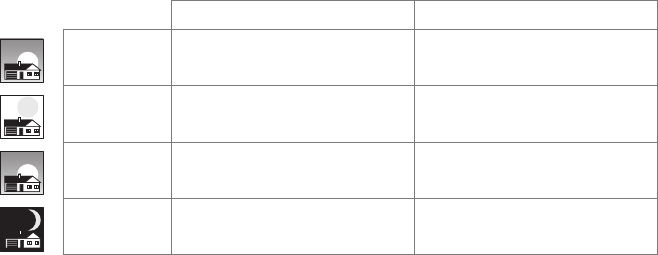
Preset energy-saving schedules
This thermostat is pre-set with energy-saving program settings for four time periods.
Using the default settings can reduce your heating/cooling expenses by as much as 33%
if used as directed. Savings may vary depending on geographic region and usage. To
change the settings, see pages 39–41.
Default Heat Settings Default Cool Settings
WAKE
6:00 am 70 °78 °
LEAVE
8:00 am 62 °85 °
RETURN
6:00 pm 70 °78 °
SLEEP
10:00 pm 62 °82 °
7 69-2718EF—01
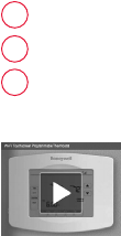
Setting up your thermostat
Setting up your Wi-Fi programmable thermostat is easy. It is preprogrammed and ready to
go as soon as it is installed and registered.
Install your thermostat.
Connect your home Wi-Fi network.
Register online for remote access.
Before you begin, you may want to watch a brief installation video. Use
the QR Code® at the front of this guide, or go to wifithermostat.com/support
2
3
1
69-2718EF—01 8
Installing your thermostat
You might need the following tools to install this thermostat:
• No. 2 Phillips screwdriver
• Small pocket screwdriver
• Pencil
• Level (optional)
• Drill and bits (3/16” for drywall,
7/32” for plaster) (optional)
• Hammer (optional)
• Electrical tape (optional)
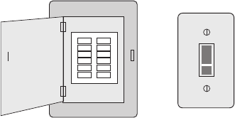
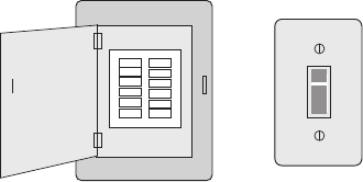
1 Switch OFF power to your
heating/cooling system.
Important! To protect your equipment,
switch OFF the power to your heating/
cooling system at the breaker box or
the system switch.
or
M31535
Circuit breaker
box
Heating/cooling
system power
switch
9 69-2718EF—01
C
C
MCR33823
If you have an older thermostat with a
sealed mercury tube, turn to page 2
for proper disposal instructions.
Installing your thermostat
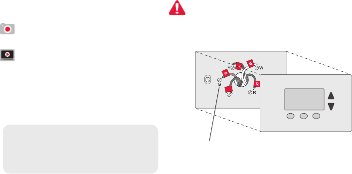
2 Remove old thermostat faceplate
and leave wires connected.
2a Take a picture of the wire
connections for later reference.
2b If no wire is connected to a terminal
labeled C or no C terminal exists
on the old thermostat, view the
Alternate Wiring videos at
wifithermostat.com/videos
Terminal
designation
Important! C wire is required and
is the primary power source for
your thermostat. Without a C wire,
your thermostat will not power up.
69-2718EF—01 10
Installing your thermostat
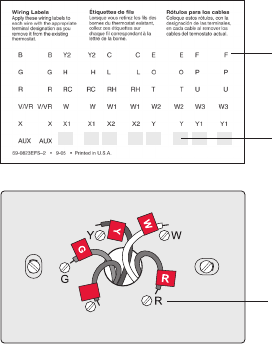
3 Label wires.
Do not label by wire color.Use
the supplied sticky tags to label
each wire as you disconnect it.
Label wires according to the old
thermostat terminal designations,
not by wire color.
Note: If no tag matches a wire
terminal label, write the terminal
label on a blank tag.
4 Remove wallplate.
Remove the old wallplate from
the wall after all wires have been
labeled and disconnected.
Terminal
designation
C
C
MCR31537
Blank sticky
tags
Sticky tags
11 69-2718EF—01
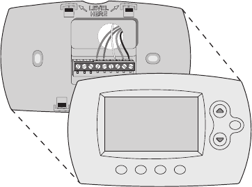
Installing your thermostat
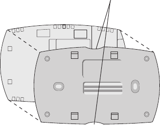
5 Separate Wi-Fi thermostat and its
wallplate.
On your new thermostat, grasp the
finger holds on the top and bottom of
the wallplate with one hand and the
thermostat (front) with the other hand.
Pull pieces apart.
Thermostat
Wallplate (back view)
Finger holds
M33856
PULL HERE
TO REMOVE
PULL HERE
TO REMOVE
69-2718EF—01 12
Installing your thermostat
6 Mount wallplate for Wi-Fi thermostat.
Mount your new wallplate using screws and anchors
included with the thermostat.
If necessary:
Drill 3/16-in holes for drywall.
Drill 7/32-in holes for plaster.
Note: You may be able to use your existing
wall anchors. Hold the wallplate up to the
existing anchors to check for alignment
Wallplate
MCR33857

13 69-2718EF—01
Important! The Wi-Fi thermostat requires a C wire to operate. The C, or common, wire
brings 24 VAC power to the thermostat. Many older mechanical or battery operated
thermostats do not require a C wire. If you don’t have a C wire, try:
• Looking for an unused wire that is pushed into the wall. Connect that wire to C and
check that it is connected to the 24 VAC common at your heating/cooling system.
Note: Not all heating/cooling systems label the 24 VAC common C. Check your system
manual or contact the manufacturer to find out which terminal is the 24 VAC common.
View the Alternate Wiring videos at wifithermostat.com/videos
Wiring
For conventional heating/cooling systems (natural gas, oil or electric furnace, air
conditioner), see page 14. See “Glossary” on page 64 for further definition.
For a heat pump system, see page 15. See “Glossary” on page 64 for further
definition.
Installing your thermostat
69-2718EF—01 14
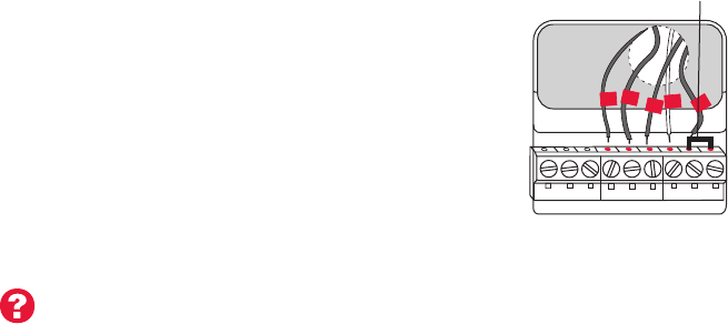
Installing your thermostat
Wiring (conventional system)
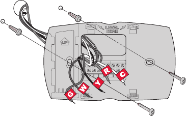
7A Wire the Wi-Fi thermostat to your conventional system.
a Starting with the C Wire, match the sticky tag on the
wire to the terminal labels.
You must have a C wire. See page 13.
b Loosen screw, insert wire on inside edge
of terminal, then tighten screw.
c Verify wire is firmly secured by gently
pulling on wire.
d Repeat steps a–c for all other wires.
e Push any excess wire back into the wall
opening after all wires are installed.
f Continue to page 20.
Labels don’t match? See alternate
wiring key on pages 16–17.
W2 GWYR RCK Y2 C
MCR33878
Y
HEAT PUMP
CONVENTIONAL
AUX/E GO/B YRRCK LC
C
G
W
R
Remove metal jumper
only if you have both
R and RC wires
Note: The wiring for your
application might be different
from the shown above.
15 69-2718EF—01
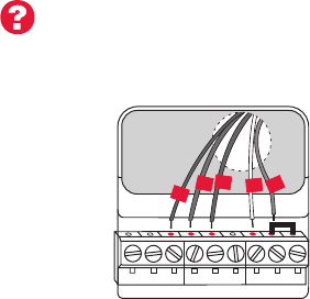
Installing your thermostat
Wiring (heat pump system only)
7B Wire Wi-Fi thermostat to your heat pump.
a Starting with the C Wire, match the sticky tag on the wire to the terminal labels.
You must have a C wire. See page 13.
b Loosen screw, insert wire on inside edge
of terminal, then tighten screw.
c Verify wire is firmly secured by gently
pulling on wire.
d Repeat steps a–c for all other wires.
e Push any excess wire back into the wall
opening after all wires are installed
.
f
Continue to page 20.
Note: If old thermostat has separate wires on AUX and
E, place both wires into the E/AUX terminal.
If old thermostat has wire on AUX with a jumper to E,
place wire on E/AUX terminal. No jumper is required.
Labels don’t match? See alternate
wiring key on pages 18–19.
MCR33877
G
O
Y
R
HEAT PUMP
AUX/E GO/B YRRCK LC
Aux
Note: The wiring for your
application might be different
from the wiring shown above.
69-2718EF—01 16
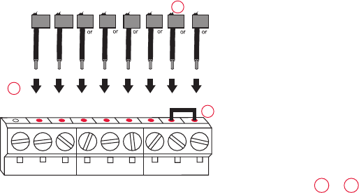
Installing your thermostat
Alternate wiring (conventional system)
Use this if your wire labels don’t match the terminal labels.
Note: You must have
a C wire or equivalent.
See page 13.
See key to 1 – 3
on page 17.
Y2
R
4M
V
RHY1
H
W1F
RYWG
RC
W2
W2 GWYRRC
Y2 C
MCR33885
CONVENTIONAL
C
B
C1
X
K
1
2
3

17 69-2718EF—01
Installing your thermostat
Do not use K terminal. For future use.
If your old thermostat had both R and RH wires, remove metal jumper.
Connect the R wire to the RC terminal, and the RH wire to the R terminal.
Remove metal jumper connecting R and RC only if you must connect both
R and RC.
Alternate wiring key (conventional system)
2
3
1
69-2718EF—01 18
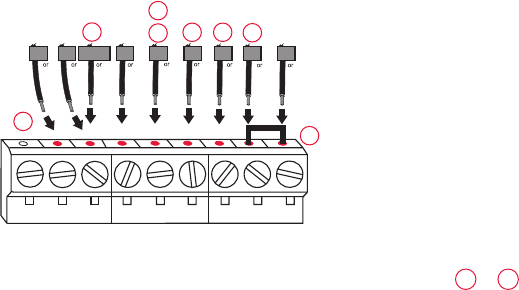
Installing your thermostat
Alternate wiring (heat pump system only)
Use this if your wire labels don’t match the terminal labels.
Note: You must have
a C wire or equivalent.
See page 13.
See key to 1 – 7
on page 19.
MCR33886
EAUX
XW FH
B
W1
W2
X2
LOG
F
C
R
VRM
VY1
B
X
RY
RC
HEAT PUMP
AUX/E GO/B YRRCK LC
1
2
3
4
7
6
5
4

19 69-2718EF—01
Installing your thermostat
Alternate wiring key (heat pump system only)
Do not use K terminal. For future use.
If old thermostat has separate wires on AUX and E, place both wires into the E/AUX terminal. If
old thermostat has wire on AUX with a jumper to E, place wire on E/AUX terminal. No jumper is
required.
If your old thermostat had an O wire and not a B wire, attach the O wire to the O/B terminal.
If your old thermostat had separate O and B wires, attach the B wire to the C terminal. If
another wire is attached to the C terminal, check wifithermostat.com for help. Attach the O wire
to the O/B terminal.
If your old thermostat had separate Y1, W1 and W2 wires, check wifithermostat.com for help.
If your old thermostat had both V and VR wires, check wifithermostat.com for help.
Leave metal jumper between R and RC terminals in place.
2
3
1
4
5
6
7
69-2718EF—01 20
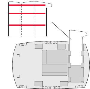
Installing your thermostat
8 Insert quick reference card.
Fold quick reference card
along score lines, and slide
it into the slot on the back of
the thermostat.
Back of thermostat
Quick
reference
card
MCR33916
MCR33858
21 69-2718EF—01
Installing your thermostat
9 Attach thermostat to wallplate.
Align the thermostat to the wallplate
and then snap into place.
M33860
HOLD
69-2718EF—01 22
Installing your thermostat
10 Switch heating/cooling system ON.
Important!
10a Verify that the C wire is
connected at the thermostat
and at the heating/cooling
system.
10b Make sure the heating/
cooling system door is firmly
secured.
10c Switch power back ON for
your heating/cooling system
at the breaker box or its
power switch.
M31544
or
Circuit breaker
box
Heating/cooling
system power
switch
23 69-2718EF—01
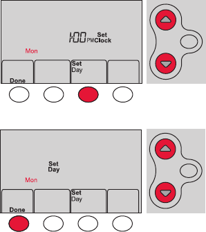
Installing your thermostat
11 Set clock to current day and time.
11a Press s or t to set clock.
11b Press Set Day.
11c Press s or t to select the
day of week.
11d Press Done to save.
(Press and hold a st button to
quickly change a setting.)
MCR33908
HOLD
MCR33909
HOLD

69-2718EF—01 24
Installing your thermostat
12 Determine your heating/cooling system type.
Important! Heating/cooling system type must be set so that your
thermostat operates properly and does not damage your system.
12a If your system type is conventional single stage (natural gas-powered single
stage with a/c), continue to “Connecting to your Wi-Fi network” on page 26.
12b If your system is:
• Conventionalmultistageheatandcool
• Anytypeofheatpump
• Hydronic
• Other
You MUST change the system type by setting system function 1. See page 48
to match your thermostat to your system type.
If you are not sure of your
heating/cooling system type
or have other questions, go
to wifithermostat.com/support
25 69-2718EF—01
Installing your thermostat
MCR33880
Congratulations! Your thermostat is operational.
13 Test your thermostat
13a Press the
System
button to change to
heating or cooling and begin operation.
13b For remote access to your thermostat,
continue to
“Connecting to your Wi-Fi
network” on page 26.
Heating/cooling system not turning
on? Refer to page 62 or FAQ at
wifithermostat.com/support

69-2718EF—01 26
Connecting to your Wi-Fi network
To complete this process, you must have a wireless device connected to your home
wireless network. Any of these device types will work:
• Tablet (recommended)
• Laptop (recommended)
• Smartphone
If you get stuck... at any point in this procedure, restart the thermostat by
removing the thermostat from the wallplate, wait for 10 seconds, and snap it back
onto the wallplate. Go to Step 1 in this procedure, starting on page 27.
View the Wi-Fi Enrollment video at wifithermostat.com/videos
27 69-2718EF—01
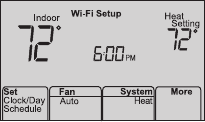
1 Connect to your thermostat.
1a Make sure the thermostat displays
Wi-Fi Setup.
1b On the wireless device (laptop, tablet,
smartphone), view the list of available Wi-Fi
networks.
1c Connect to the network called
NewThermostat_123456 (the number will
vary).
Note: If you are asked to specify a home, public, or
office network, select Home Network.
Connecting to your Wi-Fi network
M33852
HOLD
69-2718EF—01 28
Connecting to your Wi-Fi network
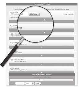
2 Join your home network.
2a Open your web browser to access the
Thermostat Wi-Fi Setup page. The browser
should automatically direct you to the correct
page; if it does not, go to http://192.168.1.1
2b Find the name of your home network on this
page and select it.
Note: Some routers have enhanced features such as
guest networks; use your home network.
2c Complete the instructions for joining your Wi-Fi
network and click on the Connect button.
(Depending on your network setup, you may see
an instruction such as Enter Password for your home network.)
Note: If you did not correctly connect to the thermostat, you may see
your home router page. If so, return to Step 1.
M31567
29 69-2718EF—01
Connecting to your Wi-Fi network
Note: If your Wi-Fi network does not appear in the list on the Thermostat Wi-Fi Setup
page:
• Try performing a network rescan by pressing the Rescan button. This is helpful in
areas with a lot of networks.
• If you are connecting to a hidden network, then enter the network SSID in the
textbox, select the encryption type from the drop down menu, and click on the
Add button. This manually adds the network to the top of the list. Click on the new
network in the list and enter the password if necessary. Click on Connect to join the
network.
69-2718EF—01 30
Connecting to your Wi-Fi network
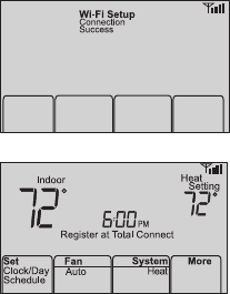
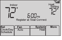
3 Make sure your thermostat is connected.
While the connection is in process, your thermostat
will flash Wait for up to 3 minutes. When the
connection is complete, the display will show Wi-Fi
Setup Connection Success. The Wi-Fi signal strength will
appear in the top-right corner.
After about 60 seconds, the home screen will appear
and Register at Total Connect will flash until registration
is complete.
If you don’t see these messages, see page 26.
To register online for remote access to your thermostat
continue on page 31.
Note: If the thermostat displays Connection Failure or continues to display
Wi-Fi Setup, confirm you correctly entered your home network password in
step 2. If correct, refer to the FAQ at wifithermostat.com/support
M33875
M33876

31 69-2718EF—01
Registering your thermostat online
M31570
To view and set your Wi-Fi thermostat
remotely, you must have a Total Connect
Comfort account. Use the following steps.
1 Open the Total Connect Comfort web site.
Go to mytotalconnectcomfort.com
View the Wi-Fi Thermostat Registration
video at wifithermostat.com/videos

69-2718EF—01 32
Registering your thermostat online
2 Login or create an account.
If you have an account,
click Login
– or –
click Create An Account
.
2a Follow the instructions on the screen.
2b Check your email for an activation
message from My Total Connect
Comfort. This may take several minutes.
Note: If you do not receive a response, check
your junk mailbox or use an alternate e-mail
address.
2c Follow activation instructions in the
email.
2d Log in.
M31571
33 69-2718EF—01
Registering your thermostat online
3 Register your Wi-Fi thermostat.
After you are logged in to your Total Connect Comfort account,
register your thermostat.
3a Follow the instructions on the
screen. After adding your
thermostat location, you must enter
the thermostat’s unique identifiers:
• MACID
• MACCRC
Note: These IDs are listed on the
Thermostat ID Card included in the
thermostat package. The IDs are not
case sensitive.
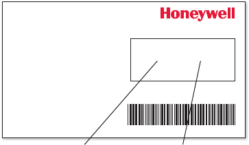
® U.S. Registered Trademark.
© 2012 Honeywell International Inc.
69-2723EFS—01 M.S. 04-12
Printed in U.S.A.
HONEYWELL MODEL:
MAC ID: MAC CRC:
69-2723EFS-01
Thermostat ID Card
Use the MAC ID and CRC ID to register
this product at mytotalconnectcomfort.com
Carte d’identification de thermostat
Utilisez l’identication MAC et l’identication CRC pour
enregistrer ce produit à mytotalconnectcomfort.com
Tarjeta de identificación del termostato
Utilice la identicación MAC y la identicación CRC para
inscribir este producto en mytotalconnectcomfort.com
MAC ID MAC CRC
69-2718EF—01 34
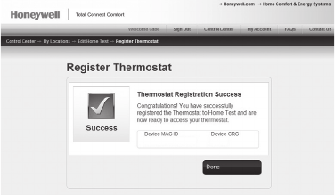
Registering your thermostat online
3b When the thermostat is
successfully registered,
the Total Connect Comfort
registration screen will
display a SUCCESS
message.
In the thermostat display, you
will see Setup Complete for
about 90 seconds.
35 69-2718EF—01
Registering your thermostat online
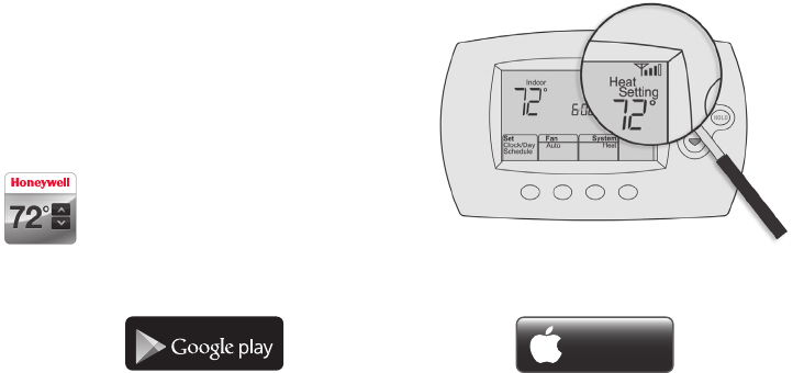
3c Also notice that your thermostat displays
its signal strength.
Congratulations! You’re done.
You can now control your thermostat from
anywhere through your tablet, laptop, or
smartphone
Total Connect Comfort free app is
available for Apple® iPhone®, iPad® and
iPod touch® devices at iTunes® or at
Google Play® for all Android™ devices.
GET IT ON
Download on
iTunes
69-2718EF—01 36
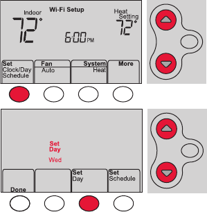
1 Press Set Clock/Day/Schedule, then press s
or t to set clock.
2 Press Set Day, then press s or t to select
the day of week.
3 Press Done to save.
Note: If the Set Clock/Day/Schedule option is not
displayed, press Done.
Note: If the display flashes Set Clock, the
thermostat will follow your settings for the
Monday “Wake” time period until you reset the
time and day.
Setting the time and day
MCR33855
HOLD
HOLD
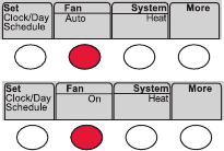
37 69-2718EF—01
Press Fan to select On or Auto (toggle to
re-select).
Auto
: Fan runs only when the heating or
cooling system is on. Auto is the most
commonly used setting.
On: Fan is always on.
Note: Options may vary depending on your
heating/cooling equipment.
Setting the fan
MCR33895
69-2718EF—01 38
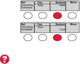
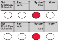
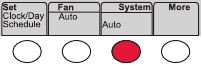
Selecting system mode
Note: Depending on how
your thermostat was installed,
you may not see all system
settings.
Press System to select:
Heat: Controls only the heating system.
Cool: Controls only the cooling system.
Off: Heating/cooling systems are off.
Auto: Selects heating or cooling depending on
the indoor temperature.
Em Heat (heat pumps with aux. heat):
Controls auxiliary/emergency heat.
Compressor is off.
MCR33880
39 69-2718EF—01
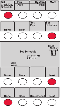
Adjusting program schedules
1 Press Set Clock/Day/Schedule, then Set Schedule.
2 Press s or t to set your Monday (Mon) Wake
time, then press Next.
3 Press s or t to set the temperature for this
period, then press Next.
4 Set time and temperature for the next time
period (Leave). Repeat Steps 2 and 3 for each
time period.
5 Press Next to set time periods for the next day.
Repeat Steps 2 through 4 for each day.
6 Press Done to save and exit.
Note: Make sure the thermostat is set to the
system mode you want to program (Heat or Cool).
MCR33892
69-2718EF—01 40
Overriding schedules temporarily
Press s or t to immediately adjust the
temperature.
The new temperature will be maintained only
until the next programmed time period begins.
To cancel the temporary setting at any time,
press Cancel. The program schedule will
resume.
MCR33896
HOLD
41 69-2718EF—01
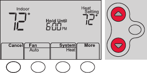
Overriding schedules permanently
1 Press HOLD to permanently adjust the
temperature. This will turn off the program
schedule.
2 Press s or t to adjust the temperature
setting. The temperature you set will
be maintained 24 hours a day until you
manually change it or press Cancel to
resume the program schedule
MCR33897
HOLD
69-2718EF—01 42
Unregistering thermostat
If you remove the thermostat from your
Total Connect Comfort website account
(for example, you’re moving and leaving
the thermostat behind), the thermostat will
display Register at Total Connect until it is
re-registered. M33876
43 69-2718EF—01
Disconnecting Wi-Fi
Replacing your router
If you disconnect the thermostat from your Wi-Fi
network:
1 Enter system setup (see page 48).
2 Change setting 39 to 0 (see page 54).
The screen will display Wi-Fi Setup.
Re-connect to a Wi-Fi network by following the steps on page 26.
Turning Wi-Fi off
If you do not plan to control the thermostat remotely, you can remove the Wi-Fi Setup
message from the screen:
1 Enter system setup (see page 48).
2 Change setting 38 to 0 (see page 54). Wi-Fi Setup will be removed from the screen.
If you want to connect to the Wi-Fi network later, change setting 38 back to 1.
M33855
69-2718EF—01 44
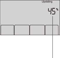
Software updates
Honeywell periodically issues updates to the software for
this thermostat. The updates occur automatically through
your Wi-Fi connection. All your settings are saved, so
you will not need to make any changes after the update
occurs.
While the update is taking place, your thermostat screen
flashes Updating and shows the percentage of the update
that has occurred. When the update is complete, your
home screen will appear as usual.
Note: If you are not connected to Wi-Fi, you will not get
automatic updates.
M34001
Percentage of
update complete
45 69-2718EF—01
M33881
Smart Response Technology
This feature allows the thermostat to “learn”
how long the heating/cooling system takes to
reach programmed temperature settings, so
the temperature is reached at the time you set.
For example: Set the Wake time to 6:00 am,
and the temperature to 70°. The heat will come
on before 6:00 am, so the temperature is 70°
by 6:00 am.
Note: System setting function 13 controls
Smart Response Technology. See “Smart
Response Technology” on page 52.
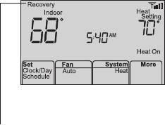
The message Recovery
is displayed when the
system is activated before
a scheduled time period.
69-2718EF—01 46
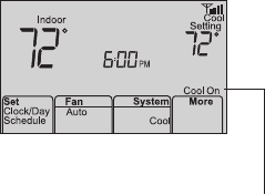
Compressor protection
This feature forces the compressor to wait
a few minutes before restarting, to prevent
equipment damage.
The message Cool On (or
Heat On for a heat pump)
will flash during the wait
time.
M33882
47 69-2718EF—01
Auto changeover
This feature is used in climates where both
air conditioning and heating are used on the
same day.
When the system is set to Auto,
the thermostat automatically
selects heating or cooling
depending on the indoor temperature.
Heat and cool settings must be at least
3 degrees apart. The thermostat will
automatically adjust settings to maintain this
3-degree separation.
Note: System setting function 12 controls
Auto changeover. See “Manual/Auto
Changeover” on page 51.
MCR33893
69-2718EF—01 48
Setting functions and options
You can change options for a number of system functions. Available functions depend on
the type of system you have. The functions, along with available options are described on
pages 50–54.
This thermostat is pre-set for a single-stage heating/cooling system.
Setting function 1 for a heat pump will adjust the default settings.
49 69-2718EF—01
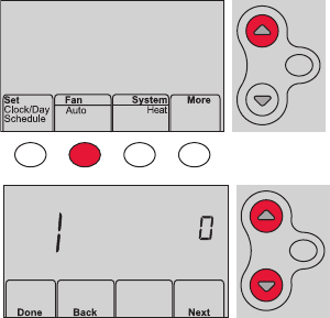
Setting functions and options
1 Press Fan and s simultaneously and hold
for approximately 3 seconds. The screen
will change to display two numbers and
the button designations will be Done, Back,
blank, Next.
2 Press Next until you see the function
number—the larger number on the left—
you want to set.
3 Change options for any function by
pressing s or t until the correct option
(smaller number on right) is displayed.
4 Repeat Steps 2 and 3 until you have set all
functions that you wish to change.
5 When you have made all changes, press
Done to save and exit.
HOLD
MCR33883
MCR33884
HOLD

69-2718EF—01 50
System setup
(See page 48 for instructions.)
Function Settings & Options
1Select System
Type
If you are not sure
of your heating/
cooling system
type or have other
questions, go to
withermostat.com
0 Heat/cool: Gas, oil or electric heating with central air conditioning.
1 Heat pump: Heat pump without backup or auxiliary heat.
2 Heat only: Gas, oil or hot water heat without central air conditioning.
3 Heat only with fan: Gas, oil or electric heat without central air
conditioning.
4 Cool only: Central air conditioning only.
5 Heat pump: Heat pump with backup or auxiliary heating.
6 Heat/Cool Multiple stages: 2 heat stages (wires on W and W2), 2
cooling stages (wires on Y and Y2).
7 Heat/Cool Multiple stages: 2 heat stages (wires on W and W2), 1
cooling stage (wire on Y).
8 Heat/Cool Multiple stages: 1 heat stage (wires on W), 2 cooling stages
(wire on Y and Y2).
2Heat Pump
Changeover Valve
(for heat pumps
only)
0 Cooling changeover valve: Use this setting if you connected a wire
labeled “O” to the O/B terminal.
1 Heating changeover valve: Use this setting if you connected a wire
labeled “B” to the O/B terminal.

51 69-2718EF—01
(See page 48 for instructions.)
System setup
Function Settings & Options
3Heating Fan
Control
0 Gas or oil heat: Use this setting if you have a gas or oil heating system
(system controls fan operation).
1 Electric heat: Use this setting if you have an electric heating system
(thermostat controls fan operation).
5Heating Cycle
Rate
5 Gas or oil furnace: Standard gas/oil furnace (less than 90% efficiency).
9 Electric furnace: Electric heating systems.
3 Hot water or high-efficiency furnace: Hot water system or gas furnace
(more than 90% efficiency).
1 Gas/oil steam or gravity system: Steam or gravity heat systems.
6Heating Cycle
Rate Stage 2
12 Manual/Auto
Changeover
See page 47 for
more information.
0 Manual changeover (Heat/Cool/Off).
1 Automatic changeover (Heat/Cool/Auto/Off). Automatically turns on Heat
or Cool based on room temperature. Note: System maintains minimum
3°F difference between heat and cool settings.
69-2718EF—01 52
System setup
(See page 48 for instructions.)
Function Settings & Options
13 Smart Response
Technology
See page 45 for
more information.
1 On
0 Off
14 Temperature For-
mat (°F/°C)
0 Fahrenheit
1 Celsius
16 Schedule Options 1 Program schedule is on (7-day programmable).
0 Program schedule is off. Thermostat can not be programmed.

53 69-2718EF—01
System setup
(See page 48 for instructions.)
Function Settings & Options
36 Device Name
This name will
identify the
thermostat when
you view it remotely.
If you register
multiple thermostats,
give each one a
different name.
52 = Thermostat
1 Basement 16 Exercise Room 30 Library 44 Porch
2 Bathroom 17 Family Room 31 Living Room 45 Rec Room
3 Bathroom 1 18 Fireplace 32 Lower Level 46 Sewing Room
4 Bathroom 2 19 Foyer 33 Master Bath 47 Spa
5 Bathroom 3 20 Game Room 34 Master Bed 48 Storage Room
6 Bedroom 21 Garage 35 Media Room 49 Studio
7 Bedroom 1 22 Great Room 36 Music Room 50 Sun Room
8 Bedroom 2 23 Guest Room 37 Nursery 51 Theater
9 Bedroom 3 24 Gym 38 Office 52 Thermostat
10 Bedroom 4 25 Kid's Room 39 Office 1 53 Upper Level
11 Boat House 26 Kitchen 40 Office 2 54 Utility Room
12 Bonus Room 27 Kitchen 1 41 Pantry 55 Walk In Closet
13 Computer Room 28 Kitchen 2 42 Play Room 56 Wine Cellar
14 Den 29 Laundry Room 43 Pool Room 57 Workshop
15 Dining Room

69-2718EF—01 54
System setup
(See page 48 for instructions.)
Function Settings & Options
38 Wi-Fi On/Off 1 Wi-Fi is on and can be connected to a Wi-Fi network.
0 Wi-Fi is off. Thermostat cannot be connected to a Wi-Fi network. If you
are not connecting the thermostat to a Wi-Fi network this will remove the
text Wi-Fi Setup from the messaging center.
39 Wi-Fi Connection 1 Connected to Wi-Fi network. This is set automatically when the
thermostat is connected to the Wi-Fi network.
0 Set to 0 to disconnect from the Wi-Fi network.
42 Show period and
day of week
0 Period and day are not shown on the home screen.
1 Period and day are shown on the home screen.
85 Restore Schedule
Defaults
0 Continue using programmed schedule.
1 Restore thermostat program to energy saving settings
90 Restore Original
Settings
0 No
1 Disconnects thermostat from Wi-Fi and restores original settings (erases
customizations).
55 69-2718EF—01
Frequently asked questions
:Q Will my thermostat still work if I lose my Wi-Fi connection?
:AYes, the thermostat will operate your heating and/or cooling system with or without Wi-Fi.
:Q How do I find the password to my router?
:AContact the manufacturer of the router or check the router documentation.
:Q Why am I not seeing my Wi-Fi setup page?
:AYou are probably connected only to your router, not to your thermostat. Try connecting to the
thermostat again.
:Q Why isn’t my thermostat connecting to my Wi-Fi router even though it is very close to the
thermostat?
:AVerify that the password entered for the Wi-Fi router is correct.
69-2718EF—01 56
Frequently asked questions
:Q Where can I find my MAC ID and MAC CRC codes?
:AThe MAC ID and MAC CRC numbers are included on a card packed with the thermostat or on the
back of the thermostat (visible when removed from wallplate). Each thermostat has a unique MAC
ID and MAC CRC.
:Q My thermostat is unable to register to the Total Connect Comfort website.
:AVerify that the thermostat is correctly enrolled on your home Wi-Fi network. The message center
will display Wi-Fi Setup or Register at Total Connect. You might also see the Wi-Fi Signal strength
icon. Verify that the Wi-Fi router has a good internet connection. On your computer, verify that
you can open the site at mytotalconnectcomfort.com
If you cannot open the site, switch off the internet modem for a few seconds, then power it
back on.
57 69-2718EF—01
Frequently asked questions
:Q I registered on the Total Connect Comfort website but was unable to login using my new
account.
:ACheck your email and ensure that you received an activation email. Follow the instructions to
activate your account and then login to the website.
:Q I have signed up on the Total Connect Comfort website and have not received a
confirmation email.
:ACheck for the email in your Junk or Deleted folder.
:Q Is there a way to extend the signal strength?
:AMost standard routers can be set up to be a repeater. You can also purchase and install a Wi-Fi
repeater.
For more FAQs, see wifithermostat.com/support
69-2718EF—01 58
Troubleshooting
Lost Signal
If the no-Wi-Fi indicator displays in place of the
Wi-Fi strength indicator in the upper right hand
corner of the home screen:
• Check another device to be sure Wi-Fi is
working in your home; if not, call your Internet
Service Provider.
• Move the router.
• Restart the thermostat: remove it from the
wallplate, wait 10 seconds, and snap it
back onto the wallplate. Return to Step 1 of
Connecting to your Wi-Fi network.
M33997
M
33997
59 69-2718EF—01
Troubleshooting
Error Code Action
E01 During Wi-Fi Setup, the router
lost power.
• Ensureyourrouterhaspower.
• Iftryingtoconnecttoahiddenormanuallyaddednetwork,
confirm the router has power and is working.
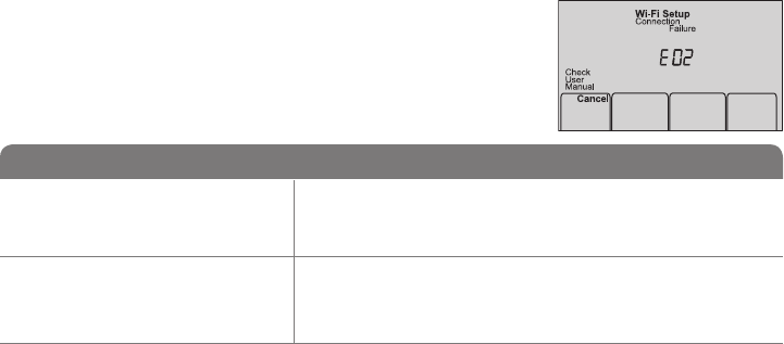
E02 Invalid Wi-Fi password. This
code displays for 30 seconds,
then the thermostat will re-enter
Wi-Fi Setup mode.
• Re-enterpasswordforyourhomeWi-Finetwork.
• Repeatsetupprocessandconfirmyourpasswordforyourhome
Wi-Fi network.
Error Codes
For certain problems, the thermostat screen will display
a code that identifies the trouble. Initially, error codes are
displayed alone in the time area of the screen; after a
few minutes, the home screen is displayed and the code
alternates with the time.
M33999
69-2718EF—01 60
Troubleshooting
M33998
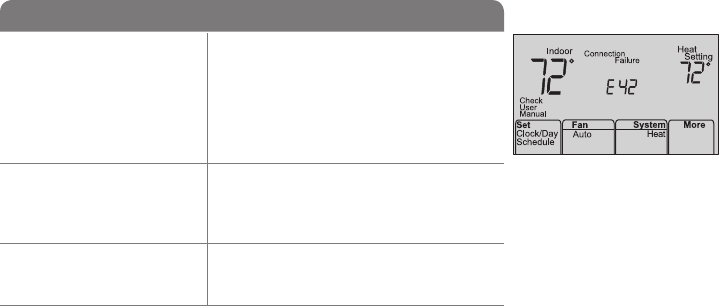
Error Code Action
E42 Router is not issuing
an IP address to the
thermostat.
• Waitfor30minutes,connectioncantake
several minutes.
• Ifstillnoconnection,removethermostat
from wallplate for 10 seconds, then
reconnect it (see page 26).
• Verifyyourrouteriscorrectlysetupto
automatically give IP addresses.
E43 No internet connection.
Thermostat cannot
communicate to Total
Connect Comfort.
• MakesuretheInternetcableisplugged
in.
• Reboottherouter.
E99 General error Remove thermostat from wallplate for
10 seconds, then reconnect it (see page
26).

61 69-2718EF—01
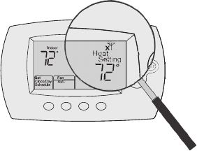
If you have difficulty with your thermostat, please try the following suggestions.
Most problems can be corrected quickly and easily.
Display is
blank
• Checkcircuitbreakerandresetifnecessary.
• Makesurepowerswitchatheatingandcoolingsystemison.
• Makesurefurnacedoorisclosedsecurely.
• MakesureCwireisconnected(seepage13).
Cannot change
system setting
to Cool
• CheckFunction 1: System Type to make sure it is set to match your heating
and cooling equipment (see page 50).
Fan does
not turn on
when heat is
required
• CheckFunction 3: Heating Fan Control to make sure it is set to match your
heating equipment (see page 51).
Cool On or Heat
On is flashing
on the screen
• Compressorprotectionfeatureisengaged.Wait5minutesforthesystemto
restart safely, without damage to the compressor.
Troubleshooting

69-2718EF—01 62
Troubleshooting
Heat pump
issues cool air
in heat mode,
or warm air in
cool mode
• CheckFunction 2: Heat Pump Changeover Valve to make sure it is properly
configured for your system (see page 50).
Heating or
cooling system
does not
respond
• PressSystem to set system to Heat. Make sure the temperature is set higher
than the Inside temperature.
• PressSystem to set system to Cool. Make sure the temperature is set lower
than the Inside temperature.
• Checkcircuitbreakerandresetifnecessary.
• Makesurepowerswitchatheating&coolingsystemison.
• Makesurefurnacedoorisclosedsecurely.
• Wait5minutesforthesystemtorespond.

63 69-2718EF—01
Troubleshooting
Heating system
is running in
cool mode
• CheckFunction 1: System Type to make sure it is set to match your heating
and cooling equipment (see page 50).
Heating
and cooling
equipment are
running at the
same time
• CheckFunction 1: System Type to make sure it is set to match your heating
and cooling equipment (see page 50).
• Graspandpullthermostatawayfromwallplate.Checktomakesurebare
wires are not touching each other.
• Checkthermostatwiringiscorrect.
69-2718EF—01 64
Glossary
C wire
The “C” or common wire brings 24 VAC power to the thermostat from the heating/cooling system.
Some older mechanical or battery operated thermostats may not have this wire connection. It is
necessary for establishing a Wi-Fi connection to your home network.
Heat Pump heating/cooling system
Heat pumps are used to heat and cool a home. If your old thermostat has a setting for auxiliary or
emergency heat, you likely have a heat pump.
Conventional heating/cooling system
Non–heat pump type systems; these include air handlers, furnaces or boilers that run on natural gas,
oil or electricity. They may or may not include an air conditioner.
Jumper
A small piece of wire that connects two terminals together.
MAC ID, MAC CRC
Alphanumeric codes that uniquely identify your thermostat.
QR Code®
Quick response code. A two-dimensional,machine-readable image. Your wireless device can read
the black and white pattern in the square and link its browser directly to a web site. QR Code is a
registered trademark of DENSO WAVE INCORPORATED.
65 69-2718EF—01
Regulatory information
FCC Compliance Statement (Part 15.19) (USA only)
This device complies with Part 15 of the FCC Rules.
Operation is subject to the following two conditions:
1 This device may not cause harmful interference, and
2 This device must accept any interference received,
including interference that may cause undesired
operation.
FCC Warning (Part 15.21) (USA only)
Changes or modifications not expressly approved by the
party responsible for compliance could void the user’s
authority to operate the equipment.
FCC Interference Statement (Part 15.105 (b))
(USA only)
This equipment has been tested and found to comply
with the limits for a Class B digital device, pursuant to
Part 15 of the FCC Rules. These limits are designed
to provide reasonable protection against harmful
interference in a residential installation. This equipment
generates uses and can radiate radio frequency energy
and, if not installed and used in accordance with the
instructions, may cause harmful interference to radio
communications. However, there is no guarantee that
interference will not occur in a particular installation. If
this equipment does cause harmful interference to radio
or television reception, which can be determined by
turning the equipment off and on, the user is encouraged
to try to correct the interference by one of the following
measures:
• Reorientorrelocatethereceivingantenna.
• Increasetheseparationbetweentheequipmentand
receiver.
• Connecttheequipmentintoanoutletonacircuit
different from that to which the receiver is connected.
• Consultthedealeroranexperiencedradio/TV
technician for help.
69-2718EF—01 66
Regulatory information
Thermostats
To comply with FCC and Industry Canada RF exposure
limits for general population/ uncontrolled exposure, the
antenna(s) used for these transmitters must be installed
to provide a separation distance of at least 20 cm from
all persons and must not be co-located or operating in
conjunction with any other antenna or transmitter.
Section 7.1.2 of RSS-GEN
Under Industry Canada regulations, this radio transmitter
may only operate using an antenna of type and
maximum (or lesser) gain approved for the transmitter by
Industry Canada. To reduce potential radio interference
to other users, the antenna type and its gain should
be so chosen that the equivalent isotropically radiated
power (e.i.r.p.) is not more than that necessary for
successful communication.
Section 7.1.3 of RSS-GEN
Operation is subject to the following two conditions:
1 this device may not cause interference, and
2 this device must accept any interference, including
interference that may cause undesired operation of the
device.
67 69-2718EF—01
1-year limited warranty
Honeywell warrants this product, excluding battery, to be free from defects in the workmanship or materials, under normal use and
service, for a period of one (1) year from the date of purchase by the consumer. If at any time during the warranty period the product is
determined to be defective or malfunctions, Honeywell shall repair or replace it (at Honeywell’s option).
If the product is defective,
(i) return it, with a bill of sale or other dated proof of purchase, to the place from which you purchased it; or
(ii) call Honeywell Customer Care at 1-855-733-5465. Customer Care will make the determination whether the product should be
returned to the following address: Honeywell Return Goods, Dock 4 MN10-3860, 1885 Douglas Dr. N., Golden Valley, MN 55422, or
whether a replacement product can be sent to you.
This warranty does not cover removal or reinstallation costs. This warranty shall not apply if it is shown by Honeywell that the defect or
malfunction was caused by damage which occurred while the product was in the possession of a consumer.
Honeywell’s sole responsibility shall be to repair or replace the product within the terms stated above. HONEYWELL SHALL NOT
BE LIABLE FOR ANY LOSS OR DAMAGE OF ANY KIND, INCLUDING ANY INCIDENTAL OR CONSEQUENTIAL DAMAGES
RESULTING, DIRECTLY OR INDIRECTLY, FROM ANY BREACH OF ANY WARRANTY, EXPRESS OR IMPLIED, OR ANY OTHER
FAILURE OF THIS PRODUCT. Some states do not allow the exclusion or limitation of incidental or consequential damages, so this
limitation may not apply to you.
THIS WARRANTY IS THE ONLY EXPRESS WARRANTY HONEYWELL MAKES ON THIS PRODUCT. THE DURATION OF ANY
IMPLIED WARRANTIES, INCLUDING THE WARRANTIES OF MERCHANTABILITY AND FITNESS FOR A PARTICULAR PURPOSE,
IS HEREBY LIMITED TO THE ONE-YEAR DURATION OF THIS WARRANTY. Some states do not allow limitations on how long an
implied warranty lasts, so the above limitation may not apply to you.
This warranty gives you specific legal rights, and you may have other rights which vary from state to state.
If you have any questions concerning this warranty, please write Honeywell Customer Relations, 1985 Douglas Dr, Golden Valley, MN
55422 or call 1-855-733-5465. In Canada, write Retail Products ON15-02H, Honeywell Limited/Honeywell Limitée, 35 Dynamic Drive,
Toronto, Ontario M1V4Z9.

Automation and Control Systems
Honeywell International Inc.
1985 Douglas Drive North
Golden Valley, MN 55422
wifithermostat.com
® U.S. Registered Trademark.
Apple, iPhone, iPad, iPod touch and iTunes are trademarks of Apple Inc.
All other trademarks are the property of their respective owners.
© 2012 Honeywell International Inc.
69-2718EF—01 M.S. 08-12
Printed in U.S.A.
69-2718EF-01