Ademco W8735ER01 Model W8735 Envirocom Wireless Bridge User Manual
Honeywell International Inc Model W8735 Envirocom Wireless Bridge
Ademco >
User Manual
INSTALLATION INSTRUCTIONS
66-1202-01
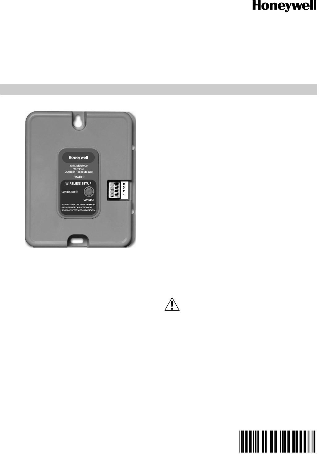
W8735ER Wireless Outdoor Reset
Module
APPLICATION
The W8735ER Wireless Outdoor Reset Module, when
connected to the C7089R1013 Wireless Outdoor Sensor,
works with any AquaReset enabled Aquastat® such as the
L7224/48 Aquastat, S9360/61/80 Integrated Boiler Control,
and R7910 SOLA Control via the EnviraCOM™ 3-wire bus.
The Wireless Outdoor Reset Module enables efficiency
control functionality, such as Outdoor Temperature Reset,
Boost function, and Warm Weather Shutdown function to
generate average operational savings of up to 15%.
SPECIFICATIONS
Electrical Ratings: Voltage: 24 Vac, 60 Hz.
Environmental Ratings:
Temperature: -30 °F to +150 °F (-34 °C to +66 °C).
Humidity: 0 to 95% relative humidity, non-condensing.
Accessories (Can be ordered separately):
C7089R1013 Wireless Outdoor Temperature Sensor
FEATURES
• RedLink™ wireless communication protocol
• Fast wireless connection to outdoor sensor
• Enables Boiler Outdoor Temperature Reset
• Enables Warm Weather Shutdown
• Enables Boost Override
• Simple low-voltage, 3-wire installation to combustion
control (3 EnviraCOM)
• EnviraCOM™/RedLink Enabled
INSTALLATION
When Installing this Product...
1. Read these instructions carefully. Failure to follow them
could damage the product or cause a hazardous condi-
tion.
2. Check the ratings given in the instructions and on the
product to make sure the product is suitable for your
application.
3. The installer must be a trained, experienced service
technician.
4. After installation is complete, check out product opera-
tion as provided in these instructions.
CAUTION
Electrical Shock Hazard.
Can cause electrical shock or equipment damage.
Disconnect power supply before connecting wiring.
5. The Outdoor Reset Module can be wall mounted in any
orientation desired or dictated by the surroundings.
6. The holes are sized for the #6 sheet metal screws
(included).
7. Precise leveling of the product is not required.
W8735ER WIRELESS OUTDOOR RESET MODULE
66-1202—01 2
WIRING
CAUTION
Do not mount the W8735ER on a metallic surface
as this can interfere with reception.
CAUTION
Electrical Interference (Noise) Hazard.
Can cause erratic system operation.
Keep wiring at least one foot away from large inductive
loads such as motors, line starters, lighting ballasts
and large power distribution panels.
Use shielded cable to reduce interference when
rerouting is not possible.
1. Disconnect power.
2. Mount the Wireless Outdoor Temperature Control Mod-
ule with the supplied hardware.
3. Wire the 1, 2, and 3 terminals on the Outdoor Reset
Module to the 1, 2, and 3 terminals on the EnviraCOM™
enabled thermostat (if available), Aquastat, Integrated
Burner Control, SOLA, or anywhere on the bus where
access to the EnviraCOM bus is available and conve-
nient. See Fig. 1.
4. Turn power on.
5. Bind the C7089R Wireless Outdoor Sensor to the Wire-
less Outdoor Reset Module. See “Sensor Binding” on
page 3.
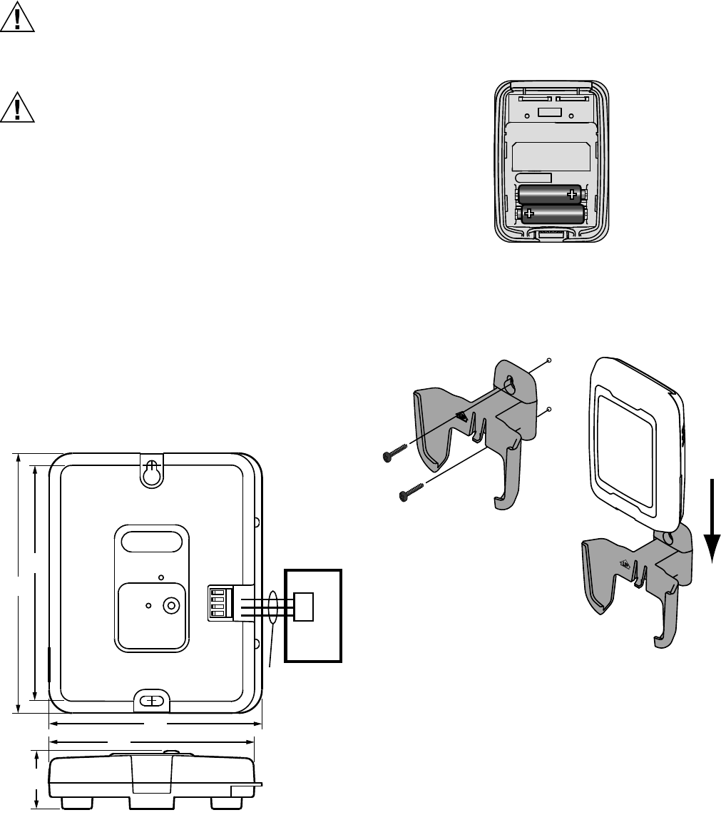
Fig. 1. W8735ER Wireless Outdoor Reset Module wiring
diagram.
C7089R INSTALLATION
Mount Outdoor Sensor
Before installing the C7089 sensor, make sure 2 AA (lithium
preferred) batteries are inserted. See Fig. 2.
Fig. 2. Battery Installation
1. Mount the sensor bracket on a vertical wall. at least 6
inches below any overhang. Choose a location pro-
tected from direct sunlight. See Fig. 3.
Fig. 3. Mounting the Sensor Bracket and Sensor
2. Mount the sensor bracket in the selected spot.
3. Once the sensor is bound to the W8735ER (see SEN-
SOR BINDING), place the sensor in the bracket, facing
away from the wall.
M33912
5-9/16
(141)
5-1/32
(128)
1-1/4
(32)
4-9/16
(116)
4-13/32
(112)
X
3
2
1
W8735ER1000
Wireless
Outdoor Reset Module
POWER
WIRELESS SETUP
CONNECTED
CONNECT
FLASHING: CONNECTING TO REMOTE DEVICE(S)
GREEN: CONNECTED TO REMOTE DEVICES(S)
RED: REMOTE DEVICE(S) NOT COMMUNICATING
EnviraCOM
BUS
3
2
1
EnviraCOM
ENABLED
CONTROL
M32937
M28491
M28849A
W8735ER WIRELESS OUTDOOR RESET MODULE
366-1202—01
Sensor Binding
The C7089R Outdoor Sensor must be bound with the
W8735ER Wireless Outdoor Reset Module in order for
communication between the two controls to be established.
When the W8735ER Wireless Outdoor Temperature Module
is powered but not bound to a sensor, the POWER LED will be
ON (green) and the CONNECTED LED will be OFF.
1. Remove the cover from the C7089R to expose the
CONNECT button.
2. Press the CONNECT button on the W8735ER until the
CONNECTED LED flashes green (1 blink/second) after
approximately five seconds of flashing red. If the sensor
is not bound within the next 15 minutes the W8735ER
times out and the CONNECTED LED will turn OFF.
3. While the CONNECTED LED flashes green on the
W8735ER, press the CONNECT button on the C7089R
sensor.
4. The CONNECTED LED will start to blink fast (4 blinks/
second).
NOTE: If flashing doesn’t speed up to 4 blinks/second,
the sensor and the W8735ER have not bound.
Repeat step 4. If binding is not successful during
a 15 minutes period, the W8735ER will time
out. Repeat steps 2 through 4. Make sure the
W8735ER and the sensor are positioned at least
3 feet apart during the binding process.
5. Once the flashing rate goes back to 1 blink/second,
press the CONNECT button on the W8735ER to end
the binding process.
6. Once the C7089R sensor and the W8735ER bind, the
CONNECTED LED on the W8735ER will be ON solid
(green).
7. Place sensor cover back on the sensor and return the
sensor to the bracket. See Fig. 3.
NOTE: Pressing the CONNECT button on either the
W8735ER or wireless sensor for 15 seconds or
more will result in the unbinding of the wireless
sensor and deactivation of the OTC functionality.
To rebind the sensor to the W8735ER follow
steps 1-7 in this section.
NOTES:
— If the W8735ER is bound to a sensor but the sen-
sor signal is lost, the CONNECTED LED will be
ON (red).
— Once the sensor is bound to the W8735ER and
the module is connected to the EnviraCOM com-
munication bus as described in the WIRING sec-
tion of this document, hold the sensor where you
intend to install it and check for the outdoor tem-
perature to be displayed on the combustion con-
trol. If the outdoor temperature is not displayed,
change the positioning of the sensor.
— If the W8735ER is not successfully bound to
C7089R within five minutes of power up, the
W8735ER will generate a missing sensor alarm.
See Table 6 for a complete listing of EnviraCOM
alarms and trobuleshooting guide.
W8735ER WIRELESS OUTDOOR RESET MODULE
66-1202—01 4
OPERATION
General
The W8735ER Wireless Outdoor Reset Module is a device
which when connected to an AquaReset enabled Electronic
Aquastat, Integrated Boiler Control (IBC) or SOLA control via
the EnviraCOM™ communication bus, enhances the available
control features to include Outdoor Temperature Reset, a
stepped Boost function as well as Warm Weather Shutdown
to provide increased boiler efficiency while servicing the heat
demand. Set-up of the Outdoor Setback curve as well as the
Boost function is done using the 3-digit/3-button display on the
L7224/L7248 Aquastat (see L7224 Installation Instructions
Form Number 69-1720 and/or Form Number 68-0281 for
more information). For the IBC setup see Form Number 66-
1203 Installation Instructions for more information. For SOLA,
set-up of the reset curve is done using the S7910 or S7999
display (See Form Numbers 65-0315, 66-1175, and 68-0295
for more information.)
Adjusting Aquastat and IBC Settings
To discourage unauthorized/unintentional changing of
Aquastat and IBC settings, a procedure to enter the
ADJUSTMENT mode is required. To enter the ADJUSTMENT
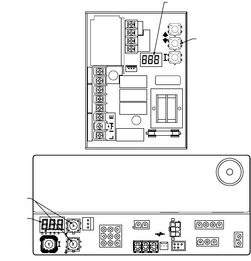
mode, press the UP, DOWN, and I buttons (See Fig. 4)
simultaneously for three seconds. Next, press the I button until
the feature requiring adjustment is displayed then use the
arrow up/down buttons to set the parameter value (See Table
4). After 60 seconds without any button inputs, the controller
will automatically return to the normal display mode.
Fig. 4. Location of L7224/L7248 and S936X 3-digit display and buttons.
Outdoor Reset
The Outdoor Reset feature adjusts the target boiler
temperature to a point below its local high limit setting and
above the boiler's condensation temperature by using the
EnviraCOM communication bus to directly adjust the Aquastat
set-point. Should a call for Domestic Hot Water be detected,
the boiler temperature is commanded to return to the High
Limit setting, ensuring a hot water supply is available. When
the Domestic Hot Water demand is met, the Outdoor Reset
feature is once again enabled. See Table 1 and Fig. 5.
Application and Settings Pointers
The energy savings concept behind Outdoor Reset is to
minimize the energy in the boiler that is lost during the off
cycle. This is accomplished by maintaining the boiler
temperature as low as possible and/or running the boiler for
longer periods of time. Although considerable energy savings
exists, the boiler is only one part of the system that includes
thermostats, other controls, and radiation. To maximize
savings while avoiding call-backs due to uncomfortable
homeowners, care must be taken when adjusting the control
parameters. Listed below are operation and adjustment
pointers. See Fig. 5.
Low Boiler Temperature: This is the minimum temperature
at which the boiler is designed to operate. Setting this too low
during warmer periods may result in condensation in the boiler
and reduce boiler life. Typically this setting is 130 °F (54 °C)
for gas boilers and 140 °F (60 °C) for oil boilers and is
adjusted to be maintained at the high outdoor temperature
setting. Some new cast iron boilers are designed to operate at
lower temperatures. Consult the manufactures' specifications.
Low Outdoor Temperature: As the outdoor temperature
decreases, the boiler temperature must increase to provide
more heat to the space. The Low Outdoor Temperature
C1
B1
ZC
L2
LINE
C2
ZR
L1
B2
T
T3
2
1
THREE-DIGIT
DISPLAY
BUTTONS
M33913
GND
BUTTONS
THREE-DIGIT
DISPLAY
W8735ER WIRELESS OUTDOOR RESET MODULE
566-1202—01
(design temperature) is the point at which the boiler should be
set to its high limit setting. Setting the boiler temperature too
low during the coldest periods will result in the inability to keep
up with heat demand. This is the critical setting in avoiding
call-backs.
High Outdoor Temperature: This is the outdoor temperature
for which the Low Boiler Temperature is set. This is the
parameter that most impacts energy savings. Setting the High
Outdoor Temperature too high results in less energy savings
as the boiler may run at a higher temperature during warmer
weather than necessary to maintain comfort in the space.
Setting this parameter too low will result in too narrow a range
for the control to be adjusting boiler temperature. In most
cases the default of 40 °F (4.4 °C) is fine.
NOTE: In many cases these parameters will not need to
be adjusted as their default values are designed
to accommodate mid-Atlantic and lower New
England areas.
CAUTION
Possible Equipment Damage
When enabling the Outdoor Reset function, be sure to
refer to the boiler OEM’s instructions for the lowest
return water setting to avoid condensation in the heat
exchanger, which can result in equipment damage.
1Minimum values, Maximum values and Default High Limit
settings shown are for the L7224U and the S9361 IBC. Val-
ues may change for other Aquastats and IBCs. Check the
specific Aquastat and/or IBC Installation Instruction manual
for more information on default settings.
Boost
If heat demand is not met within a certain time period while
the boiler is in setback mode (following the Outdoor Reset
curve), a Boost Period is invoked where the boiler set point is
increased by a value called the Boost Step. Each time the
Boost Period elapses and heat demand is not satisfied, the
boiler set-point is again increased by the Boost Step, up to the
maximum setting provided by the High Limit setting (see Table
2 and Fig. 5). Boost is reset when the heat demand is satisfied
(local or remote call for heating has ended). Simply reaching
the boiler set-point does not reset the Boost. Continuous
Boost calls may be an indication of a poorly set Outdoor Reset
Curve for the environment or faulty equipment. For the
Aquastat, a Boost warning will be indicated on the 3-digit
Aquastat display if Boost is required on 60 consecutive cycles.
See Table 5.
For the Aquastat, the Boost Period can be set from OFF to a
range of 5 minutes to 30 minutes, adjustable in 1 minute
increments. The default setting is 10 minutes. The Boost Step
can be set from Off to a range of 5 F (-15 C) to 20 F (-7 C).
For the IBC, the Boost Period is fixed at 30 minutes and the
Boost Step is fixed at 5 °F. See Table 2.
1 For the IBC, both the Boost Period and Boost Step are fixed
parameters and can not be adjusted.
Warm Weather Shutdown - Aquastat
The Warm Weather Shutdown feature causes a “Warm Start”
boiler to shut down when the outdoor temperature exceeds a
specified value. Warm Start boilers maintain a minimum
temperature by setting the Low Limit on the Aquastat. If
enabled this features cancels the Low Limit setting when the
outdoor temperature exceeds a specified value.
CAUTION
Zone Panel Settings
In applications with zoning panels having a priority
zone for domestic hot water: Disable the warm
weather shutdown feature on the Aquastat.
The Warm Weather Shutdown feature can be set from OFF to
a range of 40 °F (4.4°C) to 70 °F (21 °C), adjustable in 10
degree increments. The default setting is OFF. See Table 3.
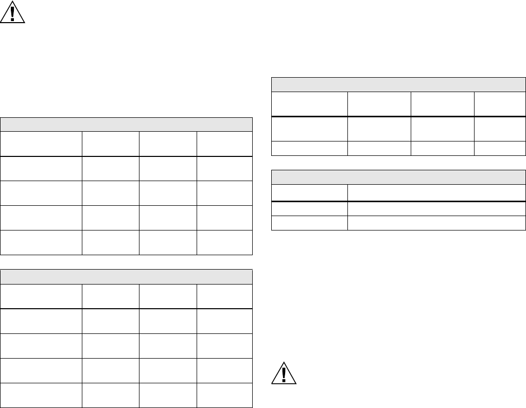
Table 1. Outdoor Reset Curve Settings and Defaults.1
Aquastat
Parameter
Minimum
value
Maximum
value Default
High Limit 130 °F
(54 °C)
240 °F
(116 °C)
180 °F
(82 °C)
Minimum Outdoor
Temperature
-40 °F
(-40 °C)
40 °F
(4.4 °C)
0°F
(-18 °C)
Minimum Boiler
temperature
80 °F
(27 °C)
180 °F
(82 °C)
130 °F
(54 °C)
Maximum Outdoor
Temperature
30 °F
(-1 °C)
70 °F
(21 °C)
40 °F
(4.4 °C)
IBC
Parameter
Minimum
value
Maximum
value Default
High Limit 130 °F
(54 °C)
220 °F
(104 °C)
180 °F
(82 °C)
Minimum Outdoor
Temperature
-40 °F
(-40 °C)
40 °F
(4.4 °C)
0°F
(-18 °C)
Minimum Boiler
temperature
130 °F
(54 °C)
150 °F
(56 °C)
140 °F
(60 °C)
Maximum Outdoor
Temperature
40°F
(12.7 °C)
70 °F
(21 °C)
40°F
(12.7°C)
Table 2. Boost Settings and Defaults.
Aquastat
Parameter name
Minimum
value
Maximum
Value Default
Boost Period 5 minutes
(or Off)
30 minutes 10 minutes
Boost Step 5 F (or Off) 20 F10F
IBC
Parameter name Value1
Boost Period 30 minutes
Boost Step 5 F (or Off)
W8735ER WIRELESS OUTDOOR RESET MODULE
66-1202—01 6
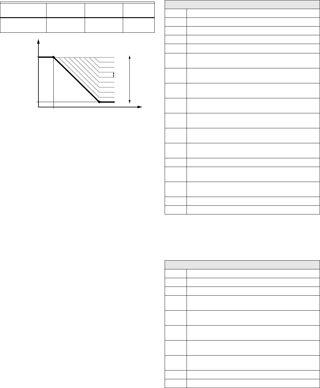
Fig. 5. Outdoor temperature setback curve with boost.
As Outdoor Temp reaches the Warm Weather Shutdown set-
point (if enabled), the boiler is kept from cycling and will only
service DHW demands if the Aquastat Zr terminal is
configured for Domestic Hot Water request. See Table 4 on
page 6.
Table 3. Warm Weather Shutdown Settings and Defaults.
Parameter name
Minimum
value
Maximum
Value Default
Warm Weather
Shutdown
40 F (or Off) 70 FOff
HIGH LIMIT
BOILER
TEMPERATURE
M29557
MINIMUM BOILER
TEMPERATURE
MINIMUM
OUTDOOR
TEMPERATURE
MAXIMUM
OUTDOOR
TEMPERATURE
OUTDOOR
TEMPERATURE
BOOST
STEP
BOOST
Table 4. Programming Parameters.
Aquastat
HL_ High Limit.
Hdf High Limit Differential.
LL**_ Low Limit.
Ldf Low Limit Differential.
ELL*** ZR input configured as External Low Limit (ON/OFF)
duu ZR input configured as external Domestic Hot Water
(DHW) request (ON/OFF)
ASC Anti Short Cycle Timeout (seconds); “OFF” is
disabled.
otL Outdoor Temperature Low (minimum) parameter for
the outdoor reset curve (F or C)*
otH Outdoor Temperature High (maximum) parameter for
outdoor reset curve (F or C)*
btL Boiler Temperature Low (minimum) parameter for
outdoor reset curve*
bP Boost Period (minutes). “OFF” is displayed if Boost is
inactive*
bS Boost step (F or C) shown only if Boost is active
(bP=ON)*
UUS Warm Weather Shutdown Temperature (F or C)*
tPL** Thermal Purging Limit Temperature (F or C),
“OFF” if disabled.
tPt** Thermal Purging Time Delay (minutes), shown only
if tPL is enabled
PC Pump Cycling (ON/OFF)
F-C Temperature units (F or C)
*Settings available for adjustment on the 3-digit Aquastat
display only when the “Outdoor Reset Module” is installed.
**Not displayed when connected to an L7248 Aquastat
Control.
***Only displayed when connected to an L7248L Aquastat
Control.
IBC
HL_ High Limit.
Hdf High Limit Differential.
Or_ Pump Overrun Time
otL Outdoor Temperature Low (minimum) parameter for
the outdoor reset curve (F or C)
otH Outdoor Temperature High (maximum) parameter for
outdoor reset curve (F or C)
btL Boiler Temperature Low (minimum) parameter for
outdoor reset curve
tPL Thermal purging minimal temperature (Parameter is
available only if outdoor temperature is invalid)
tPt Maximal Thermal Purge time (Parameter is available
only if outdoor temperature is invalid)
rSt Reset Lockout
F-C Temperature units (F or C)

W8735ER WIRELESS OUTDOOR RESET MODULE
766-1202—01
WIRELESS OUTDOOR RESET MODULE ALARMS AND
TROUBLESHOOTING
The W8735ER Wireless Outdoor Reset Module’s enhanced diagnostics provides information alerting of deteriorating boiler
efficiency or if the system is not running optimally. Outdoor reset-related errors can be displayed on diagnostic tools and displays.
Errors are also displayed on the Aquastat's 3-digit display. See Table 5 for available Outdoor reset-related error codes.
aWarnings are generated to enunciate the system is not operating optimally, but the Aquastat is still operating and maintaining
boiler temperature. In the instance where an Outdoor Reset Module is used, the warnings may indicate a reset curve setting
error one or more features is not running optimally, and the Aquastat is reverting to default settings or has stopped running the
Outdoor Reset algorithms. The warnings are cleared when the issue(s) is resolved.
NOTE: Aquastat alarms reset automatically once the alarm condition has been resolved. Alarms can also be reset by
cycling power if the alarm condition is no longer present.
Table 5. Aquastat Outdoor Reset Related Error Codes.
Error
Code Cause/Action
EnviraCOM
Alarm
Err 9aWarning: Outdoor Reset System failure; communication to Outdoor Reset Module lost, Outdoor
Reset Module failure, multiple outdoor temperature sensors detected on the bus, or outdoor
temperature sensor failure. Check EnviraCOM wiring (1, 2, 3), check sensor wiring.
50, 53, 149
Err 10aWarning: Boost Failure; Boost Mode active at least once per cycle for the last 60 consecutive
cycles. Check Outdoor Reset curve settings.
150
Err 11aDHW Module Sensor failure.
Warning: DHW System failure; communication to DHW Module lost, DHW Module failure, or
temperature sensor failure. Check EnviraCOM wiring (1, 2, 3), check sensor wiring.
146, 147, 148
Table 6. EnviraCOM Outdoor Reset Alarms and Troubleshooting.
Alarm Desription
EnviraCOM
Alarm Troubleshooting
Duplicate Outdoor Temp Alarm Present 50 Only one outdoor sensor (wired/wireless) is allowed.
Ensure no other outdoor sensors is connected.
Outdoor Temp Sensor Low Battery Alert 156 Replace sensor batteries
Outdoor Sensor Missing/Failure 53 Outdoor sensor failure. Replace sensor.
Missing Outdoor Temp Sensor 149 Module not bound within 5 minutes of power-up or lost once
enrolled. Check batteries

W8735ER WIRELESS OUTDOOR RESET MODULE
Automation and Control Solutions
Honeywell International Inc.
1985 Douglas Drive North
Golden Valley, MN 55422
customer.honeywell.com
® U.S. Registered Trademark
© 2012 Honeywell International Inc.
66-1202—01 M.S. 08-12
Printed in United States
Regulatory information
FCC Compliance Statement (Part 15.19) (USA only)
This device complies with Part 15 of the FCC Rules.
Operation is subject to the following two conditions:
1 This device may not cause harmful interference, and
2 This device must accept any interference received, includ-
ing interference that may cause undesired operation.
FCC Warning (Part 15.21) (USA only)
Changes or modifications not expressly approved by the party
responsible for compliance could void the user’s authority to
operate the equipment.
FCC Interference Statement (Part 15.105 (b)) (USA only)
This equipment has been tested and found to comply with the
limits for a Class B digital device, pursuant to Part 15 of the
FCC Rules. These limits are designed to provide reasonable
protection against harmful interference in a residential
installation. This equipment generates uses and can radiate
radio frequency energy and, if not installed and used in
accordance with the instructions, may cause harmful
interference to radio communications. However, there is no
guarantee that interference will not occur in a particular
installation. If this equipment does cause harmful interference
to radio or television reception, which can be determined by
turning the equipment off and on, the user is encouraged to
try to correct the interference by one of the following
measures:
• Reorient or relocate the receiving antenna.
• Increase the separation between the equipment and
receiver.
• Connect the equipment into an outlet on a circuit different
from that to which the receiver is connected.
• Consult the dealer or an experienced radio/TV technician
for help.
Wireless adapter
To comply with FCC and Industry Canada RF exposure limits
for general population/ uncontrolled exposure, the antenna(s)
used for these transmitters must be installed to provide a
separation distance of at least 20 cm from all persons and
must not be co-located or operating in conjunction with any
other antenna or transmitter.
Section 7.1.5 of RSS-GEN
Operation is subject to the following two conditions:
1 this device may not cause interference, and
2 this device must accept any interference, including interfer-
ence that may cause undesired operation of the device.
Information sur Ia reglementation
Adaptateur sans fll
Pour être conformes aux limites d’exposition aux
radiofréquences établies par la FCC et Industrie Canada pour
le grand public/l’exposition non contrôlée, la ou les antennes
employées par le transmetteur doivent être installées sur une
structure extérieure permanente à au moins 20 cm de
distance de toute personne et ne peuvent être situées au
même endroit qu’une autre antenne ou un autre transmetteur
ou fonctionner conjointement avec une autre antenne ou un
autre transmetteur.
Industrie Canada Alinéa 7.1.5 de CNR-GEN
Le fonctionnement de ce système est assorti aux deux
conditions suivantes :
1 L’appareil ne peut causer d’interférences nuisibles, et
2 L’appareil doit accepter les interférences reçues, y compris
celles qui pourraient nuire à son fonctionnement.