Adt Security Services Safewatch Plus Enterpreneur Systems Users Manual
Safewatch Plus Enterpreneur Security Systems to the manual 8efc3f3f-81a2-4c22-ab78-85c13a5c8d5d
2015-02-02
: Adt-Security-Services Adt-Security-Services-Safewatch-Plus-Enterpreneur-Security-Systems-Users-Manual-413042 adt-security-services-safewatch-plus-enterpreneur-security-systems-users-manual-413042 adt-security-services pdf
Open the PDF directly: View PDF ![]() .
.
Page Count: 1
ADT-1090-INT 7/25/00 3:12 PM Page 1

ADT-1090-INT 7/25/00 3:12 PM Page 2

Table of Contents
*
System Reference .................................................
2
Operating Your System
.........................................
3
ARMING
.......................................................................................
3
Arming The System Prior To Leaving
.....................................
3
Arming The System Without Leaving
..................................... 3
System
Will
Not Arm (Ready Light Off)
.................................. 4
DISARMING
...................................................................................... 5
Disarming Upon Entering The Premises
................................ 5
ALARM CONDITIONS
...................................................................... 6
What To Do If An Alarm Occurs
.............................................. 6
False Alarms
............................................................................. 6
THE EMERGENCY KEYPAD PANIC ALARMS
.............................. 7
Emergency Alarm Activation
................................................... 7
Resetting The Emergency Alarm
............................................
7
SPECIAL FEATURES
...................................................................... 8
Chime Mode
.............................................................................. 8
Force Arming
............................................................................ 8
Bypassing Zones
......................................................................
9
Key Switch Operation
............................................................ 10
Access
..................................................................................... 10
The Reset Key
.............................
..”
........................................ 10
Remote Programming
............................................................ 10
Audible Zone Testing
.............................................................
11
FIRE DETECTION
.......................................................................... 12
What To Do If The Fire Alarm Sounds
..................................
12
Fire
Supervlsoryflrouble
(Resetting Smoke Detectors).
..
..12
Emergency Evacuation Plan
...............................
13
Fire
Prevention and Escape
.................................................. 14
Fire Protection
........................................................................ 15
Glossary
...............................................................
17
Index .....................................................................
18
1
Zone Identification Card
Space is provided for
recording the areas of
protection which are
;“““““““““‘““““““““’
:
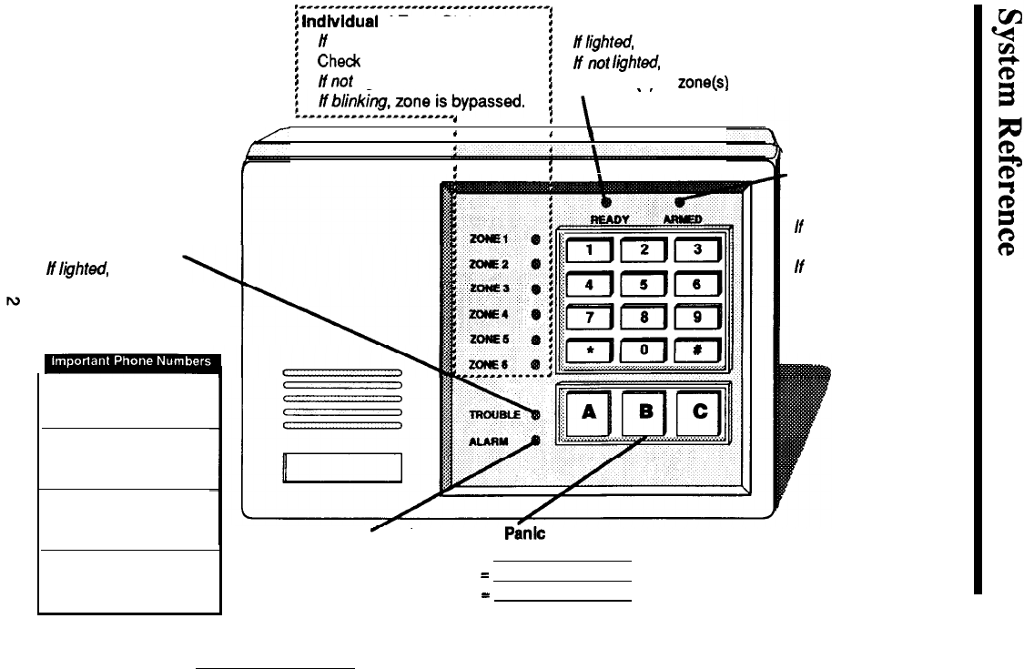
lndlvldual
Zone Status
i
Ready status
If
lighted, zone is not secure.
i
;
/flight&
the system is ready to be armed.
Chedc
doors, windows, etc.
If
not
Iighted,
one or more zones are faulted.
i
!
H
not
lighted, zone is secure.
i
,
Indicator(s) of zonekl at fault will be lighted.
assigned to each zone.
i___~bll~~~~~_~~~~_~_bypassed.
!.
,.
,
Depending upon the
,
I
installation, this card pulls
1
,
\
out from the left or right
!
,
I
\
Armed Status
If lighted, the system is
armed.
condition exists.
Contact your security
representative.
side of the control station.
Trouble Indicator
/f
/ighted,
a trouble
Alarm Co:
Police:
Fire:
If
not lighted, the
system is disarmed.
If
b/inking, time is being
provided to exit the
building, after which the
system will be armed.
Alarm Indicator
If lighted, an alarm
has occurred.
Emergency
Panic
Keys
PANIC A =
PANIC B
=
PANIC C
=
NOTE: The
Emergency Panic Keys may
or may not be active. Check with your
security representative for details.
Operating Your System
ARMING
Before the control can be armed, all of the intrusion zones must be secure as
indicated by the green READY indicator. If the READY indicator is off, one or
more zones are faulted. The indicator(s) corresponding to the faulted zone(s) will
light. Use the pull out zone I.D. card on the control station to determine the areas of
protection which are assigned to each of the six (6) zones, thencheckthe appropriate
doors and windows to see that they are closed.
1.
Verify that the
READY
indicator is on.
2. Enter your User Code.
3.
The control station will begin beeping and the red ARMED indicator will blink
to indicate that arming will take place after the exit time expires. (The ARMED
indicator will light steady after the system arms).
4. Leave the building immediately.
The control is programmed with an exit delay time which allows a specific amount
of time to leave through any delay defined intrusion detection zone without causing
an alarm. Be sure that you have been informed on routes to enter and exit from
without causing an alarm. If too much time is taken to exit, the beeping tone will
change to a steady tone, indicating the start of entry delay. Disarm the control and
start over to avoid a false alarm.
Your security system is divided into two areas of protection:
1.
2.
PERIMETER-Thefirstlineofdefense. Consistsofoneormorezoneswhich
detect intrusion through doors and windows.
INTERIOR
-
The
backup or second line of defense. Consists of one or more
zones that detect intruders that have already entered the building. Interior
detection devices usually consist of motion detection devices, interior door
contacts, and under carpet sensors, designed to surprise
the
intruder.
prior to arming the control, you may first choose to turn off the interior protection,
allowing free movement within the building when armed.
3
;I
Turning Off the
lnterlor
Zones and Entrance Delay
Control station key 4 may be used to turn the interior zones off prior to arming. This
will allow the system to alarm instantly if the entrance door is opened, while armed.
1.
Press the 4 key and hold for three seconds.
2.
When interior defined zones are turned off, the corresponding Zone indicators
will flash. The flashing will stop 30 seconds after the system is armed.
3.
Arm the system by entering your User Code.
Note: Upon disarming, the interior zones automatlcally w-enable
unless
your Installer has altered
this
feature through programming.
Q
Automatic Interior Off/Delay Off
Your
system may have been programmed to automatically turn the interior zones
off if you arm and do not leave the premises before the exit delay time expires. The
entrance delay may also
be
programmed to automatically turn off at this time. When
the system is disarmed, the interior and delay
wilI
return to their normal on or off
state. See your security representative for details.
Q
Two
Digit
Arming
Your system may have been programmed with an abbreviated arming feature.
When this feature is enabled, only the first two digits of your User Code will be
required to arm the system
and
perform other features. Disarming however, will still
require the entire code sequence.
If the READY indicator is off, one or more detection devices such as a door or
window has been left open. The system cannot be armed. One or more of the six
ZONE indicators will also be lighted indicating the area of protection that is at fault.
Use the pull out zone I.D. card on
the
control station to define the area of protection
assigned to each zone.
NOTE:
If
an attempt Is made to arm the system
with
the READY light off,
a three second error tone wilt be
emltted
to alert you that the system did
not arm.
4

DISARMING
Your system is programmed with one or more entrance delay zones which allow
time to enter the premises without causing an alarm. Each delay door may be
programmed with a different entry time. Be sure to check with your installer.
Note: If your system has the “Interior Follower” feature enabled, all
interior designated zones automatically become delay zones whenever
you first enter through a delay zone. This allows you to walk In front of
motion detectors on the way to the control station after you enter.
1.
After entering the premises through a delay zone, the control station will sound
a continuous tone to remind you to disarm the system.
CAUTION: If the ALARM
indicator
is lighted, an alarm has occurred.
Leave the premises immediately and go to the nearest phone to contact
the appropriate
authorities. Do not procede into the premises.
2.
Enter your User Code.
3.
The red armed light should turn off indicating that the system is disarmed.
Testing the Burglar and Fire Alarm Audibles
UL listed burglar and fire alarm systems which have separate audible
sounding devices require a weekly test. Notify the Central Station or the
appropriate authorities before and after conducting the test. Use the
following procedures.
Burglar
alarm
1.
Arm the system by following the instructions on the preceding pages.
2.
Upon expiration of the exit delay open a non-delayed door, window, or
motion detector. The sounding device will activate. To reset, follow the
instructions on disarming the system.
Fire
alarm
1.
Follow the procedure
for
activation of the auxiliary alarms as outlined on
page
7
of this manual.
5
ALARM CONDITIONS
Whenever an alarm occurs, the ALARM indicator will light, the audible alarm will
sound (if applicable), and the control
wilI
communicate with the central station (if
this option was purchased).
NOTE: If upon
returning to the
premises it
1s
discovered that an alarm has
occurred,
DO
NOT ENTER THE PREMISES.
Leave
immediately and go to
the nearest phone and contact the appropriate authorities.
0
To reset the alarm:
1.
2.
Enter your User Code to reset the alarm.
The ALARM indicator will remain lighted.
If the alarm was activated through one of the six “hardwire” zones, the corre-
sponding ZONE indicator(s) will also be lighted, identifying the specific area
that was violated. Use the zone I.D. card to determine the area of protection
which corresponds to each zone.
If the alarm was activated manually by pressing one of the emergency keys, no
zone indicators will be lighted.
Press the
“
*
”
key to extinguish the ALARM indicator after determining the
type of alarm that occurred and area of protection involved.
A history of the alarm condition will be stored in the control’s memory and may be
.
recalled at any time. See “Special
Fkatures”
for more information.
If for any reason a false alarm occurs, perform the following steps:
1.
2.
3.
4.
Enter your User Code.
The armed light should turn off.
Notify the appropriate authorities of the alarm immediately.
Press the
“
*
”
key to extinguish the ALARM light. Use the zone I.D. card to
detemine the area of protection assigned to each zone.
6
THE EMERGENCY KEYPAD PANIC ALARMS
Your system may have been purchased with up to three emergency keypad panic
alarms. These may be used to activate an alarm in the event of a Fire, Hold-up, or
other emergency condition, as programmed by your installer. Each alarm is
activated by pressing the appropriate emergency panic key (located below the
numeric keys). Each alarm may be audible or silent. It may also be programmed
to report
the
condition to
a
central monitoring station. Check with your security rep-
resentative to determine the characteristics of your system.
Each of the three emergency panic keys (from left to right: A, B, and C) can initiate
a specific type of alarm as programmed and labeled by your installer.
To activate an Emergency Alarm:
1. Press the appropriate emergency panic key. The Emergency Alarm will
activate.
NOTE: Your
lnstalter
may have
progmmmed
the panic zones to ignore
momentaty
key presses
and
to
activate
only
by pressing and
holding
pressed
for three seconds (or pressing at least twice
within
three sec-
onds).
Checkwlthyoutsecurttyrepresentatlveforthespeclflccharacter-
istlcs
of your system
When an Emergency Alarm is activated, the ALARM indicator will be lighted
(unless your installer has programmed the alarm for silent or no control station in-
dication). To reset
the
alann:
1. Enter your User Code. Pressing the
“
*
”
key will extinguish the ALARM
indicator, if lighted.
Ahistoryofthelastalarmwillbestoredinthecontrol’smemoryandmayberecalled
if desired. (See “Special Features”).
7
SPECIAL FEATURES
The CHIME mode allows audible monitoring of zones while
the
system is
disarmed. When the CHIME mode is active, the control station sounder will beep
whenever a perimeter burglar defined zone (door, window, etc.) indicator is opened.
For example, the CHIME feature will cause the control station to beep two times
whenever the front door has been opened. Many businesses use this type of signal
to announce that a customer has entered. In a residential application, the CHIME
is useful for monitoring opening of doors by children.
0
1.
2.
3.
cl
1.
To Turn CHIME On
The
system must be disarmed.
Press the “6” key and hold for three seconds. The control station will beep three
times to signify that the CHIME has been turned on.
The control station will now beep two times when any burglar zone is
opened.
Note: The CHIME feature does not annunciate
lntertor
zones.
To Turn The CHIME
Off
Press the
“6”
key and hold for three seconds. The control station will beep two
times to signify that the CHIME has been turned off.
Your system may be programmed for quick arming even with one or more zones
faulted. In this condition, when an attempt is made to arm the system with faulted
zones (READY light off), the control station will emit a three second error tone,
indicating that the system refused to arm. If a second attempt to arm is made within
eight seconds after the tone quits, all faulted zones will automatically be bypassed
and the system will Force Arm. Depending upon how your system was
pro
grammed at the time of installation, force armed zones will either be permanently
bypassed until disarming or may return to operation when or if they become
operable.
8
The bypass key
(#)
is used to bypass selected zones in your system. A bypassed zone
will NOT be capable of activating an alarm as it is temporarily removed from your
system. Bypassing (also referred to as shunting) is most commonly used to allow
free movement of an area (zone or group of zones) while arming the rest of the
system or to temporarily remove a zone or zones that require
service
allowing
partial
use of the system until repaired. When zones are bypassed, the corresponding
ZONE indicators flash to indicate that they have been removed from operation. The
flashing will cease 30 seconds after the
exit
delay expires when the system is armed.
cl
1.
2.
3.
4.
cl
1.
2.
3.
cl
1.
2.
cl
1.
2.
3.
Note: When zones are bypassed, security Is
compromlsed.
Do not
instruct temporary users on use of the bypass feature.
To Bypass A Zone
The system must be disarmed.
Press the BYPASS key
(#)
then enter the number of the zone (l-6) to be
bypassed.
The corresponding ZONE indicators (l-6) will blink to indicate zones that have
been bypassed. The blinking will cease 30 seconds after the system is
armed
and
the exit delay expires.
Repeat steps 2 and 3 to bypass other zones.
To Cancel A Zone Bypass
The system must be disarmed.
Press the BYPASS key
(#)
followed by the number of the zone (l-6) to be
restored to service.
The ZONE indicator of the previously bypassed zone will stop blinking.
To Cancel All Zone Bypasses
Press the
BYPASS key
(#)
followed by key
“
9
“.
All ZONE indicators will stop flashing. The zones are returned to operation.
To Bypass All Faulted Zones Simultaneously
(Not
available
in U.L. Listed Systems).
The system must be disarmed.
Press the BYPASS key
(#)
then press the
“
0
”
key.
All faulted zones will simultaneously be bypassed. The corresponding ZONE
indicators (l-6) will blink to indicate zones that have been bypassed. The
blinking will cease 30 seconds after the system is armed.
9
Your system may utilize a conventional key switch for arming and disarming the
system. Arming and disarming with a key switch is performed as follows:
cl
1.
2.
3.
0
1.
2.
Arming
Verify that the BEADY light is on.
Insert your key into the key switch and turn. Hold for one second and release.
The
red ARMED light will blink during the exit delay cycle and then light steady
when the system arms.
Disarming
Insert your key into the key switch and turn. Hold for one second and release.
The red
ARMED
light will go out indicating that the system is disarmed.
m
U.L. Note: The control is not listed to Standard U.L.294 Access Control Units
If your system was purchased with the ACCESS feature, the control station can be
used to switch other devices on and off or as a timed switch. This feature is most
commonly used to activate an electric door release or switch lights on and off.
Consult your security representative for more information.
The
“
*
”
key may be used to:
DSilence the control station sounder and the audible output during Auxiliary “A”
(Fire) and Auxiliary “C” (Emergency) alarms.
Cl
Silence the control station sounder during Burglar alarms.
Ct
Exit the audible test mode.
NOTE:
Pressing
the
*
*
*’
key does not
resef
alarms or cancel reporting
to the central statlon.
Your system is capable of being serviced remotely from the alarm company’s
service office providing that the system is set up for
Remote Programming. The
system provides a means of verifying that this feature is enabled. See your security
representative for more information.
10

Programming
Certain features of your system are programmable through the control station. The
programming mode is entered by pressing key 9 and holding for three seconds, then
entering the Master User Code. Other programming functions may be possible that
are not detailed in this section. Consult your security representative for a list of the
user programmable features of your system.
WARNING:
Do
not attempt to program the system unless you have been
properly trained on programming procedures and you are sure that you
fully understand
thlsopwatlon.
USER CODES
Your system may be programmed to accept up to five regular User Codes and one
Muster User Code.
Each code
may be comprised of any four digit sequence. (Do
not program 1234 or 1111 as User Codes). Codes may be added, deleted, or changed
as necessary.
The Master User Code (code 1) performs all of the User Code functions plus allows
access to the programming mode.
User Code 6 may be programmed as a Temporary User Code with a limited number
of valid uses, after which it becomes inoperable.
This code may be assigned to a
maintenance person, maid, or anyone who you would like to be able to arm and
disarm the system for a selected number of times without having to reveal your
regular code.
A
Determine your desired new User Code or Master User Code sequence. If you
make an error while programming, press the
“
*
”
key five times and start over from
step 1.
WARNING: Pressing the
“
#
”
or
l4
*
”
key while programmlng a code may
result In Improper code operation, therefore you MUST return to step 1
when an error Is made.
0
1.
2.
3.
4.
5.
To Change A
User
Code
The
system must be disarmed.
Press key 9 and hold for three seconds. The control station will beep three times.
Enter the Master User Code. The control station will beep two times. The
READY and ARMED indicators will blink alternately and the other eight
indicators will blink repeatedly when the programming mode is successfully
entered (see note
+
on page
C).
Press a key (Z-6) which corresponds to the User Code you wish to program, or
press key 1 to change the Master User Code, then press the
“
#
”
key. For
example, press 1, then
#
to change the Master User Code, or 4 then
#
to program
User Code 4, etc. The control station will beep three times to signify acceptance.
Enter the desired new 4 digit code sequence. After the fourth digit is entered,
the control station will emit one short beep followed by one long beep then the
system will exit the programming mode automatically. To program another
code, return to step 2.
1.
2.
3.
4.
5.
6.
The system must be disarmed.
Press key 9 and hold for three seconds. The control station will beep three times.
Enter the Master User Code. The control station will beep two times. The
READY and ARMED indicators will blink alternately and the other eight
indicators will blink in sequence with each other when the programming mode
is successfully entered (see note
$).
Press
key
1,
then key 0, then # which instructs the control that you wish to delete
a code. The control station will beep three times to signify acceptance.
Enter the number of the code (l-6) to be deleted.
The code is now deleted. The system will automatically exit the programming
mode.
B

An optional feature of your system allows you to assign a certain number of valid
uses to User Code 6. After the code has been used the programmed amount of times,
it automatically becomes disabled. This code may be assigned to a maintenance
person, a maid, or anyone who you would like to be able to arm and disarm the
system for a selected number of times without having to give out your regular code.
After the uses have expired,
the
code will cease to function. It can be re-enabled by
programming in another number indicating how many times
that
it can be used. It
will not be necessary to re-program the actual code unless changing the code itself
is desired.
1.
2.
3.
4.
5.
6.
7.
8.
9.
The system must be disarmed.
Press key 9 and hold for three seconds. The control station will beep three times.
Enter the Master User Code. The control station will beep two times. The
READY and ARMED indicators will blink alternately and the other eight
indicators will blink in sequence with each other when the programming mode
is successfully entered (see note
*).
Press key 6, then
#
to instruct the control
that
you wish to program the desired
code sequence for User Code 6. The control station will beep three times.
Enter the desired four digit code sequence. After the fourth digit is entered, the
control station will emit one short beep followed by one long beep then the
system will exit the programming mode automatically.
Repeat step 2 to re-enter
the
programming mode.
Press keys 7 plus # to instruct the control that you wish to program the number
of valid uses for User Code 6. The control station will beep two times.
Enter the number of uses desired,
1
-
255, then press the
“
* “key. The control
station will beep two times.
Press the
“
*
”
key twice to exit the programming mode.
Note:
The temporary code may perform ail oft
he
functfons of your regular
User Codes. Only the Master User
Code
(Coda
1) will
permit entry into the
programming mode of operation. Remote Ptogrammlng Is not avaltable
In
U.L. Listed Systems.
+
NOTE REGARDING REMOTE PROGRAMMING:
If the ALARM indicator lightssteady after entering the programming mode,
your Installer has enabled the Remote Programming optlon. This feature
enables the installing company (or someone assigned by them) to re-
motely
service
and control your system.
C
Notes
The TEST mode commands the control station to beep continuously and light the
corresponding zone indicator, each time a zone is violated. The zone indicator of
each tested zone will remain lighted while each succeeding zone is tested. Testing
can be performed only while the system is disarmed. Testing the system should be
performed in both ELECTRICAL
ROWER
AC ON and STANDBY BATTERY
modes. Your neighbors’ understanding and cooperation is very important. When
you are away from your residence (or commercial
business),neighbors
play an
important role. Advise them that you have a security system and ask them to notify
the proper authorities if your system is sounding. The burglar alarm typically has
a pulsing bell and a fire alarm has a steady horn sound. If the battery fuse lead is
opened, call your security representative for service.
Note: A
lighted zone indicator means
thst
at least one sensor of that
particular zone
h8S
been tested. It does not
necessarfly
mean that
all
sensors of that zone were tested.
W
is recommended that you test your
system on 8 weekly
basis.
1.
2.
3.
8.
9.
The system must be disarmed.
Use the zone I.D. card to determine the area of protection which corresponds to
each zone.
To simplify testing, all zones should first be secured (READY light ON). If it
is not possible to secure all zones prior to beginning the walk test mode, please
note that the control station will beep continuously as a result of the non-secure
zones. This will eliminate the advantages of the audible walk test mode,
although the zone indicator lights may still be relied upon for testing.
Press key 8 and hold for three seconds. The control station will beep three times
to signify entry into the TEST mode.
Violate a detection zone (open a door, window, etc.). The control station will
beep continuously and the indicator of the corresponding zone will light.
Secure the zone (close the door, window, etc.). The control station beeping will
cease.
The interior detection devices will also cause the control station to beep if
entering those protected areas when testing unless the INTERIOR is first turned
OFF. You may also want to walk test motion detection devices to check whether
the pattern is covering the areas of concern.
Begin at step five to test the remaining sensors.
Press the
“
*
”
key when finished testing.
Note:
Your
system
should be
rsgutarly
tested at
lsast
ones
par
week
to
insure proper operation.
Cantact
your
security
representative for
com-
plate instructions on regular system
malrttenence
and testing
prooe-
dures.lf
the wall mounted transformer which powers the system Is
re-
moved for any reason, test the system to see If the standby
battery
Is
adequately powertng
thesystem.
Re+onnect
the transformer, secure to
the
wallplate
with the restraining
teb
machine
screw,
and
test the system
agaln
to
8ssure
It
la
recelvlng
AC power.
11
FIRE DETECTION
Your system may or may not include fire detection, depending upon what options
were purchased, and the local codes and regulations for your area. Fire alarm
systems are active 24 hours a day and cannot be turned off.
A!!
fire systems require
regular testing and maintenance. Common household dust build-up in smoke
detectors can cause them to false alarm or fail in a time of need. Consult your
security representative for a scheduled maintenance program.
1.
2.
3.
4.
5.
6.
The red ALARM indicator will be lighted and the alarm sounder will be
sounding steadily. The ZONE indicator(s) corresponding to the violated Fire
Zone(s) will also be lighted. If the alarm was activated manually through the
control station emergency panic zone, no ZONE indicators will be lighted.
Press the
“
*
”
key to silence the control station and the audible alarm.
Notify the
alarm
monitoring
service or the proper authorities immediately
if the alarm was unintentional.
The
red ALARM light will remain on.
To clear the alarm, enter a valid User Code.
If the TROUBLE indicator lights, a Fire Supervisory/Trouble condition may
exist. Consult your Security Representative to define the trouble condition.
Many smoke detectors “latch on” and illuminate a built in indicator when triggered.
This feature allows you to determine which detector caused the alarm. If a smoke
detector remains latched after resetting a fiie alarm activation, the yellow TROUBLE
indicator will be lighted.
1.
2.
Check all smoke detectors for the presence of a latched condition to determine
which detector triggered the alarm. If all detectors appear normal, a wire may
be broken or shorted. Call for service.
Press Key 7 and hold for three seconds. The system will attempt to reset the
smoke detectors. If the smoke detector(s) did not reset, the control station will
continue to indicate the TROUBLE condition.
Call your security representa-
tive for service.
12
Emergency Evacuation Plan
Preparation and education are of prime importance in the prevention of fire. An
emergency evacuation
plan
should be established BEFORE an emergency situation
arises. Your system may or may not contain
fire
detection and notification
equipment. Be sure to have your installer explain and that you fully understand
exactly what your system consists of. Use the following steps in establishing an
emergency evacuation plan:
1.
2.
3.
4.
5.
Evaluate all possible escape routes from your home and draw a floor plan.
Select two exit escape routes from each
mm.
Provide emergency escape ladders for rooms above the first floor. Check
the ladders to be sure that they will reach the ground.
Draw a rough sketch of your escape plan so that everyone is familiar with it.
Practice your escape plan to assure that everyone knows what they have to
do in an emergency situation.
6.
Establish a meeting place outside where your family is to report.
7.
Advise the local fire authority if you have installed a fire alarm system.
D
Discuss
the
followlng
wlth all
residents:
1.
2.
3.
Familiarity with alarm signals.
Status of bedroom doors.
Testing of door during a fire and use of alternate escape routes if HOT to
touch.
4.
Crawling and holding breath techniques during a fire.
5.
Escape FAST, DO NOT STOP for packing.
6.
Emphasize that no one is to return to a burning building.
13
The purpose of heat and smoke detectors is to detect a fire in its earliest stages and
sound an alarm, giving occupants more time to exit the premises before smoke
reaches a dangerous level.
Cl KNOW FIRE HAZARDS
No
detection device can protect life in all situations; therefore, safeguards should
be taken to avoid such potentially dangerous situations as smoking in bed, leaving
children home alone, and cleaning with flammable liquids such as gasoline.
The best fire protection is minimizing
fire
hazards through proper storage of
materials and good housekeeping practices. Careless use of combustible materials
andelectricalappliances or overloading of electrical outlets are major causes of fire.
Explosive and fast burning materials must be eliminated from the home.
0
IN CASE OF FIRE
Leave
immediately! Do not stop to pack or search for valuables. In heavy smoke,
hold your breath and stay low-crawl
if
necessary.
The clearest air usually is at the
floor. If you have to go through
a
closed door, carefully feel the door and door knob
to see if undue heat is present. If relatively cool, brace your foot against the bottom
ofthedoorwithyourhipagainstthemiddle,andonehandagainstthetopedge.Open
slightly. If there is arush of hot air, slam the door quickly and latch it. Unvented fire
will build up considerable pressure. Be sure that all the household realizes this
danger.
Use your neighbors
phone
or street fire alarm box. The job of extinguishing the
fire
should be left to the professionals. Too many unforeseen things can occur when
inexperienced people try to extinguish a fue.
0
BE PREPARED
Perform
fire
drills regularly. Use them to assure recognition of an alarm signal. For
your protection, simulate different circumstances (smoke the hall, living room,
etc.).Then
haveeveryonereacttothesituation.
Draw
a floorplanandshow
twoexits
from each room. It is important that children be instructed carefully. Their tendency
is to hide in a crisis.
It is imperative that one meeting place outside the home be established. You should
insist that everyone meet there during an alarm. This will eliminate the tragedy of
someone re-entering the house for a missing member who is
actually
safe.
If you have small children and/or invalids residing in your household, you can help
yourfnedepartmentby placingdecalson bedroom windows. Mostfiredepartments
supply the decals.
Become familiar with the distinctive sounds of your
Fire
alarm and Burglar alarm
signals.
14
0
Smoke Detector Location
Smoke detectors should be installed in accordance with theNational FireProtection
Association
(NFPA)
Standard 74.
The following is from NFPA 74:
Smoke detectors shall
be
installed
outside
of
each
separate sleeping area in the immediate vicinity of the bedrooms and on each
additional story of the family living unit including basement and excluding crawl
spaces and unfinishedattics (see illustration below). For family living units with one
or more split levels (i.e., adjacent levels with with less than one full story separation
between levels), a smoke detector required by the above shall suffice for an adjacent
lower level, including basements.
EXCEPTION:
Where there is an intervening door between one level and the
adjacent lower level, a smoke detector shall be installed on the lower level.
Ceiling mounted smoke alarms should be located in the center of the room or hall,
not less than 4 inches from any wall. When the detector is mounted on a wall, the
top of the detector should be 4 to 12 inches from the ceiling.
Do not install smoke alarms where normal ambient temperatures are above
lOOoF
(37.8”C),
or below
40’F
(4’C).
Also, do not locate smoke detectors in front of air conditioners, heating registers,
or other locations where normal air circulation will keep smoke from entering the
detector.
Heat from a fire rises to the ceiling, spreads out across the ceiling surface and begins
to bank down from the ceiling. The comer where the ceiling and wall meet is an air
space into which heat has difficulty in penetrating. In most
fires,
this ‘dead’ air space
measures about 4 inches (O.lm) along the ceiling from the comer and 4 inches
(O.lm) down the
wall
as shown in the illustration below. Heat or smoke detectors
should not be placed in this ‘dead’ air space.” (See illustration on next page).
15
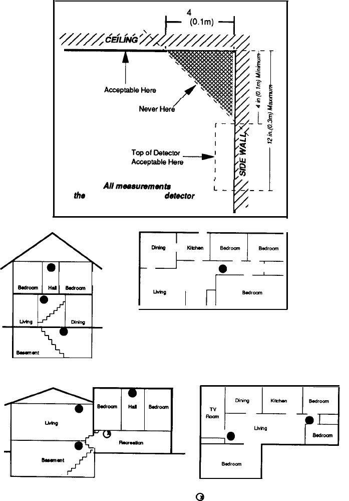
Smoke Detector Placement
4
inches
@lm)
-_I
NOTE:
Allmae~~mmennts
are to
the
closest edge of the
dote&or
A Smoke Detector should
be located on each story.
A Smoke Detector should be located
between the sleeping area and the rest
of the family living unit.
l
Indicates required smoke detector @
Indicates smoke detector is optional
if door is not provided between living
and recreational rooms.
16

Glossary
Alarm Memory: A history of the alarm that last occurred.
Arm: To turn the intrusion detection system on.
Bypass: To temporarily remove a zone from operation. To Shunt a zone.
Control Panel: The main system electronics housed in a metal enclosure.
Control Station: The remote station used to enter instructions to the control panel
such as to arm, disarm amd bypass. Also called a keypad.
Delay Zone: Zone which allows a programmable amount of time to enter and
disarm the system without activating an alarm. Also provides an exit time to leave
the premises after arming. “Delay” may be assigned to any number of zones.
Disarm: To turn the intrusion detection system off.
Entrance Delay: Time permitted to enter the armed premises through a delay
defined zone.
Faulted:
A detection area which is not secure such as a protected door or window
which has been left open causing the control to loose its “Ready” status..
Force Arm: To override. To force the system to arm when one or more zones are
not ready.
Hardwire
Zones: The six areas of protection referred to as Zones
1
. ...6 on the
control station.
Indicator Lights: The ten lights
(LEDs)
on the control station.
Interior:
The backup or second line of defense. Consists of one or more zones that
detect intruders that have already entered the building. Interior detection devices
usually consist of motion detection devices, interior door contacts, and under
carpet sensors, designed to surprise the intruder.
Interior Follower Feature: Converts interior zones to delay zones upon entry
through a delay door. Interior follower provides passage through interior detection
zones to the control station in order to disarm the system.
Keypad: A generic term for the control station.
17

ADT-1090-INT 7/25/00 3:13 PM Page 12

ADT-1090-INT 7/25/00 3:13 PM Page 12

Notes
20
FCC COMPLIANCE
This equipment ganerates and uses radio frequency energy and
lf
nU installed and used properly, that
!a.
In strict
accordance
with
the rtwnufacturer’s instructions, may
catae
interference to radio and teledslon raceptlon.
lt
has been type
tested and found to corrpiy with the
llmks
for a Class
B
corrputlng devtce In
acwtdance
with the specHications of Subpart
J or pan 15 of FCC rules. which are designed to pmvlde reasonable pmtectlon against such Interference in a residential
Installatfon.
However, there
Is
no guarantee that Interference
will
na
ocarr
In a particular Installation.
k
this equipment does
uwse
interference to radio or televtsbn receptbn. which can be determlned by turning the equipment off and on, the user
Is
encouraged
10
try to correct the Interference by one or more of the following measures:
1.
Reorient the TV or radio antenna
2.
Reiocate or move lhe alarm control away from the receiver.
3.
Plug the transformer for the alarm control Into a different outlet so that the
receiver
and the
alarm
are on different branch
circuits.
4.
lf
necessary, the user should consult the afarm deafer or an experienced radiotelevision technlctan for additional
suggestions.
The user may find the following booklet prepared by the Federal Communications Commission hebful: “How To Identify
and Resoive
RadioTV
Interference
Probbms:
This booklet
ts
available from the U.S. Government Printing
Offkx.
Washington, DC 20402 stock
1004~CCC-00345-f.
ALL RIGHTS RESERVED
No part of
this
pubiicatbn may be reproduced, stored In a retrieval system or transrwtted In any form, or by any means
-
electronic. mechanical, photocopying, recording. or otherwise without the prbr written permission of Aritech Corp. The
material in this publication is for information purposes and subject to change without notice. Arkech Corp assumes no
responsibility for any errors which may appear in
this
publicadion.
Printed in U.S.A.

MOOSE
Sentrol,
Inc
resen~es
the rtght
to change specifmtmns
wthout
notice
tJ1991
Sentrol.
Inc
