Adtran 1248 Users Manual
1248 5967e40c-9b71-1494-7db8-c0a37d8d3d18 ADTRAN Network Card 1248 User Guide |
2015-01-24
: Adtran Adtran-1248-Users-Manual-345039 adtran-1248-users-manual-345039 adtran pdf
Open the PDF directly: View PDF ![]() .
.
Page Count: 234 [warning: Documents this large are best viewed by clicking the View PDF Link!]
- Total Access 1248 Octal T1 IMA DSLAM Installation and Maintenance Practice
- Front Matter
- Contents
- Section 1, Introduction
- Section 2, Application Guidelines
- Section 3, Installation
- Section 4, Provisioning Defaults
- Section 5, User Interface
- Introduction
- System Management
- Logging on to the Total Access 1248
- Menu Structure
- Menu Navigation
- Menu Tree
- Menu Descriptions
- Configuration Screen
- ATM Circuit Management Menu
- System Management Menu
- Password Control Menu
- Mode Selection and Current IP Settings Menu
- Test IP Address Menu
- Time/Date Adjust Menu
- Current Baud Rate Menu
- TFTP Configuration Storage/Retrieval Screen
- SNMP/TL1 Configuration Menu
- Code Download Method Menu
- Restore Factory Defaults Menu
- Reset System Menu
- Self Test Menu
- External Alarms Menu
- Expansion Menu
- Network Port Menu
- DSL Menus
- System Alarm Log Screen
- System Event Log Screen
- Contact Information Screen
- TL1 Mode Screen
- Section 6, Maintenance
- Section 7, Specifications
- Appendix A, Warranty

Total Access 1248
Octal T1 IMA DSLAM
Installation and Maintenance Practice
Document Number: 61179641L4-5B
CLEI Number: VAMBD00A_ _
September 2007
1
2
3
4
T1/E1
5
6
7
8
®

Total Access 1248 Octal T1 IMA DSLAM Installation and Maintenance Practice
ii 61179641L4-5B
Front Matter
Trademarks
Any brand names and product names included in this document are trademarks, registered
trademarks, or trade names of their respective holders.
To the Holder of the Document
The contents of this document are current as of the date of publication. ADTRAN® reserves the
right to change the contents without prior notice.
In no event will ADTRAN be liable for any special, incidental, or consequential damages or
for commercial losses even if ADTRAN has been advised thereof as a result of issue of this
document.
901 Explorer Boulevard
P.O. Box 140000
Huntsville, AL 35814-4000
(256) 963-8000
©2007 ADTRAN, Inc.
All Rights Reserved.
®

61179641L4-5B iii
Revision History
Conventions
The following typographical conventions are used in this document:
This font indicates a cross-reference link.
This font indicates screen menus, fields, and parameters.
THIS FONT indicates keyboard keys (ENTER, ESC, ALT). Keys that are to be pressed simultaneously
are shown with a plus sign (ALT+X indicates that the ALT key and X key should be pressed at the
same time).
This font indicates references to other documentation and is also used for emphasis.
This font indicates on-screen messages and prompts.
This font indicates text to be typed exactly as shown.
This font indicates silkscreen labels or other system label items.
This font is used for strong emphasis.
NOTE
Notes inform the user of additional, but essential, information or
features.
CAUTION
Cautions inform the user of potential damage, malfunction, or dis-
ruption to equipment, software, or environment.
WARNING
Warnings inform the user of potential bodily pain, injury, or death.
Revision Date Description
ASeptember
2005
Initial release. Software revision B02
BSeptember
2007
This is the second release of this document. This revision updates
the software to Version B03.06.01.

Total Access 1248 Octal T1 IMA DSLAM Installation and Maintenance Practice
iv 61179641L4-5B
Training
ADTRAN offers training courses on our products. These courses include overviews on product
features and functions while covering applications of ADTRAN product lines. ADTRAN
provides a variety of training options, including customized training and courses taught at our
facilities or at customer sites.
For enquiries concerning training, contact ADTRAN:
Training Phone: 800-615-1176, ext. 6996
Training Fax: 256-963-6217
Training Email: training@adtran.com

61179641L4-5B v
Contents
Section 1
Introduction . . . . . . . . . . . . . . . . . . . . . . . . . . . . . . . . . . . . . . . . . . . . . . . . . . . . . . . . . . . . . . . . . . . . 1-1
General . . . . . . . . . . . . . . . . . . . . . . . . . . . . . . . . . . . . . . . . . . . . . . . . . . . . . . . . . . . . . . . . . . . . . . . . . . . . . 1-1
Description. . . . . . . . . . . . . . . . . . . . . . . . . . . . . . . . . . . . . . . . . . . . . . . . . . . . . . . . . . . . . . . . . . . . . . . . . . 1-2
Features . . . . . . . . . . . . . . . . . . . . . . . . . . . . . . . . . . . . . . . . . . . . . . . . . . . . . . . . . . . . . . . . . . . . . . . . . 1-2
Front Panel LEDs . . . . . . . . . . . . . . . . . . . . . . . . . . . . . . . . . . . . . . . . . . . . . . . . . . . . . . . . . . . . . . . . . . 1-3
Compliance . . . . . . . . . . . . . . . . . . . . . . . . . . . . . . . . . . . . . . . . . . . . . . . . . . . . . . . . . . . . . . . . . . . . . . 1-4
Section 2
Application Guidelines . . . . . . . . . . . . . . . . . . . . . . . . . . . . . . . . . . . . . . . . . . . . . . . . . . . . . . . . . . . 2-1
Introduction . . . . . . . . . . . . . . . . . . . . . . . . . . . . . . . . . . . . . . . . . . . . . . . . . . . . . . . . . . . . . . . . . . . . . . . . . 2-1
Expansion . . . . . . . . . . . . . . . . . . . . . . . . . . . . . . . . . . . . . . . . . . . . . . . . . . . . . . . . . . . . . . . . . . . . . . . . . . 2-2
Section 3
Installation . . . . . . . . . . . . . . . . . . . . . . . . . . . . . . . . . . . . . . . . . . . . . . . . . . . . . . . . . . . . . . . . . . . . . 3-1
Introduction . . . . . . . . . . . . . . . . . . . . . . . . . . . . . . . . . . . . . . . . . . . . . . . . . . . . . . . . . . . . . . . . . . . . . . . . . 3-1
Shipping Contents . . . . . . . . . . . . . . . . . . . . . . . . . . . . . . . . . . . . . . . . . . . . . . . . . . . . . . . . . . . . . . . . . 3-2
Required Tools . . . . . . . . . . . . . . . . . . . . . . . . . . . . . . . . . . . . . . . . . . . . . . . . . . . . . . . . . . . . . . . . . . . . 3-2
Installation Prerequisites . . . . . . . . . . . . . . . . . . . . . . . . . . . . . . . . . . . . . . . . . . . . . . . . . . . . . . . . . . . . . . 3-3
Installation Steps. . . . . . . . . . . . . . . . . . . . . . . . . . . . . . . . . . . . . . . . . . . . . . . . . . . . . . . . . . . . . . . . . . . . . 3-4
Mounting the Total Access 1248 . . . . . . . . . . . . . . . . . . . . . . . . . . . . . . . . . . . . . . . . . . . . . . . . . . . . . . 3-5
Flush-mount . . . . . . . . . . . . . . . . . . . . . . . . . . . . . . . . . . . . . . . . . . . . . . . . . . . . . . . . . . . . . . . . . . . 3-6
Mid-mount . . . . . . . . . . . . . . . . . . . . . . . . . . . . . . . . . . . . . . . . . . . . . . . . . . . . . . . . . . . . . . . . . . . . 3-7
Ground Connection . . . . . . . . . . . . . . . . . . . . . . . . . . . . . . . . . . . . . . . . . . . . . . . . . . . . . . . . . . . . . . . . 3-8
Power Connection . . . . . . . . . . . . . . . . . . . . . . . . . . . . . . . . . . . . . . . . . . . . . . . . . . . . . . . . . . . . . . . . . 3-9
Fans/Fan Filter . . . . . . . . . . . . . . . . . . . . . . . . . . . . . . . . . . . . . . . . . . . . . . . . . . . . . . . . . . . . . . . . . . . 3-10
Ethernet Connection . . . . . . . . . . . . . . . . . . . . . . . . . . . . . . . . . . . . . . . . . . . . . . . . . . . . . . . . . . . . . . 3-11
Alarm Connections . . . . . . . . . . . . . . . . . . . . . . . . . . . . . . . . . . . . . . . . . . . . . . . . . . . . . . . . . . . . . . . . 3-12
Network Connections . . . . . . . . . . . . . . . . . . . . . . . . . . . . . . . . . . . . . . . . . . . . . . . . . . . . . . . . . . . . . . 3-13
ADSL2+ Plus POTS Connections . . . . . . . . . . . . . . . . . . . . . . . . . . . . . . . . . . . . . . . . . . . . . . . . . . . . 3-14
POTS Interface . . . . . . . . . . . . . . . . . . . . . . . . . . . . . . . . . . . . . . . . . . . . . . . . . . . . . . . . . . . . . . . 3-14
ADSL2+ Plus POTS Interface . . . . . . . . . . . . . . . . . . . . . . . . . . . . . . . . . . . . . . . . . . . . . . . . . . . . 3-14
POTS Connection . . . . . . . . . . . . . . . . . . . . . . . . . . . . . . . . . . . . . . . . . . . . . . . . . . . . . . . . . . . . . 3-15
Customer Connections (ADSL+POTS) . . . . . . . . . . . . . . . . . . . . . . . . . . . . . . . . . . . . . . . . . . . . . 3-15
Total Access 1200F Conversion . . . . . . . . . . . . . . . . . . . . . . . . . . . . . . . . . . . . . . . . . . . . . . . . . . . . . . . 3-17
Quick Turn-up Steps . . . . . . . . . . . . . . . . . . . . . . . . . . . . . . . . . . . . . . . . . . . . . . . . . . . . . . . . . . . . . . . . . 3-19

Total Access 1248 Octal T1 IMA DSLAM Installation and Maintenance Practice
vi 61179641L4-5B
Section 4
Provisioning Defaults . . . . . . . . . . . . . . . . . . . . . . . . . . . . . . . . . . . . . . . . . . . . . . . . . . . . . . . . . . . . 4-1
Introduction . . . . . . . . . . . . . . . . . . . . . . . . . . . . . . . . . . . . . . . . . . . . . . . . . . . . . . . . . . . . . . . . . . . . . . . . . 4-1
Section 5
User Interface. . . . . . . . . . . . . . . . . . . . . . . . . . . . . . . . . . . . . . . . . . . . . . . . . . . . . . . . . . . . . . . . . . . 5-1
Introduction . . . . . . . . . . . . . . . . . . . . . . . . . . . . . . . . . . . . . . . . . . . . . . . . . . . . . . . . . . . . . . . . . . . . . . . . . 5-1
System Management. . . . . . . . . . . . . . . . . . . . . . . . . . . . . . . . . . . . . . . . . . . . . . . . . . . . . . . . . . . . . . . . . . 5-1
Craft Interface . . . . . . . . . . . . . . . . . . . . . . . . . . . . . . . . . . . . . . . . . . . . . . . . . . . . . . . . . . . . . . . . . . . . 5-1
Inband Management Interface . . . . . . . . . . . . . . . . . . . . . . . . . . . . . . . . . . . . . . . . . . . . . . . . . . . . . . . . 5-2
Logging on to the Total Access 1248 . . . . . . . . . . . . . . . . . . . . . . . . . . . . . . . . . . . . . . . . . . . . . . . . . . . . 5-3
Menu Structure . . . . . . . . . . . . . . . . . . . . . . . . . . . . . . . . . . . . . . . . . . . . . . . . . . . . . . . . . . . . . . . . . . . . . . 5-4
Menu . . . . . . . . . . . . . . . . . . . . . . . . . . . . . . . . . . . . . . . . . . . . . . . . . . . . . . . . . . . . . . . . . . . . . . . . . . . 5-4
Screen . . . . . . . . . . . . . . . . . . . . . . . . . . . . . . . . . . . . . . . . . . . . . . . . . . . . . . . . . . . . . . . . . . . . . . . . . . 5-4
Menu Navigation . . . . . . . . . . . . . . . . . . . . . . . . . . . . . . . . . . . . . . . . . . . . . . . . . . . . . . . . . . . . . . . . . . . . . 5-5
Hot Keys . . . . . . . . . . . . . . . . . . . . . . . . . . . . . . . . . . . . . . . . . . . . . . . . . . . . . . . . . . . . . . . . . . . . . . . . . 5-5
Menu Tree. . . . . . . . . . . . . . . . . . . . . . . . . . . . . . . . . . . . . . . . . . . . . . . . . . . . . . . . . . . . . . . . . . . . . . . . . . . 5-9
Menu Descriptions . . . . . . . . . . . . . . . . . . . . . . . . . . . . . . . . . . . . . . . . . . . . . . . . . . . . . . . . . . . . . . . . . . 5-15
Configuration Screen . . . . . . . . . . . . . . . . . . . . . . . . . . . . . . . . . . . . . . . . . . . . . . . . . . . . . . . . . . . . . . 5-17
ATM Circuit Management Menu . . . . . . . . . . . . . . . . . . . . . . . . . . . . . . . . . . . . . . . . . . . . . . . . . . . . . 5-18
PVC/PVP Management Menu . . . . . . . . . . . . . . . . . . . . . . . . . . . . . . . . . . . . . . . . . . . . . . . . . . . . 5-19
Create a New PVC/PVP Screen . . . . . . . . . . . . . . . . . . . . . . . . . . . . . . . . . . . . . . . . . . . . . . . 5-21
Delete an Existing PVC/PVP Screen . . . . . . . . . . . . . . . . . . . . . . . . . . . . . . . . . . . . . . . . . . . 5-23
Modify an Existing PVC/PVP Screen . . . . . . . . . . . . . . . . . . . . . . . . . . . . . . . . . . . . . . . . . . . 5-24
Current ATM OAM Statistics Menu . . . . . . . . . . . . . . . . . . . . . . . . . . . . . . . . . . . . . . . . . . . . . 5-26
OAM Loopback Test Menu . . . . . . . . . . . . . . . . . . . . . . . . . . . . . . . . . . . . . . . . . . . . . . . . 5-28
Current ATM PVC Performance Menu . . . . . . . . . . . . . . . . . . . . . . . . . . . . . . . . . . . . . . . . . . 5-31
ATM Quick Provisioning Menu . . . . . . . . . . . . . . . . . . . . . . . . . . . . . . . . . . . . . . . . . . . . . . . . 5-33
ATM Traffic Parameter Defaults Screen . . . . . . . . . . . . . . . . . . . . . . . . . . . . . . . . . . . . . . . . . . . . 5-35
Restore ATM Factory Defaults Menu . . . . . . . . . . . . . . . . . . . . . . . . . . . . . . . . . . . . . . . . . . . . . . 5-36
ATM Performance Monitoring Mode Menu . . . . . . . . . . . . . . . . . . . . . . . . . . . . . . . . . . . . . . . . . . 5-38
ATM Performance Monitoring Status Screen . . . . . . . . . . . . . . . . . . . . . . . . . . . . . . . . . . . . . 5-40
ATM Port Cell Count Summary Screen . . . . . . . . . . . . . . . . . . . . . . . . . . . . . . . . . . . . . . . . . 5-42
Clear All PM for All Ports Menu . . . . . . . . . . . . . . . . . . . . . . . . . . . . . . . . . . . . . . . . . . . . . . . . 5-43
ATM OAM Settings Menu . . . . . . . . . . . . . . . . . . . . . . . . . . . . . . . . . . . . . . . . . . . . . . . . . . . . . . . 5-44
Inband OAM Loopback Test Menu . . . . . . . . . . . . . . . . . . . . . . . . . . . . . . . . . . . . . . . . . . . . . 5-45
System Management Menu . . . . . . . . . . . . . . . . . . . . . . . . . . . . . . . . . . . . . . . . . . . . . . . . . . . . . . . . . 5-47
Password Control Menu . . . . . . . . . . . . . . . . . . . . . . . . . . . . . . . . . . . . . . . . . . . . . . . . . . . . . . . . 5-49
Password Control Levels Screen . . . . . . . . . . . . . . . . . . . . . . . . . . . . . . . . . . . . . . . . . . . . . . 5-50
Allow SNMP Security Management . . . . . . . . . . . . . . . . . . . . . . . . . . . . . . . . . . . . . . . . . . . . 5-51
Set Menus Idle Logout Time . . . . . . . . . . . . . . . . . . . . . . . . . . . . . . . . . . . . . . . . . . . . . . . . . . 5-51
Set TL1 Menus Idle Logout Time . . . . . . . . . . . . . . . . . . . . . . . . . . . . . . . . . . . . . . . . . . . . . . 5-51
Set TL1 Inband Idle Logout Time . . . . . . . . . . . . . . . . . . . . . . . . . . . . . . . . . . . . . . . . . . . . . . 5-51
Restore Default Passwords . . . . . . . . . . . . . . . . . . . . . . . . . . . . . . . . . . . . . . . . . . . . . . . . . . . 5-51
Mode Selection and Current IP Settings Menu . . . . . . . . . . . . . . . . . . . . . . . . . . . . . . . . . . . . . . . 5-52
Static IP Settings - for IP over ATM Menu. . . . . . . . . . . . . . . . . . . . . . . . . . . . . . . . . . . . . 5-54
Restore IP Factory Defaults Menu . . . . . . . . . . . . . . . . . . . . . . . . . . . . . . . . . . . . . . . 5-56
Dynamic IP Settings - for IP over ATM Menu . . . . . . . . . . . . . . . . . . . . . . . . . . . . . . . . . . 5-57
Restore IP Factory Defaults Menu . . . . . . . . . . . . . . . . . . . . . . . . . . . . . . . . . . . . . . . 5-59
Static IP Settings - for IP over Ethernet Menu . . . . . . . . . . . . . . . . . . . . . . . . . . . . . . . . . . 5-60
Restore IP Factory Defaults Menu . . . . . . . . . . . . . . . . . . . . . . . . . . . . . . . . . . . . . . . 5-62
Dynamic IP Settings - for IP over Ethernet Menu . . . . . . . . . . . . . . . . . . . . . . . . . . . . . . . 5-63
Restore IP Factory Defaults Menu . . . . . . . . . . . . . . . . . . . . . . . . . . . . . . . . . . . . . . . 5-65

Contents
61179641L4-5B vii
Test IP Address Menu . . . . . . . . . . . . . . . . . . . . . . . . . . . . . . . . . . . . . . . . . . . . . . . . . . . . . . . . . . 5-66
Time/Date Adjust Menu . . . . . . . . . . . . . . . . . . . . . . . . . . . . . . . . . . . . . . . . . . . . . . . . . . . . . . . . . 5-67
Current Baud Rate Menu . . . . . . . . . . . . . . . . . . . . . . . . . . . . . . . . . . . . . . . . . . . . . . . . . . . . . . . . 5-68
TFTP Configuration Storage/Retrieval Screen . . . . . . . . . . . . . . . . . . . . . . . . . . . . . . . . . . . . . . . 5-69
SNMP/TL1 Configuration Menu . . . . . . . . . . . . . . . . . . . . . . . . . . . . . . . . . . . . . . . . . . . . . . . . . . . 5-71
SNMP Contact Information Menu . . . . . . . . . . . . . . . . . . . . . . . . . . . . . . . . . . . . . . . . . . . . . . 5-72
SNMP Community Names Menu . . . . . . . . . . . . . . . . . . . . . . . . . . . . . . . . . . . . . . . . . . . . . . 5-73
SNMP Trap Hosts Menu . . . . . . . . . . . . . . . . . . . . . . . . . . . . . . . . . . . . . . . . . . . . . . . . . . . . . 5-75
Code Download Method Menu . . . . . . . . . . . . . . . . . . . . . . . . . . . . . . . . . . . . . . . . . . . . . . . . . . . 5-77
Y-Modem Menu . . . . . . . . . . . . . . . . . . . . . . . . . . . . . . . . . . . . . . . . . . . . . . . . . . . . . . . . . . . . 5-78
TFTP Download Screen . . . . . . . . . . . . . . . . . . . . . . . . . . . . . . . . . . . . . . . . . . . . . . . . . . . . . 5-79
Auto Upgrade Configuration (AUC) Status Menu . . . . . . . . . . . . . . . . . . . . . . . . . . . . . . . . . . 5-81
Restore Factory Defaults Menu . . . . . . . . . . . . . . . . . . . . . . . . . . . . . . . . . . . . . . . . . . . . . . . . . . . 5-84
Reset System Menu . . . . . . . . . . . . . . . . . . . . . . . . . . . . . . . . . . . . . . . . . . . . . . . . . . . . . . . . . . . 5-85
Self Test Menu . . . . . . . . . . . . . . . . . . . . . . . . . . . . . . . . . . . . . . . . . . . . . . . . . . . . . . . . . . . . . . . 5-86
External Alarms Menu . . . . . . . . . . . . . . . . . . . . . . . . . . . . . . . . . . . . . . . . . . . . . . . . . . . . . . . . . . 5-88
External Alarm Severity Menu . . . . . . . . . . . . . . . . . . . . . . . . . . . . . . . . . . . . . . . . . . . . . . . . . 5-89
Expansion Menu . . . . . . . . . . . . . . . . . . . . . . . . . . . . . . . . . . . . . . . . . . . . . . . . . . . . . . . . . . . . . . 5-90
Network Port Menu . . . . . . . . . . . . . . . . . . . . . . . . . . . . . . . . . . . . . . . . . . . . . . . . . . . . . . . . . . . . . . . 5-91
T1 Main Menu . . . . . . . . . . . . . . . . . . . . . . . . . . . . . . . . . . . . . . . . . . . . . . . . . . . . . . . . . . . . . . . . 5-92
T1 Provisioning Menu . . . . . . . . . . . . . . . . . . . . . . . . . . . . . . . . . . . . . . . . . . . . . . . . . . . . . . . 5-94
T1 Status Menu . . . . . . . . . . . . . . . . . . . . . . . . . . . . . . . . . . . . . . . . . . . . . . . . . . . . . . . . . . . . 5-96
T1 PM Main Menu . . . . . . . . . . . . . . . . . . . . . . . . . . . . . . . . . . . . . . . . . . . . . . . . . . . . . . . . . . 5-98
T1 Performance Monitoring Status Screen . . . . . . . . . . . . . . . . . . . . . . . . . . . . . . . . . . . . 5-99
T1 Test Menu . . . . . . . . . . . . . . . . . . . . . . . . . . . . . . . . . . . . . . . . . . . . . . . . . . . . . . . . . . . . 5-101
Restore T1 Factory Defaults Menu . . . . . . . . . . . . . . . . . . . . . . . . . . . . . . . . . . . . . . . . . . . . 5-102
E1 Main Menu . . . . . . . . . . . . . . . . . . . . . . . . . . . . . . . . . . . . . . . . . . . . . . . . . . . . . . . . . . . . . . . 5-103
E1 Provisioning Menu . . . . . . . . . . . . . . . . . . . . . . . . . . . . . . . . . . . . . . . . . . . . . . . . . . . . . . 5-104
E1 Status Menu . . . . . . . . . . . . . . . . . . . . . . . . . . . . . . . . . . . . . . . . . . . . . . . . . . . . . . . . . . . 5-105
E1 PM Main Menu . . . . . . . . . . . . . . . . . . . . . . . . . . . . . . . . . . . . . . . . . . . . . . . . . . . . . . . . . 5-106
E1 Performance Monitoring Status Screen . . . . . . . . . . . . . . . . . . . . . . . . . . . . . . . . . . . . . . 5-107
E1 Test Menu . . . . . . . . . . . . . . . . . . . . . . . . . . . . . . . . . . . . . . . . . . . . . . . . . . . . . . . . . . . . 5-109
Restore E1 Factory Defaults Menu . . . . . . . . . . . . . . . . . . . . . . . . . . . . . . . . . . . . . . . . . . . . 5-110
IMA Main Menu . . . . . . . . . . . . . . . . . . . . . . . . . . . . . . . . . . . . . . . . . . . . . . . . . . . . . . . . . . . . . . 5-111
IMA Configuration Screen . . . . . . . . . . . . . . . . . . . . . . . . . . . . . . . . . . . . . . . . . . . . . . . . . . . 5-112
IMA Provisioning Menu . . . . . . . . . . . . . . . . . . . . . . . . . . . . . . . . . . . . . . . . . . . . . . . . . . . . . 5-113
IMA Facility Provisioning Menu . . . . . . . . . . . . . . . . . . . . . . . . . . . . . . . . . . . . . . . . . . . . 5-114
IMA All Facilities Provisioning Screen. . . . . . . . . . . . . . . . . . . . . . . . . . . . . . . . . . . . 5-115
Operation Mode for Facility Menu . . . . . . . . . . . . . . . . . . . . . . . . . . . . . . . . . . . . . . . 5-116
IMA Group Provisioning Menu. . . . . . . . . . . . . . . . . . . . . . . . . . . . . . . . . . . . . . . . . . . . . 5-117
IMA Shortcut Setup Menu . . . . . . . . . . . . . . . . . . . . . . . . . . . . . . . . . . . . . . . . . . . . . . . . 5-119
IMA Scrambler Menu . . . . . . . . . . . . . . . . . . . . . . . . . . . . . . . . . . . . . . . . . . . . . . . . . . . . 5-120
Restore IMA Factory Defaults Menu . . . . . . . . . . . . . . . . . . . . . . . . . . . . . . . . . . . . . . . . 5-121
Status/Failure Monitoring Menu . . . . . . . . . . . . . . . . . . . . . . . . . . . . . . . . . . . . . . . . . . . . . . 5-122
IMA Group 1 Failure Monitoring Status Screen. . . . . . . . . . . . . . . . . . . . . . . . . . . . . . . . 5-123
IMA Link Failure Monitoring Status Screen . . . . . . . . . . . . . . . . . . . . . . . . . . . . . . . . . . . 5-125
IMA Loopback Menu . . . . . . . . . . . . . . . . . . . . . . . . . . . . . . . . . . . . . . . . . . . . . . . . . . . . . . . 5-129
IMA Performance Monitoring Menu . . . . . . . . . . . . . . . . . . . . . . . . . . . . . . . . . . . . . . . . . . . 5-130
IMA Group 1 Performance Monitoring Status Screen . . . . . . . . . . . . . . . . . . . . . . . . . . . 5-131
IMA Performance Monitoring Status Facility 1 Near End PM Data Screen . . . . . . . . . . . 5-133
T1/E1 Menu . . . . . . . . . . . . . . . . . . . . . . . . . . . . . . . . . . . . . . . . . . . . . . . . . . . . . . . . . . . . . . . . . 5-135
DSL Menus . . . . . . . . . . . . . . . . . . . . . . . . . . . . . . . . . . . . . . . . . . . . . . . . . . . . . . . . . . . . . . . . . . . . 5-136
DSL Provisioning Menu . . . . . . . . . . . . . . . . . . . . . . . . . . . . . . . . . . . . . . . . . . . . . . . . . . . . . . . . 5-137
ADSL Profiles Menu . . . . . . . . . . . . . . . . . . . . . . . . . . . . . . . . . . . . . . . . . . . . . . . . . . . . . . . 5-138

Total Access 1248 Octal T1 IMA DSLAM Installation and Maintenance Practice
viii 61179641L4-5B
Alarm Profiles Menu . . . . . . . . . . . . . . . . . . . . . . . . . . . . . . . . . . . . . . . . . . . . . . . . . . . . . . . 5-142
Port Provisioning Menu . . . . . . . . . . . . . . . . . . . . . . . . . . . . . . . . . . . . . . . . . . . . . . . . . . . . . 5-145
Service State for ADSL Card Menu . . . . . . . . . . . . . . . . . . . . . . . . . . . . . . . . . . . . . . . . . 5-147
Service State for Port: # Menu . . . . . . . . . . . . . . . . . . . . . . . . . . . . . . . . . . . . . . . . . . . . 5-147
Service Mode for Port: # Menu . . . . . . . . . . . . . . . . . . . . . . . . . . . . . . . . . . . . . . . . . . . . 5-148
Hamband Mask for Port: # Menu. . . . . . . . . . . . . . . . . . . . . . . . . . . . . . . . . . . . . . . . . . . 5-148
Cabinet Mode for Port: # Menu . . . . . . . . . . . . . . . . . . . . . . . . . . . . . . . . . . . . . . . . . . . . 5-149
Link Down Alarm for Port: # Menu. . . . . . . . . . . . . . . . . . . . . . . . . . . . . . . . . . . . . . . . . . 5-150
ADSL Restore Menu . . . . . . . . . . . . . . . . . . . . . . . . . . . . . . . . . . . . . . . . . . . . . . . . . . . . . . . 5-151
DSP Management Menu . . . . . . . . . . . . . . . . . . . . . . . . . . . . . . . . . . . . . . . . . . . . . . . . . 5-152
Reset DSP Menu . . . . . . . . . . . . . . . . . . . . . . . . . . . . . . . . . . . . . . . . . . . . . . . . . . . 5-154
ADSL Retrain Criteria Menu . . . . . . . . . . . . . . . . . . . . . . . . . . . . . . . . . . . . . . . . . . . 5-155
Status Menu . . . . . . . . . . . . . . . . . . . . . . . . . . . . . . . . . . . . . . . . . . . . . . . . . . . . . . . . . . . . . . . . 5-157
ADSL Status Screen . . . . . . . . . . . . . . . . . . . . . . . . . . . . . . . . . . . . . . . . . . . . . . . . . . . . . . . 5-159
ADSL Ports Status Screen . . . . . . . . . . . . . . . . . . . . . . . . . . . . . . . . . . . . . . . . . . . . . . . . . . 5-160
ATU-R Information . . . . . . . . . . . . . . . . . . . . . . . . . . . . . . . . . . . . . . . . . . . . . . . . . . . . . . . . 5-161
Bit Allocation Table - Link Up Screen . . . . . . . . . . . . . . . . . . . . . . . . . . . . . . . . . . . . . . . . . . 5-162
Performance Menu . . . . . . . . . . . . . . . . . . . . . . . . . . . . . . . . . . . . . . . . . . . . . . . . . . . . . . . . . . . 5-164
ADSL DELT Menus . . . . . . . . . . . . . . . . . . . . . . . . . . . . . . . . . . . . . . . . . . . . . . . . . . . . . . . . . . . 5-167
System Alarm Log Screen . . . . . . . . . . . . . . . . . . . . . . . . . . . . . . . . . . . . . . . . . . . . . . . . . . . . . . . . . 5-169
System Event Log Screen . . . . . . . . . . . . . . . . . . . . . . . . . . . . . . . . . . . . . . . . . . . . . . . . . . . . . . . . . 5-170
Contact Information Screen . . . . . . . . . . . . . . . . . . . . . . . . . . . . . . . . . . . . . . . . . . . . . . . . . . . . . . . . 5-172
TL1 Mode Screen . . . . . . . . . . . . . . . . . . . . . . . . . . . . . . . . . . . . . . . . . . . . . . . . . . . . . . . . . . . . . . . . 5-173
Section 6
Maintenance . . . . . . . . . . . . . . . . . . . . . . . . . . . . . . . . . . . . . . . . . . . . . . . . . . . . . . . . . . . . . . . . . . . . 6-1
Introduction . . . . . . . . . . . . . . . . . . . . . . . . . . . . . . . . . . . . . . . . . . . . . . . . . . . . . . . . . . . . . . . . . . . . . . . . . 6-1
Fan Modules . . . . . . . . . . . . . . . . . . . . . . . . . . . . . . . . . . . . . . . . . . . . . . . . . . . . . . . . . . . . . . . . . . . . . 6-1
Fan Filters . . . . . . . . . . . . . . . . . . . . . . . . . . . . . . . . . . . . . . . . . . . . . . . . . . . . . . . . . . . . . . . . . . . . . . . 6-2
SNMP/TFTP and TL1 Configuration Storage and Retrieval. . . . . . . . . . . . . . . . . . . . . . . . . . . . . . . . . . . 6-3
SNMP / TFTP . . . . . . . . . . . . . . . . . . . . . . . . . . . . . . . . . . . . . . . . . . . . . . . . . . . . . . . . . . . . . . . . . . . . . 6-3
Save . . . . . . . . . . . . . . . . . . . . . . . . . . . . . . . . . . . . . . . . . . . . . . . . . . . . . . . . . . . . . . . . . . . . . . . . 6-3
Restore . . . . . . . . . . . . . . . . . . . . . . . . . . . . . . . . . . . . . . . . . . . . . . . . . . . . . . . . . . . . . . . . . . . . . . 6-3
TL1 . . . . . . . . . . . . . . . . . . . . . . . . . . . . . . . . . . . . . . . . . . . . . . . . . . . . . . . . . . . . . . . . . . . . . . . . . . . . . 6-4
Save . . . . . . . . . . . . . . . . . . . . . . . . . . . . . . . . . . . . . . . . . . . . . . . . . . . . . . . . . . . . . . . . . . . . . . . . 6-4
Restore . . . . . . . . . . . . . . . . . . . . . . . . . . . . . . . . . . . . . . . . . . . . . . . . . . . . . . . . . . . . . . . . . . . . . . 6-4
Section 7
Specifications . . . . . . . . . . . . . . . . . . . . . . . . . . . . . . . . . . . . . . . . . . . . . . . . . . . . . . . . . . . . . . . . . . 7-1
Introduction . . . . . . . . . . . . . . . . . . . . . . . . . . . . . . . . . . . . . . . . . . . . . . . . . . . . . . . . . . . . . . . . . . . . . . . . . 7-1
Appendix A
Warranty . . . . . . . . . . . . . . . . . . . . . . . . . . . . . . . . . . . . . . . . . . . . . . . . . . . . . . . . . . . . . . . . . . . . . . . A-1
Warranty and Customer Service . . . . . . . . . . . . . . . . . . . . . . . . . . . . . . . . . . . . . . . . . . . . . . . . . . . . . . . . A-1
ADTRAN Sales . . . . . . . . . . . . . . . . . . . . . . . . . . . . . . . . . . . . . . . . . . . . . . . . . . . . . . . . . . . . . . . . . . . A-1
ADTRAN Technical Support . . . . . . . . . . . . . . . . . . . . . . . . . . . . . . . . . . . . . . . . . . . . . . . . . . . . . . . . . A-1
ADTRAN Repair/CAPS . . . . . . . . . . . . . . . . . . . . . . . . . . . . . . . . . . . . . . . . . . . . . . . . . . . . . . . . . . . . . A-1
Repair and Return Address . . . . . . . . . . . . . . . . . . . . . . . . . . . . . . . . . . . . . . . . . . . . . . . . . . . . . . . . . . A-1

Figures
61179641L4-5B ix
Figures
Figure 1-1. Total Access 1248 . . . . . . . . . . . . . . . . . . . . . . . . . . . . . . . . . . . . . . . . . . . . . . . . . . . . . . . . . . . . . 1-1
Figure 1-2. Total Access 1248 Front Panel LEDs . . . . . . . . . . . . . . . . . . . . . . . . . . . . . . . . . . . . . . . . . . . . . . 1-3
Figure 2-1. Total Access 1248 Operational Scenario . . . . . . . . . . . . . . . . . . . . . . . . . . . . . . . . . . . . . . . . . . . . 2-1
Figure 2-2. Expansion Cabling . . . . . . . . . . . . . . . . . . . . . . . . . . . . . . . . . . . . . . . . . . . . . . . . . . . . . . . . . . . . . 2-2
Figure 3-1. Mounting Brackets . . . . . . . . . . . . . . . . . . . . . . . . . . . . . . . . . . . . . . . . . . . . . . . . . . . . . . . . . . . . . 3-5
Figure 3-2. Flush-mount Orientation . . . . . . . . . . . . . . . . . . . . . . . . . . . . . . . . . . . . . . . . . . . . . . . . . . . . . . . . . 3-6
Figure 3-3. Mid-mount Orientation . . . . . . . . . . . . . . . . . . . . . . . . . . . . . . . . . . . . . . . . . . . . . . . . . . . . . . . . . . 3-7
Figure 3-4. Total Access 1248 Ground Connection . . . . . . . . . . . . . . . . . . . . . . . . . . . . . . . . . . . . . . . . . . . . . 3-8
Figure 3-5. Four-point Terminal Block . . . . . . . . . . . . . . . . . . . . . . . . . . . . . . . . . . . . . . . . . . . . . . . . . . . . . . . 3-9
Figure 3-6. Total Access 1248 Fan Module . . . . . . . . . . . . . . . . . . . . . . . . . . . . . . . . . . . . . . . . . . . . . . . . . . 3-10
Figure 3-7. Total Access 1248 Ethernet Port . . . . . . . . . . . . . . . . . . . . . . . . . . . . . . . . . . . . . . . . . . . . . . . . . 3-11
Figure 3-8. Total Access 1248 Alarm Connection . . . . . . . . . . . . . . . . . . . . . . . . . . . . . . . . . . . . . . . . . . . . . 3-12
Figure 3-9. Total Access 1248 Network Connection . . . . . . . . . . . . . . . . . . . . . . . . . . . . . . . . . . . . . . . . . . . 3-13
Figure 3-10. Total Access 1248 POTS and ADSL+POTS Connections . . . . . . . . . . . . . . . . . . . . . . . . . . . . . . 3-14
Figure 3-11. Total Access 1100 Series DSLAM Craft Port . . . . . . . . . . . . . . . . . . . . . . . . . . . . . . . . . . . . . . . . 3-17
Figure 3-12. Login Screen . . . . . . . . . . . . . . . . . . . . . . . . . . . . . . . . . . . . . . . . . . . . . . . . . . . . . . . . . . . . . . . . 3-19
Figure 3-13. Total Access 1248 Main Menu . . . . . . . . . . . . . . . . . . . . . . . . . . . . . . . . . . . . . . . . . . . . . . . . . . . 3-20
Figure 3-14. Network Port Menu . . . . . . . . . . . . . . . . . . . . . . . . . . . . . . . . . . . . . . . . . . . . . . . . . . . . . . . . . . . . 3-20
Figure 3-15. T1 Main Menu . . . . . . . . . . . . . . . . . . . . . . . . . . . . . . . . . . . . . . . . . . . . . . . . . . . . . . . . . . . . . . . 3-21
Figure 3-16. T1 Provisioning Screen . . . . . . . . . . . . . . . . . . . . . . . . . . . . . . . . . . . . . . . . . . . . . . . . . . . . . . . . 3-21
Figure 3-17. Test IP Address Menu . . . . . . . . . . . . . . . . . . . . . . . . . . . . . . . . . . . . . . . . . . . . . . . . . . . . . . . . . 3-23
Figure 5-1. Craft Port Location . . . . . . . . . . . . . . . . . . . . . . . . . . . . . . . . . . . . . . . . . . . . . . . . . . . . . . . . . . . . . 5-1
Figure 5-2. Login Screen . . . . . . . . . . . . . . . . . . . . . . . . . . . . . . . . . . . . . . . . . . . . . . . . . . . . . . . . . . . . . . . . . 5-3
Figure 5-3. Total Access 1248 Main Menu Tree . . . . . . . . . . . . . . . . . . . . . . . . . . . . . . . . . . . . . . . . . . . . . . . 5-10
Figure 5-4. System Management Menu Tree . . . . . . . . . . . . . . . . . . . . . . . . . . . . . . . . . . . . . . . . . . . . . . . . . 5-11
Figure 5-5. Network Port Menu Tree . . . . . . . . . . . . . . . . . . . . . . . . . . . . . . . . . . . . . . . . . . . . . . . . . . . . . . . 5-13
Figure 5-6. DSL Menu Tree . . . . . . . . . . . . . . . . . . . . . . . . . . . . . . . . . . . . . . . . . . . . . . . . . . . . . . . . . . . . . . 5-14
Figure 5-7. Total Access 1248 Main Menu . . . . . . . . . . . . . . . . . . . . . . . . . . . . . . . . . . . . . . . . . . . . . . . . . . . 5-15
Figure 5-8. Configuration Screen . . . . . . . . . . . . . . . . . . . . . . . . . . . . . . . . . . . . . . . . . . . . . . . . . . . . . . . . . . 5-17
Figure 5-9. ATM Circuit Management Menu . . . . . . . . . . . . . . . . . . . . . . . . . . . . . . . . . . . . . . . . . . . . . . . . . . 5-18
Figure 5-10. Select Shelf Menu . . . . . . . . . . . . . . . . . . . . . . . . . . . . . . . . . . . . . . . . . . . . . . . . . . . . . . . . . . . . 5-19
Figure 5-11. PVC/PVP Management Menu . . . . . . . . . . . . . . . . . . . . . . . . . . . . . . . . . . . . . . . . . . . . . . . . . . . 5-20
Figure 5-12. Create a New PVC/PVP Screen . . . . . . . . . . . . . . . . . . . . . . . . . . . . . . . . . . . . . . . . . . . . . . . . . 5-21
Figure 5-13. Delete an Existing PVC/PVP Screen . . . . . . . . . . . . . . . . . . . . . . . . . . . . . . . . . . . . . . . . . . . . . . 5-23
Figure 5-14. Modify an Existing PVC/PVP Screen . . . . . . . . . . . . . . . . . . . . . . . . . . . . . . . . . . . . . . . . . . . . . . 5-24
Figure 5-15. Current ATM OAM Statistics Menu . . . . . . . . . . . . . . . . . . . . . . . . . . . . . . . . . . . . . . . . . . . . . . . 5-26
Figure 5-16. OAM Loopback Test Menu . . . . . . . . . . . . . . . . . . . . . . . . . . . . . . . . . . . . . . . . . . . . . . . . . . . . . . 5-28
Figure 5-17. Current ATM PVC Performance Menu . . . . . . . . . . . . . . . . . . . . . . . . . . . . . . . . . . . . . . . . . . . . . 5-31
Figure 5-18. ATM Quick Provisioning Menu . . . . . . . . . . . . . . . . . . . . . . . . . . . . . . . . . . . . . . . . . . . . . . . . . . . 5-33
Figure 5-19. ATM PVC/PVP Management Menu with 48 PVCs . . . . . . . . . . . . . . . . . . . . . . . . . . . . . . . . . . . . 5-34
Figure 5-20. ATM Traffic Parameter Defaults Screen . . . . . . . . . . . . . . . . . . . . . . . . . . . . . . . . . . . . . . . . . . . 5-35
Figure 5-21. Restore ATM Factory Defaults Menu . . . . . . . . . . . . . . . . . . . . . . . . . . . . . . . . . . . . . . . . . . . . . . 5-36
Figure 5-22. Select Shelf Menu . . . . . . . . . . . . . . . . . . . . . . . . . . . . . . . . . . . . . . . . . . . . . . . . . . . . . . . . . . . . 5-38
Figure 5-23. ATM Performance Monitoring Mode Menu . . . . . . . . . . . . . . . . . . . . . . . . . . . . . . . . . . . . . . . . . 5-39
Figure 5-24. ATM Performance Monitoring Status Screen . . . . . . . . . . . . . . . . . . . . . . . . . . . . . . . . . . . . . . . . 5-40

Total Access 1248 Octal T1 IMA DSLAM Installation and Maintenance Practice
x61179641L4-5B
Figure 5-25. ATM Port Cell Count Summary Screen . . . . . . . . . . . . . . . . . . . . . . . . . . . . . . . . . . . . . . . . . . . . 5-42
Figure 5-26. ATM OAM Settings Menu . . . . . . . . . . . . . . . . . . . . . . . . . . . . . . . . . . . . . . . . . . . . . . . . . . . . . . . 5-44
Figure 5-27. Inband OAM Loopback Test Menu . . . . . . . . . . . . . . . . . . . . . . . . . . . . . . . . . . . . . . . . . . . . . . . . 5-45
Figure 5-28. System Management Menu . . . . . . . . . . . . . . . . . . . . . . . . . . . . . . . . . . . . . . . . . . . . . . . . . . . . . 5-47
Figure 5-29. Password Control Menu . . . . . . . . . . . . . . . . . . . . . . . . . . . . . . . . . . . . . . . . . . . . . . . . . . . . . . . . 5-49
Figure 5-30. Password Control Levels Screen . . . . . . . . . . . . . . . . . . . . . . . . . . . . . . . . . . . . . . . . . . . . . . . . . 5-50
Figure 5-31. Mode Selection and Current IP Settings Menu . . . . . . . . . . . . . . . . . . . . . . . . . . . . . . . . . . . . . . 5-52
Figure 5-32. Static IP Settings - for IP over ATM Menu . . . . . . . . . . . . . . . . . . . . . . . . . . . . . . . . . . . . . . . . . . 5-54
Figure 5-33. Restore IP Factory Defaults Menu . . . . . . . . . . . . . . . . . . . . . . . . . . . . . . . . . . . . . . . . . . . . . . . . 5-56
Figure 5-34. Dynamic IP Settings - for IP over ATM Menu . . . . . . . . . . . . . . . . . . . . . . . . . . . . . . . . . . . . . . . . 5-57
Figure 5-35. Restore IP Factory Defaults Menu . . . . . . . . . . . . . . . . . . . . . . . . . . . . . . . . . . . . . . . . . . . . . . . . 5-59
Figure 5-36. Static IP Settings - for IP over Ethernet Menu . . . . . . . . . . . . . . . . . . . . . . . . . . . . . . . . . . . . . . . 5-60
Figure 5-37. Restore IP Factory Defaults Menu . . . . . . . . . . . . . . . . . . . . . . . . . . . . . . . . . . . . . . . . . . . . . . . . 5-62
Figure 5-38. Dynamic IP Settings - for IP over Ethernet Menu . . . . . . . . . . . . . . . . . . . . . . . . . . . . . . . . . . . . . 5-63
Figure 5-39. Restore IP Factory Defaults Menu . . . . . . . . . . . . . . . . . . . . . . . . . . . . . . . . . . . . . . . . . . . . . . . . 5-65
Figure 5-40. Test IP Address Menu . . . . . . . . . . . . . . . . . . . . . . . . . . . . . . . . . . . . . . . . . . . . . . . . . . . . . . . . . 5-66
Figure 5-41. Time/Date Adjust Menu . . . . . . . . . . . . . . . . . . . . . . . . . . . . . . . . . . . . . . . . . . . . . . . . . . . . . . . . 5-67
Figure 5-42. Current Baud Rate Menu . . . . . . . . . . . . . . . . . . . . . . . . . . . . . . . . . . . . . . . . . . . . . . . . . . . . . . . 5-68
Figure 5-43. TFTP Configuration Storage/Retrieval Screen . . . . . . . . . . . . . . . . . . . . . . . . . . . . . . . . . . . . . . . 5-69
Figure 5-44. SNMP Configuration Menu . . . . . . . . . . . . . . . . . . . . . . . . . . . . . . . . . . . . . . . . . . . . . . . . . . . . . . 5-71
Figure 5-45. SNMP Contact Information Menu . . . . . . . . . . . . . . . . . . . . . . . . . . . . . . . . . . . . . . . . . . . . . . . . . 5-72
Figure 5-46. SNMP Community Names Menu . . . . . . . . . . . . . . . . . . . . . . . . . . . . . . . . . . . . . . . . . . . . . . . . . 5-73
Figure 5-47. SNMP Trap Hosts Menu . . . . . . . . . . . . . . . . . . . . . . . . . . . . . . . . . . . . . . . . . . . . . . . . . . . . . . . 5-75
Figure 5-48. Code Download Method Menu . . . . . . . . . . . . . . . . . . . . . . . . . . . . . . . . . . . . . . . . . . . . . . . . . . . 5-77
Figure 5-49. Y-Modem Menu . . . . . . . . . . . . . . . . . . . . . . . . . . . . . . . . . . . . . . . . . . . . . . . . . . . . . . . . . . . . . . 5-78
Figure 5-50. TFTP Download Screen . . . . . . . . . . . . . . . . . . . . . . . . . . . . . . . . . . . . . . . . . . . . . . . . . . . . . . . . 5-79
Figure 5-51. Auto Upgrade Configuration (AUC) Status Menu . . . . . . . . . . . . . . . . . . . . . . . . . . . . . . . . . . . . . 5-81
Figure 5-52. Restore Factory Defaults Menu . . . . . . . . . . . . . . . . . . . . . . . . . . . . . . . . . . . . . . . . . . . . . . . . . . 5-84
Figure 5-53. Reset System Menu . . . . . . . . . . . . . . . . . . . . . . . . . . . . . . . . . . . . . . . . . . . . . . . . . . . . . . . . . . . 5-85
Figure 5-54. Select Shelf Menu . . . . . . . . . . . . . . . . . . . . . . . . . . . . . . . . . . . . . . . . . . . . . . . . . . . . . . . . . . . . 5-86
Figure 5-55. Self Test Menu . . . . . . . . . . . . . . . . . . . . . . . . . . . . . . . . . . . . . . . . . . . . . . . . . . . . . . . . . . . . . . . 5-87
Figure 5-56. External Alarms Menu . . . . . . . . . . . . . . . . . . . . . . . . . . . . . . . . . . . . . . . . . . . . . . . . . . . . . . . . . 5-88
Figure 5-57. External Alarm Severity Menu . . . . . . . . . . . . . . . . . . . . . . . . . . . . . . . . . . . . . . . . . . . . . . . . . . . 5-89
Figure 5-58. Expansion Menu . . . . . . . . . . . . . . . . . . . . . . . . . . . . . . . . . . . . . . . . . . . . . . . . . . . . . . . . . . . . . . 5-90
Figure 5-59. Network Port Menu . . . . . . . . . . . . . . . . . . . . . . . . . . . . . . . . . . . . . . . . . . . . . . . . . . . . . . . . . . . . 5-91
Figure 5-60. T1 Main Menu . . . . . . . . . . . . . . . . . . . . . . . . . . . . . . . . . . . . . . . . . . . . . . . . . . . . . . . . . . . . . . . 5-92
Figure 5-61. T1 Provisioning Menu . . . . . . . . . . . . . . . . . . . . . . . . . . . . . . . . . . . . . . . . . . . . . . . . . . . . . . . . . . 5-94
Figure 5-62. T1 Status Menu . . . . . . . . . . . . . . . . . . . . . . . . . . . . . . . . . . . . . . . . . . . . . . . . . . . . . . . . . . . . . . 5-96
Figure 5-63. T1 PM Main Menu . . . . . . . . . . . . . . . . . . . . . . . . . . . . . . . . . . . . . . . . . . . . . . . . . . . . . . . . . . . . 5-98
Figure 5-64. T1 Performance Monitoring Status Screen . . . . . . . . . . . . . . . . . . . . . . . . . . . . . . . . . . . . . . . . . 5-99
Figure 5-65. T1 Test Menu . . . . . . . . . . . . . . . . . . . . . . . . . . . . . . . . . . . . . . . . . . . . . . . . . . . . . . . . . . . . . . . 5-101
Figure 5-66. Restore T1 Factory Defaults Menu . . . . . . . . . . . . . . . . . . . . . . . . . . . . . . . . . . . . . . . . . . . . . . 5-102
Figure 5-67. E1 Main Menu . . . . . . . . . . . . . . . . . . . . . . . . . . . . . . . . . . . . . . . . . . . . . . . . . . . . . . . . . . . . . . 5-103
Figure 5-68. E1 Provisioning Menu . . . . . . . . . . . . . . . . . . . . . . . . . . . . . . . . . . . . . . . . . . . . . . . . . . . . . . . . 5-104
Figure 5-69. E1 Status Menu . . . . . . . . . . . . . . . . . . . . . . . . . . . . . . . . . . . . . . . . . . . . . . . . . . . . . . . . . . . . . 5-105
Figure 5-70. E1 PM Main Menu . . . . . . . . . . . . . . . . . . . . . . . . . . . . . . . . . . . . . . . . . . . . . . . . . . . . . . . . . . . 5-106
Figure 5-71. E1 Performance Monitoring Status Screen . . . . . . . . . . . . . . . . . . . . . . . . . . . . . . . . . . . . . . . . 5-107

Figures
61179641L4-5B xi
Figure 5-72. E1 Test Menu . . . . . . . . . . . . . . . . . . . . . . . . . . . . . . . . . . . . . . . . . . . . . . . . . . . . . . . . . . . . . . . 5-109
Figure 5-73. Restore E1 Factory Defaults Menu . . . . . . . . . . . . . . . . . . . . . . . . . . . . . . . . . . . . . . . . . . . . . . 5-110
Figure 5-74. IMA Main Menu . . . . . . . . . . . . . . . . . . . . . . . . . . . . . . . . . . . . . . . . . . . . . . . . . . . . . . . . . . . . . 5-111
Figure 5-75. IMA Configuration Screen . . . . . . . . . . . . . . . . . . . . . . . . . . . . . . . . . . . . . . . . . . . . . . . . . . . . . 5-112
Figure 5-76. IMA Provisioning Menu . . . . . . . . . . . . . . . . . . . . . . . . . . . . . . . . . . . . . . . . . . . . . . . . . . . . . . . 5-113
Figure 5-77. IMA Facility Provisioning Menu . . . . . . . . . . . . . . . . . . . . . . . . . . . . . . . . . . . . . . . . . . . . . . . . . 5-114
Figure 5-78. IMA All Facilities Provisioning Screen . . . . . . . . . . . . . . . . . . . . . . . . . . . . . . . . . . . . . . . . . . . . 5-115
Figure 5-79. Operation Mode for Facility Menu . . . . . . . . . . . . . . . . . . . . . . . . . . . . . . . . . . . . . . . . . . . . . . . 5-116
Figure 5-80. IMA Group Provisioning Menu . . . . . . . . . . . . . . . . . . . . . . . . . . . . . . . . . . . . . . . . . . . . . . . . . . 5-117
Figure 5-81. IMA Shortcut Setup Menu . . . . . . . . . . . . . . . . . . . . . . . . . . . . . . . . . . . . . . . . . . . . . . . . . . . . . 5-119
Figure 5-82. IMA Scrambler Menu . . . . . . . . . . . . . . . . . . . . . . . . . . . . . . . . . . . . . . . . . . . . . . . . . . . . . . . . . 5-120
Figure 5-83. Restore IMA Factory Defaults Menu . . . . . . . . . . . . . . . . . . . . . . . . . . . . . . . . . . . . . . . . . . . . . 5-121
Figure 5-84. Status/Failure Monitoring Menu . . . . . . . . . . . . . . . . . . . . . . . . . . . . . . . . . . . . . . . . . . . . . . . . . 5-122
Figure 5-85. IMA Group 1 Failure Monitoring Status Screen . . . . . . . . . . . . . . . . . . . . . . . . . . . . . . . . . . . . . 5-123
Figure 5-86. IMA Link Failure Monitoring Status Screen . . . . . . . . . . . . . . . . . . . . . . . . . . . . . . . . . . . . . . . . 5-125
Figure 5-87. IMA Loopback Menu . . . . . . . . . . . . . . . . . . . . . . . . . . . . . . . . . . . . . . . . . . . . . . . . . . . . . . . . . 5-129
Figure 5-88. IMA Performance Monitoring Menu . . . . . . . . . . . . . . . . . . . . . . . . . . . . . . . . . . . . . . . . . . . . . . 5-130
Figure 5-89. IMA Group 1 Performance Monitoring Status Screen . . . . . . . . . . . . . . . . . . . . . . . . . . . . . . . . 5-131
Figure 5-90. IMA Performance Monitoring Status Facility 1 Near End Data Screen . . . . . . . . . . . . . . . . . . . 5-133
Figure 5-91. T1/E1 Menu . . . . . . . . . . . . . . . . . . . . . . . . . . . . . . . . . . . . . . . . . . . . . . . . . . . . . . . . . . . . . . . . 5-135
Figure 5-92. DSL Menus . . . . . . . . . . . . . . . . . . . . . . . . . . . . . . . . . . . . . . . . . . . . . . . . . . . . . . . . . . . . . . . . . 5-136
Figure 5-93. DSL Provisioning Menu . . . . . . . . . . . . . . . . . . . . . . . . . . . . . . . . . . . . . . . . . . . . . . . . . . . . . . . 5-137
Figure 5-94. ADSL Profiles Menu . . . . . . . . . . . . . . . . . . . . . . . . . . . . . . . . . . . . . . . . . . . . . . . . . . . . . . . . . . 5-138
Figure 5-95. Edit ADSL Profile Menu . . . . . . . . . . . . . . . . . . . . . . . . . . . . . . . . . . . . . . . . . . . . . . . . . . . . . . . 5-139
Figure 5-96. Alarm Profiles Menu . . . . . . . . . . . . . . . . . . . . . . . . . . . . . . . . . . . . . . . . . . . . . . . . . . . . . . . . . . 5-142
Figure 5-97. Profile Settings for: Custom Name Menu . . . . . . . . . . . . . . . . . . . . . . . . . . . . . . . . . . . . . . . . . . 5-143
Figure 5-98. Select Shelf Menu . . . . . . . . . . . . . . . . . . . . . . . . . . . . . . . . . . . . . . . . . . . . . . . . . . . . . . . . . . . 5-145
Figure 5-99. Port Provisioning Menu . . . . . . . . . . . . . . . . . . . . . . . . . . . . . . . . . . . . . . . . . . . . . . . . . . . . . . . 5-146
Figure 5-100. Cabinet Mode for Port # Menu . . . . . . . . . . . . . . . . . . . . . . . . . . . . . . . . . . . . . . . . . . . . . . . . . . 5-149
Figure 5-101. ADSL Restore Menu . . . . . . . . . . . . . . . . . . . . . . . . . . . . . . . . . . . . . . . . . . . . . . . . . . . . . . . . . 5-151
Figure 5-102. Select Shelf Menu . . . . . . . . . . . . . . . . . . . . . . . . . . . . . . . . . . . . . . . . . . . . . . . . . . . . . . . . . . . 5-152
Figure 5-103. DSP Management Menu . . . . . . . . . . . . . . . . . . . . . . . . . . . . . . . . . . . . . . . . . . . . . . . . . . . . . . 5-153
Figure 5-104. Reset DSP Menu . . . . . . . . . . . . . . . . . . . . . . . . . . . . . . . . . . . . . . . . . . . . . . . . . . . . . . . . . . . . 5-154
Figure 5-105. ADSL Retrain Criteria Menu . . . . . . . . . . . . . . . . . . . . . . . . . . . . . . . . . . . . . . . . . . . . . . . . . . . . 5-155
Figure 5-106. Select Shelf Menu . . . . . . . . . . . . . . . . . . . . . . . . . . . . . . . . . . . . . . . . . . . . . . . . . . . . . . . . . . . 5-157
Figure 5-107. Status Menu . . . . . . . . . . . . . . . . . . . . . . . . . . . . . . . . . . . . . . . . . . . . . . . . . . . . . . . . . . . . . . . . 5-158
Figure 5-108. ADSL Status Screen . . . . . . . . . . . . . . . . . . . . . . . . . . . . . . . . . . . . . . . . . . . . . . . . . . . . . . . . . 5-159
Figure 5-109. All ADSL Ports Status Screen . . . . . . . . . . . . . . . . . . . . . . . . . . . . . . . . . . . . . . . . . . . . . . . . . . 5-160
Figure 5-110. ATU-R Information Screen . . . . . . . . . . . . . . . . . . . . . . . . . . . . . . . . . . . . . . . . . . . . . . . . . . . . . 5-161
Figure 5-111. Bit Allocation Table - Link Up Screen . . . . . . . . . . . . . . . . . . . . . . . . . . . . . . . . . . . . . . . . . . . . . 5-162
Figure 5-112. Alternate View of the Bit Allocation Table Screen . . . . . . . . . . . . . . . . . . . . . . . . . . . . . . . . . . . 5-163
Figure 5-113. Upstream SNR Margin Table Screen . . . . . . . . . . . . . . . . . . . . . . . . . . . . . . . . . . . . . . . . . . . . . 5-163
Figure 5-114. Select Shelf Menu . . . . . . . . . . . . . . . . . . . . . . . . . . . . . . . . . . . . . . . . . . . . . . . . . . . . . . . . . . . 5-164
Figure 5-115. Performance Menu . . . . . . . . . . . . . . . . . . . . . . . . . . . . . . . . . . . . . . . . . . . . . . . . . . . . . . . . . . . 5-165
Figure 5-116. Current 15 Minute Performance Screen . . . . . . . . . . . . . . . . . . . . . . . . . . . . . . . . . . . . . . . . . . . 5-165
Figure 5-117. Select Shelf Menu . . . . . . . . . . . . . . . . . . . . . . . . . . . . . . . . . . . . . . . . . . . . . . . . . . . . . . . . . . . 5-167
Figure 5-118. ADSL DELT Menu . . . . . . . . . . . . . . . . . . . . . . . . . . . . . . . . . . . . . . . . . . . . . . . . . . . . . . . . . . . 5-168
Figure 5-119. System Alarm Log Screen . . . . . . . . . . . . . . . . . . . . . . . . . . . . . . . . . . . . . . . . . . . . . . . . . . . . . 5-169

Total Access 1248 Octal T1 IMA DSLAM Installation and Maintenance Practice
xii 61179641L4-5B
Figure 5-120. System Event Log Screen . . . . . . . . . . . . . . . . . . . . . . . . . . . . . . . . . . . . . . . . . . . . . . . . . . . . . 5-170
Figure 5-121. Contact Information Screen . . . . . . . . . . . . . . . . . . . . . . . . . . . . . . . . . . . . . . . . . . . . . . . . . . . . 5-172
Figure 5-122. TL1 Mode Screen . . . . . . . . . . . . . . . . . . . . . . . . . . . . . . . . . . . . . . . . . . . . . . . . . . . . . . . . . . . . 5-173
Figure 6-1. Fan Module with Filter . . . . . . . . . . . . . . . . . . . . . . . . . . . . . . . . . . . . . . . . . . . . . . . . . . . . . . . . . . 6-1

Tables
61179641L4-5B xiii
Tables
Table 1-1. Front Panel LEDs . . . . . . . . . . . . . . . . . . . . . . . . . . . . . . . . . . . . . . . . . . . . . . . . . . . . . . . . . . . . . . 1-3
Table 1-2. Compliance Codes . . . . . . . . . . . . . . . . . . . . . . . . . . . . . . . . . . . . . . . . . . . . . . . . . . . . . . . . . . . . . 1-4
Table 3-1. Total Access 1248 Shipping Contents . . . . . . . . . . . . . . . . . . . . . . . . . . . . . . . . . . . . . . . . . . . . . . 3-2
Table 3-2. Turn-up and Provisioning Prerequisite information . . . . . . . . . . . . . . . . . . . . . . . . . . . . . . . . . . . . 3-3
Table 3-3. Alarm Pinouts . . . . . . . . . . . . . . . . . . . . . . . . . . . . . . . . . . . . . . . . . . . . . . . . . . . . . . . . . . . . . . . . 3-12
Table 3-4. T1/E1 Interface Pinout . . . . . . . . . . . . . . . . . . . . . . . . . . . . . . . . . . . . . . . . . . . . . . . . . . . . . . . . . 3-13
Table 3-5. POTS and ADSL+POTS Cable Pin Assignments for Left-most Connectors . . . . . . . . . . . . . . . . 3-16
Table 3-6. POTS and ADSL+POTS Cable Pin Assignments for Right-most Connectors . . . . . . . . . . . . . . . 3-16
Table 3-7. Order of Subtended Clients . . . . . . . . . . . . . . . . . . . . . . . . . . . . . . . . . . . . . . . . . . . . . . . . . . . . . 3-17
Table 4-1. Default Provisioning Options . . . . . . . . . . . . . . . . . . . . . . . . . . . . . . . . . . . . . . . . . . . . . . . . . . . . . 4-1
Table 5-1. General Keyboard Commands . . . . . . . . . . . . . . . . . . . . . . . . . . . . . . . . . . . . . . . . . . . . . . . . . . . . 5-5
Table 5-2. Menu Specific Hot Keys . . . . . . . . . . . . . . . . . . . . . . . . . . . . . . . . . . . . . . . . . . . . . . . . . . . . . . . . . 5-5
Table 5-3. Total Access 1248 Main Menu Options . . . . . . . . . . . . . . . . . . . . . . . . . . . . . . . . . . . . . . . . . . . . 5-15
Table 5-4. Configuration Screen Fields . . . . . . . . . . . . . . . . . . . . . . . . . . . . . . . . . . . . . . . . . . . . . . . . . . . . . 5-17
Table 5-5. ATM Circuit Management Menu Options . . . . . . . . . . . . . . . . . . . . . . . . . . . . . . . . . . . . . . . . . . . 5-18
Table 5-6. PVC/PVP Management Hot Keys . . . . . . . . . . . . . . . . . . . . . . . . . . . . . . . . . . . . . . . . . . . . . . . . 5-20
Table 5-7. Create a New PVC/PVP Screen Fields . . . . . . . . . . . . . . . . . . . . . . . . . . . . . . . . . . . . . . . . . . . . 5-21
Table 5-8. PVC/PVP Service Options . . . . . . . . . . . . . . . . . . . . . . . . . . . . . . . . . . . . . . . . . . . . . . . . . . . . . . 5-22
Table 5-9. Modify an Existing PVC/PVP Screen Fields . . . . . . . . . . . . . . . . . . . . . . . . . . . . . . . . . . . . . . . . . 5-24
Table 5-10. PVC/PVP Service Options . . . . . . . . . . . . . . . . . . . . . . . . . . . . . . . . . . . . . . . . . . . . . . . . . . . . . . 5-25
Table 5-11. Current ATM OAM Statistics Menu Options . . . . . . . . . . . . . . . . . . . . . . . . . . . . . . . . . . . . . . . . . 5-26
Table 5-12. Current ATM OAM Statistics Menu Fields . . . . . . . . . . . . . . . . . . . . . . . . . . . . . . . . . . . . . . . . . . 5-27
Table 5-13. OAM Loopback Test Menu Options . . . . . . . . . . . . . . . . . . . . . . . . . . . . . . . . . . . . . . . . . . . . . . . 5-28
Table 5-14. OAM Loopback Test Menu Fields . . . . . . . . . . . . . . . . . . . . . . . . . . . . . . . . . . . . . . . . . . . . . . . . 5-29
Table 5-15. Current ATM PVC Performance Menu Options . . . . . . . . . . . . . . . . . . . . . . . . . . . . . . . . . . . . . . 5-31
Table 5-16. Current ATM Port Performance Menu Fields . . . . . . . . . . . . . . . . . . . . . . . . . . . . . . . . . . . . . . . . 5-32
Table 5-17. ATM Quick Provisioning Menu Options . . . . . . . . . . . . . . . . . . . . . . . . . . . . . . . . . . . . . . . . . . . . 5-33
Table 5-18. ATM Parameters Defaults Screen Traffic Types . . . . . . . . . . . . . . . . . . . . . . . . . . . . . . . . . . . . . 5-35
Table 5-19. Restore ATM Factory Defaults Menu Options . . . . . . . . . . . . . . . . . . . . . . . . . . . . . . . . . . . . . . . 5-37
Table 5-20. ATM Performance Monitoring Mode Menu Options . . . . . . . . . . . . . . . . . . . . . . . . . . . . . . . . . . . 5-39
Table 5-21. ATM Performance Monitoring Status Screen Fields . . . . . . . . . . . . . . . . . . . . . . . . . . . . . . . . . . 5-40
Table 5-22. ATM Performance Monitoring Status Hot Keys . . . . . . . . . . . . . . . . . . . . . . . . . . . . . . . . . . . . . . 5-41
Table 5-23. ATM Port Cell Count Summary Screen Fields . . . . . . . . . . . . . . . . . . . . . . . . . . . . . . . . . . . . . . . 5-42
Table 5-24. Clear All PM for All Ports Menu Options . . . . . . . . . . . . . . . . . . . . . . . . . . . . . . . . . . . . . . . . . . . 5-43
Table 5-25. ATM OAM Settings Menu Options . . . . . . . . . . . . . . . . . . . . . . . . . . . . . . . . . . . . . . . . . . . . . . . . 5-44
Table 5-26. Inband OAM Loopback Test Menu Options . . . . . . . . . . . . . . . . . . . . . . . . . . . . . . . . . . . . . . . . . 5-45
Table 5-27. Inband OAM Loopback Test Menu Fields . . . . . . . . . . . . . . . . . . . . . . . . . . . . . . . . . . . . . . . . . . 5-46
Table 5-28. System Management Menu Options . . . . . . . . . . . . . . . . . . . . . . . . . . . . . . . . . . . . . . . . . . . . . . 5-47
Table 5-29. Password Control Menu Options . . . . . . . . . . . . . . . . . . . . . . . . . . . . . . . . . . . . . . . . . . . . . . . . . 5-49
Table 5-30. Password Control Levels for Default Usernames . . . . . . . . . . . . . . . . . . . . . . . . . . . . . . . . . . . . . 5-50
Table 5-31. Mode Selection and Current IP Settings Menu Items . . . . . . . . . . . . . . . . . . . . . . . . . . . . . . . . . 5-53
Table 5-32. Static IP Settings - for IP over ATM Menu Options . . . . . . . . . . . . . . . . . . . . . . . . . . . . . . . . . . . 5-55
Table 5-33. Restore IP Factory Defaults Menu Option . . . . . . . . . . . . . . . . . . . . . . . . . . . . . . . . . . . . . . . . . . 5-56
Table 5-34. Dynamic IP Settings - for IP over ATM Menu Items . . . . . . . . . . . . . . . . . . . . . . . . . . . . . . . . . .5-57
Table 5-35. Restore IP Factory Defaults Menu Option . . . . . . . . . . . . . . . . . . . . . . . . . . . . . . . . . . . . . . . . . . 5-59

Total Access 1248 Octal T1 IMA DSLAM Installation and Maintenance Practice
xiv 61179641L4-5B
Table 5-36. Static IP Settings - for IP over Ethernet Menu Options . . . . . . . . . . . . . . . . . . . . . . . . . . . . . . . . 5-61
Table 5-37. Restore IP Factory Defaults Menu Option . . . . . . . . . . . . . . . . . . . . . . . . . . . . . . . . . . . . . . . . . . 5-62
Table 5-38. Dynamic IP Settings - for IP over Ethernet Menu Items . . . . . . . . . . . . . . . . . . . . . . . . . . . . . . . 5-64
Table 5-39. Restore IP Factory Defaults Menu Option . . . . . . . . . . . . . . . . . . . . . . . . . . . . . . . . . . . . . . . . . . 5-65
Table 5-40. Test IP Address Menu Options . . . . . . . . . . . . . . . . . . . . . . . . . . . . . . . . . . . . . . . . . . . . . . . . . . 5-66
Table 5-41. Time/Date Adjust Menu Options . . . . . . . . . . . . . . . . . . . . . . . . . . . . . . . . . . . . . . . . . . . . . . . . . 5-67
Table 5-42. Current Baud Rate Menu Options . . . . . . . . . . . . . . . . . . . . . . . . . . . . . . . . . . . . . . . . . . . . . . . . 5-68
Table 5-43. TFTP Configuration Storage/Retrieval Screen Fields . . . . . . . . . . . . . . . . . . . . . . . . . . . . . . . . . 5-69
Table 5-44. SNMP/TL1 Configuration Menu Options . . . . . . . . . . . . . . . . . . . . . . . . . . . . . . . . . . . . . . . . . . . 5-71
Table 5-45. SNMP Contact Information Menu Options . . . . . . . . . . . . . . . . . . . . . . . . . . . . . . . . . . . . . . . . . . 5-72
Table 5-46. SNMP Community Names Menu Options . . . . . . . . . . . . . . . . . . . . . . . . . . . . . . . . . . . . . . . . . .5-73
Table 5-47. SNMP Trap Hosts Menu Options . . . . . . . . . . . . . . . . . . . . . . . . . . . . . . . . . . . . . . . . . . . . . . . . . 5-75
Table 5-48. Code Download Method Menu Options . . . . . . . . . . . . . . . . . . . . . . . . . . . . . . . . . . . . . . . . . . . . 5-77
Table 5-49. TFTP Download Screen Fields . . . . . . . . . . . . . . . . . . . . . . . . . . . . . . . . . . . . . . . . . . . . . . . . . . 5-80
Table 5-50. Auto Upgrade Configuration (AUC) Status Menu Options . . . . . . . . . . . . . . . . . . . . . . . . . . . . . . 5-82
Table 5-51. Auto Upgrade Configuration (AUC) Status Menu Status Fields . . . . . . . . . . . . . . . . . . . . . . . . . . 5-83
Table 5-52. Auto Upgrade Configuration (AUC) Status Menu Hot Keys . . . . . . . . . . . . . . . . . . . . . . . . . . . . . 5-83
Table 5-53. Restore Factory Defaults Menu Options . . . . . . . . . . . . . . . . . . . . . . . . . . . . . . . . . . . . . . . . . . . 5-84
Table 5-54. Reset System Menu Options . . . . . . . . . . . . . . . . . . . . . . . . . . . . . . . . . . . . . . . . . . . . . . . . . . . . 5-85
Table 5-55. Self Test Menu Option . . . . . . . . . . . . . . . . . . . . . . . . . . . . . . . . . . . . . . . . . . . . . . . . . . . . . . . . . 5-87
Table 5-56. External Alarms Menu Options . . . . . . . . . . . . . . . . . . . . . . . . . . . . . . . . . . . . . . . . . . . . . . . . . . . 5-88
Table 5-57. External Alarm Severity Menu Options . . . . . . . . . . . . . . . . . . . . . . . . . . . . . . . . . . . . . . . . . . . . 5-89
Table 5-58. Expansion Menu Options . . . . . . . . . . . . . . . . . . . . . . . . . . . . . . . . . . . . . . . . . . . . . . . . . . . . . . . 5-90
Table 5-59. Expansion Menu Fields . . . . . . . . . . . . . . . . . . . . . . . . . . . . . . . . . . . . . . . . . . . . . . . . . . . . . . . . 5-90
Table 5-60. Network Port Menu Options . . . . . . . . . . . . . . . . . . . . . . . . . . . . . . . . . . . . . . . . . . . . . . . . . . . . . 5-91
Table 5-61. T1 Main Menu Options . . . . . . . . . . . . . . . . . . . . . . . . . . . . . . . . . . . . . . . . . . . . . . . . . . . . . . . . . 5-93
Table 5-62. T1 Provisioning Menu Options . . . . . . . . . . . . . . . . . . . . . . . . . . . . . . . . . . . . . . . . . . . . . . . . . . . 5-95
Table 5-63. T1 Status Menu Options . . . . . . . . . . . . . . . . . . . . . . . . . . . . . . . . . . . . . . . . . . . . . . . . . . . . . . . . 5-97
Table 5-64. T1 PM Main Menu Options . . . . . . . . . . . . . . . . . . . . . . . . . . . . . . . . . . . . . . . . . . . . . . . . . . . . . . 5-98
Table 5-65. T1 Performance Monitoring Status Screen Codes . . . . . . . . . . . . . . . . . . . . . . . . . . . . . . . . . . . .5-99
Table 5-66. T1 Performance Monitoring Status Screen Hot Keys . . . . . . . . . . . . . . . . . . . . . . . . . . . . . . . . . 5-100
Table 5-67. T1 Test Menu Options . . . . . . . . . . . . . . . . . . . . . . . . . . . . . . . . . . . . . . . . . . . . . . . . . . . . . . . . 5-101
Table 5-68. Restore T1 Factory Defaults Menu Option . . . . . . . . . . . . . . . . . . . . . . . . . . . . . . . . . . . . . . . . . 5-102
Table 5-69. E1 Main Menu Options . . . . . . . . . . . . . . . . . . . . . . . . . . . . . . . . . . . . . . . . . . . . . . . . . . . . . . . . 5-103
Table 5-70. E1 Provisioning Menu Options . . . . . . . . . . . . . . . . . . . . . . . . . . . . . . . . . . . . . . . . . . . . . . . . . . 5-104
Table 5-71. E1 Status Menu Options . . . . . . . . . . . . . . . . . . . . . . . . . . . . . . . . . . . . . . . . . . . . . . . . . . . . . . 5-105
Table 5-72. E1 PM Main Menu Options . . . . . . . . . . . . . . . . . . . . . . . . . . . . . . . . . . . . . . . . . . . . . . . . . . . . 5-106
Table 5-73. E1 Performance Monitoring Status Screen Codes . . . . . . . . . . . . . . . . . . . . . . . . . . . . . . . . . . . 5-107
Table 5-74. E1 Performance Monitoring Status Screen Hot Keys . . . . . . . . . . . . . . . . . . . . . . . . . . . . . . . . 5-108
Table 5-75. E1 Test Menu Options . . . . . . . . . . . . . . . . . . . . . . . . . . . . . . . . . . . . . . . . . . . . . . . . . . . . . . . . 5-109
Table 5-76. Restore E1 Factory Defaults Menu Option . . . . . . . . . . . . . . . . . . . . . . . . . . . . . . . . . . . . . . . . . 5-110
Table 5-77. IMA Main Menu Options . . . . . . . . . . . . . . . . . . . . . . . . . . . . . . . . . . . . . . . . . . . . . . . . . . . . . . . 5-111
Table 5-78. IMA Provisioning Menu Options . . . . . . . . . . . . . . . . . . . . . . . . . . . . . . . . . . . . . . . . . . . . . . . . . 5-113
Table 5-79. IMA Facility Provisioning Menu Options . . . . . . . . . . . . . . . . . . . . . . . . . . . . . . . . . . . . . . . . . . . 5-114
Table 5-80. IMA All Facilities Provisioning Screen Fields . . . . . . . . . . . . . . . . . . . . . . . . . . . . . . . . . . . . . . . 5-115
Table 5-81. Operation Mode for Facility Menu Options . . . . . . . . . . . . . . . . . . . . . . . . . . . . . . . . . . . . . . . . . 5-116
Table 5-82. IMA Group Provisioning Menu Options . . . . . . . . . . . . . . . . . . . . . . . . . . . . . . . . . . . . . . . . . . . 5-117

Tables
61179641L4-5B xv
Table 5-83. IMA Shortcut Setup Menu Options . . . . . . . . . . . . . . . . . . . . . . . . . . . . . . . . . . . . . . . . . . . . . . . 5-119
Table 5-84. IMA Scrambler Menu Options . . . . . . . . . . . . . . . . . . . . . . . . . . . . . . . . . . . . . . . . . . . . . . . . . . 5-120
Table 5-85. Restore IMA Factory Defaults Menu Option . . . . . . . . . . . . . . . . . . . . . . . . . . . . . . . . . . . . . . . . 5-121
Table 5-86. Status/Failure Monitoring Menu Options . . . . . . . . . . . . . . . . . . . . . . . . . . . . . . . . . . . . . . . . . . 5-122
Table 5-87. IMA Group 1 Failure Monitoring Status Screen Fields . . . . . . . . . . . . . . . . . . . . . . . . . . . . . . . . 5-123
Table 5-88. IMA Link Failure Monitoring Status Screen States and Failure Conditions . . . . . . . . . . . . . . . . 5-125
Table 5-89. IMA Loopback Menu Options . . . . . . . . . . . . . . . . . . . . . . . . . . . . . . . . . . . . . . . . . . . . . . . . . . . 5-129
Table 5-90. IMA Performance Monitoring Menu Options . . . . . . . . . . . . . . . . . . . . . . . . . . . . . . . . . . . . . . . 5-130
Table 5-91. IMA Group 1 Performance Monitoring Status Screen Fields . . . . . . . . . . . . . . . . . . . . . . . . . . . 5-131
Table 5-92. IMA Group 1 Performance Monitoring Status Screen Hot Keys . . . . . . . . . . . . . . . . . . . . . . . . 5-132
Table 5-93. IMA Performance Monitoring Status Facility 1 Near End PM Data Screen Fields . . . . . . . . . . . 5-133
Table 5-94. IMA Performance Monitoring Status Hot Keys . . . . . . . . . . . . . . . . . . . . . . . . . . . . . . . . . . . . . . 5-134
Table 5-95. DSL Menus Menu Options . . . . . . . . . . . . . . . . . . . . . . . . . . . . . . . . . . . . . . . . . . . . . . . . . . . . . 5-136
Table 5-96. DSL Provisioning Menu Options . . . . . . . . . . . . . . . . . . . . . . . . . . . . . . . . . . . . . . . . . . . . . . . . 5-137
Table 5-97. ADSL Profiles Hot Keys . . . . . . . . . . . . . . . . . . . . . . . . . . . . . . . . . . . . . . . . . . . . . . . . . . . . . . . 5-138
Table 5-98. Edit ADSL Profile Menu Options . . . . . . . . . . . . . . . . . . . . . . . . . . . . . . . . . . . . . . . . . . . . . . . . 5-139
Table 5-99. Profile Settings for: Custom Name Menu Options . . . . . . . . . . . . . . . . . . . . . . . . . . . . . . . . . . . 5-143
Table 5-100. Port Provisioning Menu Options . . . . . . . . . . . . . . . . . . . . . . . . . . . . . . . . . . . . . . . . . . . . . . . . . 5-146
Table 5-101. Service State for ADSL Card Menu Options . . . . . . . . . . . . . . . . . . . . . . . . . . . . . . . . . . . . . . . 5-147
Table 5-102. Service State for Port: # Menu Options . . . . . . . . . . . . . . . . . . . . . . . . . . . . . . . . . . . . . . . . . . . 5-147
Table 5-103. Service Mode for Port: # Menu Options . . . . . . . . . . . . . . . . . . . . . . . . . . . . . . . . . . . . . . . . . . . 5-148
Table 5-104. Hamband Mask for Port: # Menu Options . . . . . . . . . . . . . . . . . . . . . . . . . . . . . . . . . . . . . . . . . 5-149
Table 5-105. Cabinet Mode for Port: # Menu Options . . . . . . . . . . . . . . . . . . . . . . . . . . . . . . . . . . . . . . . . . . . 5-149
Table 5-106. Link Down Alarm for Port: # Menu Options . . . . . . . . . . . . . . . . . . . . . . . . . . . . . . . . . . . . . . . . 5-150
Table 5-107. ADSL Restore Menu Options . . . . . . . . . . . . . . . . . . . . . . . . . . . . . . . . . . . . . . . . . . . . . . . . . . . 5-151
Table 5-108. DSP Management Menu Options . . . . . . . . . . . . . . . . . . . . . . . . . . . . . . . . . . . . . . . . . . . . . . . . 5-153
Table 5-109. Reset DSP Menu Options . . . . . . . . . . . . . . . . . . . . . . . . . . . . . . . . . . . . . . . . . . . . . . . . . . . . . 5-154
Table 5-110. ADSL Retrain Criteria Menu Options . . . . . . . . . . . . . . . . . . . . . . . . . . . . . . . . . . . . . . . . . . . . . 5-155
Table 5-111. ADSL Retrain Criteria Menu Hot Keys . . . . . . . . . . . . . . . . . . . . . . . . . . . . . . . . . . . . . . . . . . . . 5-156
Table 5-112. Status Menu Options . . . . . . . . . . . . . . . . . . . . . . . . . . . . . . . . . . . . . . . . . . . . . . . . . . . . . . . . . 5-158
Table 5-113. Performance Monitoring Status Screen Fields . . . . . . . . . . . . . . . . . . . . . . . . . . . . . . . . . . . . . . 5-166
Table 5-114. Performance Monitoring Status Screen Hot Keys . . . . . . . . . . . . . . . . . . . . . . . . . . . . . . . . . . . 5-166
Table 5-115. ADSL DELT Menu Options . . . . . . . . . . . . . . . . . . . . . . . . . . . . . . . . . . . . . . . . . . . . . . . . . . . . 5-168
Table 5-116. System Alarm Log Hot Keys . . . . . . . . . . . . . . . . . . . . . . . . . . . . . . . . . . . . . . . . . . . . . . . . . . . 5-169
Table 5-117. System Event Log Hot Keys . . . . . . . . . . . . . . . . . . . . . . . . . . . . . . . . . . . . . . . . . . . . . . . . . . . . 5-171
Table 5-118. TL1 Commands . . . . . . . . . . . . . . . . . . . . . . . . . . . . . . . . . . . . . . . . . . . . . . . . . . . . . . . . . . . . . 5-174
Table 7-1. Total Access 1248 Specifications . . . . . . . . . . . . . . . . . . . . . . . . . . . . . . . . . . . . . . . . . . . . . . . . . . 7-1

Total Access 1248 Octal T1 IMA DSLAM Installation and Maintenance Practice
xvi 61179641L4-5B
This page is intentionally blank.
61179641L4-5B 1-1
Section 1
Introduction
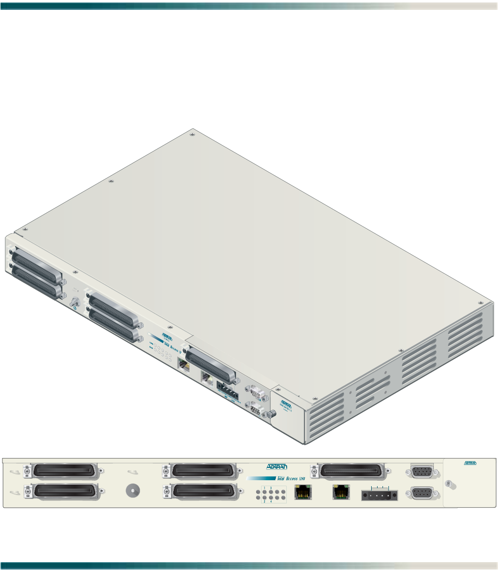
GENERAL
The Total Access 1248 (see Figure 1-1) is a Digital Subscriber Line Access Multiplexer
(DSLAM) system that is used to further extend Asymmetrical Digital Subscriber Line (ADSL)
services in the network.
Figure 1-1. Total Access 1248
1
2
3
4
T1/E1
5
6
7
8
FAN MODULE
1179675L1
ALARM
CRAFT
PWR
ALM
1179641L4
TOP:POTS BOTTOM: ADSL+POTS PORTS 1-24 TOP:POTS BOTTOM: ADSL+POTS PORTS 25-48
ETHERNET OUT
EXPANSION
T1/E1 1-8
-48V
.....
,5.0A
USE COPPER CONDUCTORS ONLY!
T1/E1
A B
-48V RET -48V RET
5
6
7
8
A

Total Access 1248 Octal T1 IMA DSLAM Installation and Maintenance Practice
1-2 61179641L4-5B
DESCRIPTION
The Total Access 1248 is a mini-DSLAM that accepts up to eight T1 network feeds assigned to
a single IMA group. Inverse Multiplexing over ATM (IMA) is a technology used to bond multiple
(DS1) links into a single data pipe.
The Total Access 1248 provides ADSL2+ service for up to 48 subscribers per unit. Plain Old
Telephone Service (POTS) is brought in from an on-board splitter and is placed on the same
pair as the ADSL2+ signal. Since ADSL2+ and POTS are transported on the same twisted pair,
the subscriber must use a low-pass filter on the line before attempting to use analog services.
The lines are configured for service with flow-through provisioning using a network configu-
ration application such as Telcordia’s Network Configuration (NCON). Permanent Virtual
Circuits (PVCs) in the ATM network to the subscriber’s chosen Internet Service Provider (ISP)
allow the subscriber access to the internet.
The Total Access 1248 is rack-mountable and measures 1.75 inches (1U) high, 17.25 inches
wide, and 11.125 inches deep (measurements do not include the mounting brackets). The
device may be powered using one or two –48 VDC sources, one for a non-redundant power
configuration, two for a redundant power configuration.
For detailed specification information on the Total Access 1248 system, refer to “Section 7,
Specifications”.
Features
The Total Access 1248 system incorporates the following features:
• Front panel indication of network, subscriber, and power/self-test status
• 48 ports of ADSL2+ plus POTS
• Redundant power inputs
• POTS service is not power dependent
• Removable front-accessible fan module (P/N 1179675L1)
• Supports IMA for up to eight T1/E1 IMA links
• ADSL options provisionable to accommodate both short and long haul T1s
• Provisioning and alarm monitoring via TL1, SNMP, local craft interface, and inband
management channel
• IMA group support (one group)
• Operates over an extended temperature range of –40°C to +70°C
• Interoperable with any ATM T1 IMA device built to current IMA specifications, which
includes the Total Access 3000 IMA Aggregation System
• Compliant with GR-63-CORE/GR-1089-CORE (NEBS), and Listed to the applicable UL
Safety Standard(s)
• Expansion capabilities for a total of three Total Access 1248 Expansion units to a Host unit
• In-band management of the expansion chassis
Description
61179641L4-5B 1-3
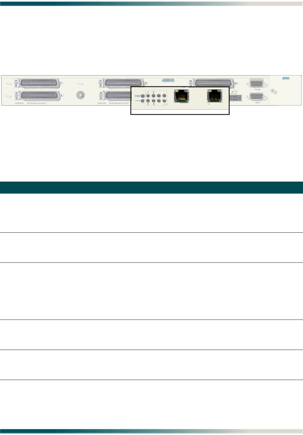
Front Panel LEDs
Figure 1-2 shows the location of the Total Access 1248 front panel LEDs. Upon initial
powering, the Total Access 1248 system performs a power up self-test. Once the power up
self-test is complete, the status LEDs reflect the condition of the hardware.
Figure 1-2. Total Access 1248 Front Panel LEDs
See Table 1-1 for a listing of LEDs and their status.
Table 1-1. Front Panel LEDs
Label Status Description
PWR Green
Yellow
Red
Off
Total Access 1248 is In Service
Total Access 1248 is Out of Service-Maintenance
Total Access 1248 Failed self-test
No power present on Total Access 1248
ALM Yellow
Red
Off
Total Access 1248 is reporting a Minor alarm
Total Access 1248 is reporting a Major alarm
No alarms reported on Total Access 1248
T1/E1 1–8 Green
4 Green Flashing
Yellow
4 Yellow Flashing
Red
Off
All good
T1/E1 OK, no IMA Sync
Signal present OOF
T1/E1 is in loopback
No signal
Facility unassigned
ETHERNET Green
4 Green Flashing
Yellow
Ethernet signal present
Ethernet with traffic
No signal
EXPANSION OUT Green
4 Green Flashing
Yellow
Connected to a downstream box
Connected with traffic
No signal
FAN M
O
D
U
L
E
1179675
L1
1179641L
4
P
O
RT
S
1-2
4
V
....
.
,5.0A
..
O
ND
UC
T
O
R
S
O
NLY
!
PWR
ALM
ETHERNET OUT
EXPANSION
T1/E1
5
6
7
8

Total Access 1248 Octal T1 IMA DSLAM Installation and Maintenance Practice
1-4 61179641L4-5B
Compliance
CAUTION
Electrostatic Discharge (ESD) can damage electronic modules.
When handling modules, wear an antistatic discharge wrist strap
to prevent damage to electronic components. Place modules in
antistatic packing material when transporting or storing. When
working on modules, always place them on an approved antistatic
mat that is electrically grounded.
The Total Access 1248 is NRTL listed to the applicable UL standards. The Total Access 1248
meets or exceeds all the applicable requirements of NEBS, Telcordia GR-63-CORE, and
GR-1089-CORE.
The Total Access 1248 is intended for deployment in Central Office type facilities, EEEs,
EECs, and locations where the NEC applies. Install the Total Access 1248 in a restricted
access location. Table 1-2 shows the compliance codes for the Total Access 1248.
This device complies with Part 15 of the FCC rules. Operation is subject to the following two
conditions:
1. This device may not cause harmful interference.
2. This device must accept any interference received, including interference that may cause
undesired operation.
Changes or modifications not expressly approved by ADTRAN could void the user’s authority
to operate this equipment.
Table 1-2. Compliance Codes
Configuration Codes Input Output
Power Code (PC) F C
Telecommunication Code (TC) X X
Installation Code (IC) A –
C A U T I O N !
SUBJECT TO ELECTROSTATIC DAMAGE
OR DECREASE IN RELIABILITY.
HANDLING PRECAUTIONS REQUIRED.

Description
61179641L4-5B 1-5
CAUTION
Per GR-1089-CORE the Total Access 1248 is designed and
intended for installation as part of a Common Bonding Network
(CBN). The Total Access 1248 is not designed nor intended for
installation as part of an Isolated Bonding Network (IBN).
CAUTION
Per GR-1089-CORE Section 9, the Total Access 1248 is intended to
be deployed in either a DC-C (common) or DC-I (isolated) installa-
tion of the Total Access 1248.
CAUTION
The Total Access 1248 Chassis frame ground terminal must be
connected to a reliable earth ground.
CAUTION
Connect to a reliably grounded –48 VDC source which is electri-
cally isolated from the AC source. The branch circuit overcurrent
protection shall be a fuse or circuit breaker rated minimum
48 VDC, maximum 3 amp.
NOTE
The POTS and ADSL+POTS ports are classified as Type 1, 3, and 5
as defined in Appendix B of GR-1089-CORE, Issue 4 and meets the
lightning and power fault criteria with any primary protector that
meets any of the voltage limits of GR-974-CORE or GR-1361-CORE
(i.e., carbon blocks, gas tubes, solid states, etc.). Solid-state
primary protectors are not recommended as they could affect the
signal integrity of the ADSL.
NOTE
Current limiting protectors are not required.

Total Access 1248 Octal T1 IMA DSLAM Installation and Maintenance Practice
1-6 61179641L4-5B
This page is intentionally blank.
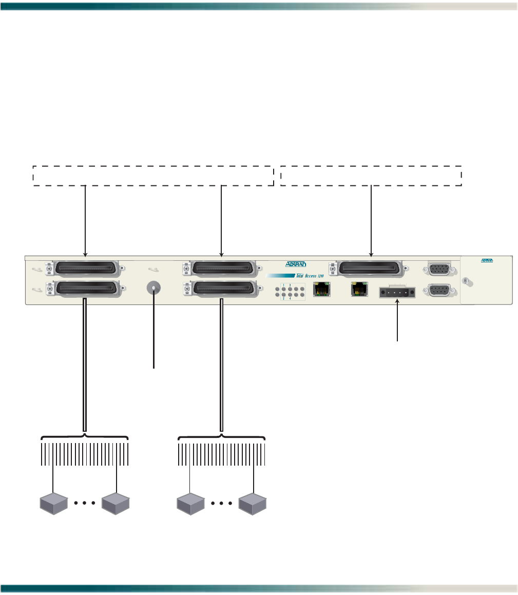
61179641L4-5B 2-1
Section 2
Application Guidelines
INTRODUCTION
The Total Access 1248 provides 48 ADSL2+ plus POTS ports downstream to the subscriber,
one to eight T1 IMA ports upstream to the network, local and remote management capabil-
ities, and front panel LEDs that indicate status. Figure 2-1 illustrates an operational scenario
for the Total Access 1248.
Figure 2-1. Total Access 1248 Operational Scenario
FAN MODULE
1179675L1
ALARM
CRAFT
PWR
ALM
1179641L4
TOP:POTS BOTTOM: ADSL+POTS PORTS 1-24 TOP:POTS BOTTOM: ADSL+POTS PORTS 25-48
ETHERNET OUT
EXPANSION
T1/E1 1-8
-48V
.....
,5.0A
USE COPPER CONDUCTORS ONLY!
T1/E1
A B
-48V RET -48V RET
5
6
7
8
A
POTS Ports 1-24 POTS Ports 25-48
Voice Switch or DLC Providing 1-48 POTS
Octal IMA Providing 1-8 DS1s
Central Office or Remote Terminal
Power
To Ground
24 Ports
ADSL2+ Plus POTS
SubscriberSubscriber
24 Ports
ADSL2+ Plus POTS
SubscriberSubscriber
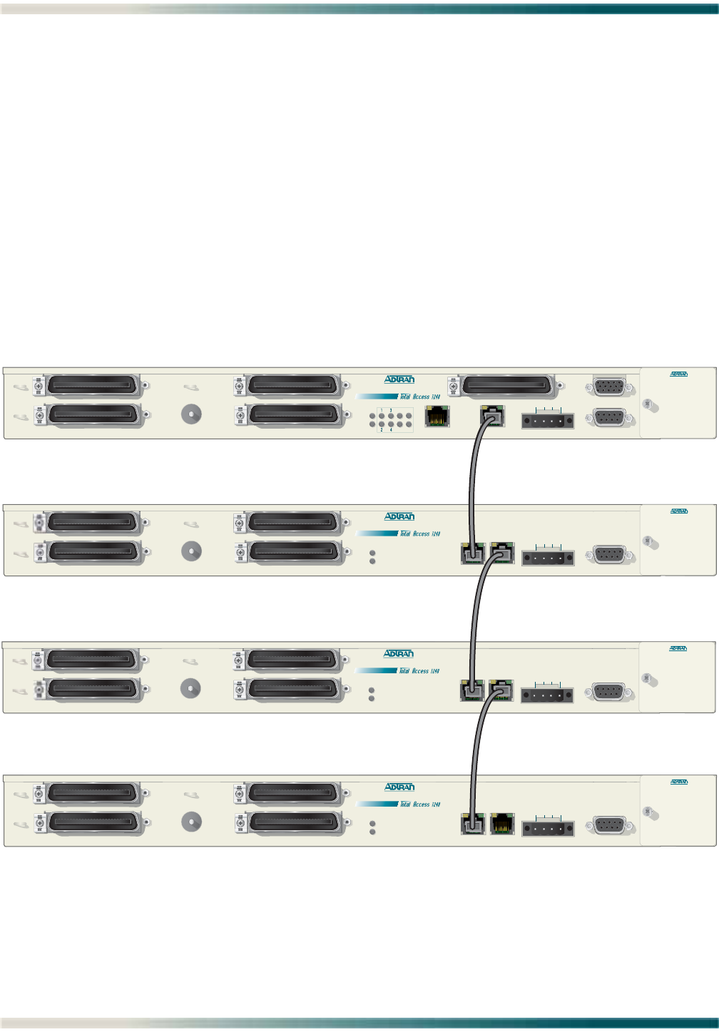
Total Access 1248 Octal T1 IMA DSLAM Installation and Maintenance Practice
2-2 61179641L4-5B
EXPANSION
Up to four Total Access 1248 systems can be connected together (see Figure 2-2). One of the
units must be a Total Access 1248 host unit (P/N 1179641L4) and the others are Total Access
1248 client units (P/N 1179641L5).
The client units (also referred to as Expansion units) have RJ-45 jacks, labeled EXPANSION IN
and EXPANSION OUT, for the purpose of expanding one to another.
The Total Access 1248 host unit provides the network connection for all of the client units. All
provisioning for the clients is completed through the host unit.
Beginning with the host, a Category 5e, non-crossover cable is connected from the EXPANSION
OUT jack of the host unit to the EXPANSION IN jack of the first client unit. Further connections
between client unit EXPANSION OUT jacks to EXPANSION IN jacks continue until a total of up to
three client units have been connected with the third client unit having only a connection to
the EXPANSION IN jack.
Figure 2-2. Expansion Cabling
Client 1
Client 2
Client 3
OUT
Host
FAN MODULE
1179675L1
ALARM
CRAFT
PWR
ALM
1179641L4
TOP:POTS BOTTOM: ADSL+POTS PORTS 1-24 TOP:POTS BOTTOM: ADSL+POTS PORTS 25-48
ETHERNET EXPANSION
T1/E1 1-8
-48V
.....
,5.0A
USE COPPER CONDUCTORS ONLY!
T1/E1
A B
-48V RET -48V RET
5
6
7
8
A
FAN MODUL E
1179675L1
CRAFT
PWR
ALM
1179641L5
TOP:POTS BOTTOM: ADSL+POTS PORTS 1-24 TOP:POTS BOTTOM: ADSL+POTS PORTS 25-48
OUT
EXPANSION
-48V
.....
,5.0A
USE COPPER CONDUCTORS ONLY!
A B
-48V RET -48V RET
EXPANSION
IN
FAN MODUL E
1179675L1
CRAFT
PWR
ALM
1179641L5
TOP:POTS BOTTOM: ADSL+POTS PORTS 1-24 TOP:POTS BOTTOM: ADSL+POTS PORTS 25-48
OUT
EXPANSION
-48V
.....
,5.0A
USE COPPER CONDUCTORS ONLY!
A B
-48V RET -48V RET
EXPANSION
IN
FAN MODULE
1179675L1
CRAFT
PWR
ALM
1179641L5
TOP:POTS BOTTOM: ADSL+POTS PORTS 1-24 TOP:POTS BOTTOM: ADSL+POTS PORTS 25-48
OUT
EXPANSION
-48V
.....
,5.0A
USE COPPER CONDUCTORS ONLY!
A B
-48V RET -48V RET
EXPANSION
IN

61179641L4-5B 3-1
Section 3
Installation
INTRODUCTION
CAUTION
Electrostatic Discharge (ESD) can damage electronic units. When
handling units, wear an antistatic discharge wrist strap to prevent
damage to electronic components. Place units in antistatic packing
material when transporting or storing. When working on units,
always place them on an approved antistatic mat that is electrically
grounded.
After unpacking the Total Access 1248, inspect it for damage. If damage has occurred, file a
claim with the carrier and then contact ADTRAN Customer Service. Refer to “Appendix A,
Warranty” for further information. If possible, keep the original shipping container to return
the Total Access 1248 for repair or for verification of shipping damage.
C A U T I O N !
SUBJECT TO ELECTROSTATIC DAMAGE
OR DECREASE IN RELIABILITY.
HANDLING PRECAUTIONS REQUIRED.

Total Access 1248 Octal T1 IMA DSLAM Installation and Maintenance Practice
3-2 61179641L4-5B
Shipping Contents
The shipping container for the Total Access 1248 includes the contents shown in Table 3-1.
Required Tools
The following tools and materials are required to install the Total Access 1248:
•Wire-wrap tool
• #2 phillips-head screwdriver
• #1 phillips-head screwdriver
• Straight-slot screwdriver
• Multimeter (ohmmeter and voltmeter)
• Crimping tool for power lugs
• Wire strippers
• Side cutters
Table 3-1. Total Access 1248 Shipping Contents
Description Part Number Quantity
Total Access 1248 Octal T1 IMA DSLAM 1179641L4 1
Total Access 1248 Octal T1 IMA DSLAM Installation and
Maintenance Practice
61179641L4-5 1
Cable Assembly, Ground Wire 3125P037@ 1
Terminal Block 32024CON10 1
Mounting Bracket, 19-inch 3265540 2
Mounting Bracket, 23-inch 3265541 2
Screw, 8-32 × 1/4 3276003007 4
Screw, 8-32 × 3/16 327611034 4
Cable Tie 3292032 5

Installation Prerequisites
61179641L4-5B 3-3
INSTALLATION PREREQUISITES
The following items should be completed prior to installing the Total Access 1248:
1. Make sure that the network feed is in place.
2. Make sure that local power is available and that the required fuses are installed.
CAUTION
The maximum power draw for the Total Access 1248 system is 75
watts.
ADTRAN recommends an external fuse rated at 3.0 amps.
3. Complete Table 3-2 with the information that is needed to turn-up and provision the Total
Access 1248.
Table 3-2. Turn-up and Provisioning Prerequisite information
Item Description Value
Network Feed/Aggregation System IP Address
Network Feed/Aggregation System Port
Total Access 1248 IP Address
Total Access 1248 Default Gateway
Total Access 1248 Subnet Mask
Total Access 1248 VPI/VCI
Number of Network Facilities Feeding the Total Access 1248
CLEI Code/System Name

Total Access 1248 Octal T1 IMA DSLAM Installation and Maintenance Practice
3-4 61179641L4-5B
INSTALLATION STEPS
The following steps are required to install the Total Access 1248. Each step has an associated
procedure which is referenced below the step. Each procedure provides detailed information
for completing the step.
1. Mount the Total Access 1248 system with the appropriate hardware.
For detailed information, refer to “Mounting the Total Access 1248” on page 3-5.
2. Ground the Total Access 1248.
For detailed information, refer to “Ground Connection” on page 3-8.
3. Make the power connections to the Total Access 1248.
For detailed information, refer to “Power Connection” on page 3-9.
4. Connect the Ethernet cable to the Total Access 1248.
For detailed information, refer to “Ethernet Connection” on page 3-11.
5. Connect the DB-15 male alarm cable connector to the Total Access 1248 and wire-wrap
the connections to an alarm panel.
For detailed information, refer to “Alarm Connections” on page 3-12.
6. Connect the network cable.
For detailed information, refer to “Network Connections” on page 3-13.
7. Connect the ADSL2+ plus POTS and POTS cables.
For detailed information, refer to “ADSL2+ Plus POTS Connections” on page 3-14.
8. Turn-up the Total Access 1248.
For detailed information, refer to “Quick Turn-up Steps” on page 3-19.
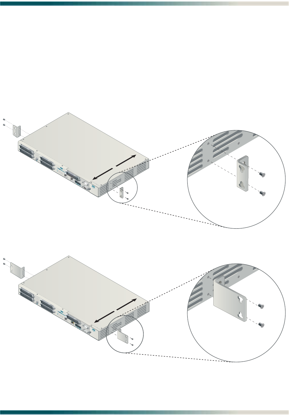
Installation Steps
61179641L4-5B 3-5
Mounting the Total Access 1248
The Total Access 1248 is shipped with two sets of mounting brackets that accommodate either
a 19-inch or 23-inch rack.
• The mounting brackets used for a 19-inch rack are part number 3265540.
• The mounting brackets used for a 23-inch rack are part number 3265541.
The mounting brackets provide for flush or mid-mounting configurations. Figure 3-1 shows
the Total Access 1248 mounting bracket installation options. Four screws (supplied with the
unit) are required for mounting the brackets to the system.
Figure 3-1. Mounting Brackets
1
2
3
4
T1/E1
5
6
7
8
FRONT BACK
P/N 3265540
19-inch Mounting Brackets
1
2
3
4
T1/E1
5
6
7
8
FRONT BACK
P/N 3265541
23-inch Mounting Brackets
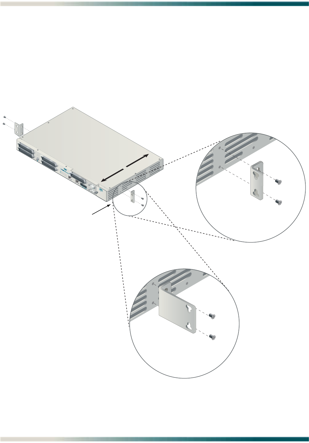
Total Access 1248 Octal T1 IMA DSLAM Installation and Maintenance Practice
3-6 61179641L4-5B
Flush-mount
For flush-mount systems, the Total Access 1248 must be mounted from the front of the rack,
with mounting brackets in the flush-mounting orientation (see Figure 3-2). When flush-
mounting a Total Access 1248 in the rack, use a #2 phillips-head screwdriver and attach the
mounting brackets to the front screw holes with the flanges containing the slotted rack-
mounting holes facing the front of the Total Access 1248.
Using four screws appropriate for the mounting rack and the appropriate screwdriver, secure
the Total Access 1248 in place on the rack.
Figure 3-2. Flush-mount Orientation
1
2
3
4
T1/E1
5
6
7
8
FRONT BACK
19-inch Mounting Brackets
23-inch Mounting Brackets
Flush-mount Orientation

Installation Steps
61179641L4-5B 3-7
Mid-mount
For mid-mount systems, the Total Access 1248 must be mounted from the front of the rack,
with mounting brackets in the mid-mounting orientation (see Figure 3-3). For mid-mounting a
Total Access 1248 in the rack, use a #2 phillips-head screwdriver and attach the mounting
brackets to the rear screw holes with the flanges containing the slotted rack-mounting holes
facing the front of the Total Access 1248.
Using four screws appropriate for the mounting rack and the appropriate screwdriver, secure
the Total Access 1248 in place on the rack.
Figure 3-3. Mid-mount Orientation
1
2
3
4
T1/E1
5
6
7
8
FRONT BACK
Mid-mount Orientation
19-inch Mounting Brackets
23-inch Mounting Brackets
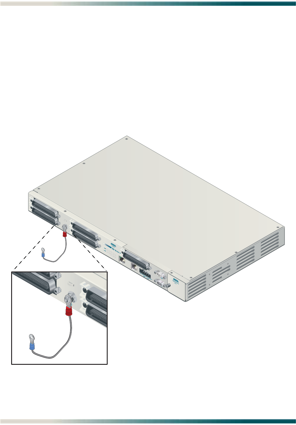
Total Access 1248 Octal T1 IMA DSLAM Installation and Maintenance Practice
3-8 61179641L4-5B
Ground Connection
The ground wire must be 12 to 18 AWG, however, it must be as large or larger than the wire
used for power. The Total Access 1248 must be grounded to a reliable grounding source.
To connect the ground wire, perform the following steps:
1. Connect the ground wire (fitted with a loop terminal end) to the ground lug on the front of
the Total Access 1248 (see Figure 3-4).
2. Clean the surface of the frame ground source and apply an appropriate antioxidant.
3. Connect the other end of the ground wire to the grounded frame.
4. Using an ohmmeter, verify continuity between the ground lug and a known good frame
ground. The reading should be less than 1 ohm.
Figure 3-4. Total Access 1248 Ground Connection
1
2
3
4
T1/E1
5
6
7
8

Installation Steps
61179641L4-5B 3-9
Power Connection
The Total Access 1248 provides redundant power inputs. Two sources of –48 VDC must be
provided to use the redundant power feature. The power wires must be 12 to 18 AWG
stranded copper. The Total Access 1248 uses a four-point terminal block (see Figure 3-5) to
accept the –48 VDC and –48 VDC RET leads.
Figure 3-5. Four-point Terminal Block
NOTE
If a non-redundant power configuration is to be implemented, use
the connections marked –48 VDC A and –48 VDC A RET.
To connect the power source, perform the following steps:
1. With the power disconnected at the source, remove approximately 1/4-inch of insulation
from the ends of both power wires.
NOTE
ADTRAN recommends an external fuse rated at 3.0 amps.
2. Using a small flat-head screwdriver, loosen the setscrews on the top of the terminal block.
3. Insert the bare wire into the opening on the front of the terminal block, making sure that
the wire is inserted correctly according to the labeling on the unit above the terminal
block.
4. While holding the wire in place, tighten the setscrew until the wire is secure.
5. Repeat steps 1 to 4 until all power leads are connected.
6. Apply power to the Total Access 1248 and test the voltage and polarity on the terminal
block using the tops of the setscrews as test points.
-48 VDC B RET
-48 VDC A RET
-48 VDC A
-48 VDC B
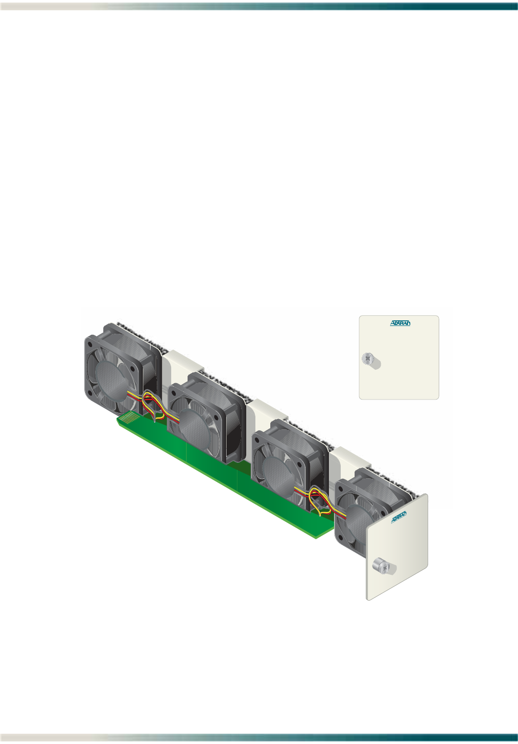
Total Access 1248 Octal T1 IMA DSLAM Installation and Maintenance Practice
3-10 61179641L4-5B
Fans/Fan Filter
The Total Access 1248 is shipped with a pre-installed fan module (P/N 1179675L1). The fan
module is located on the right side of the unit, and contains four fans (see Figure 3-6). The
fans move filtered air (if the filter is installed) into the Total Access 1248 chassis and out
through the exhaust slots on the left side.
The fans are monitored by the system and are tested during power-up or when a fan module is
installed. The fans can also be manually tested from the Self-test Menu. If any fan fails, the
PWR LED lights red indicating a self-test failure. At the same time, a minor alarm is generated
indicating the problem. This also occurs if the fan(s) fail during use. If the fan module is
removed from the shelf for replacement and/or maintenance, the alarm can be suppressed
depending on the fan alarm delay.
The fans are thermostatically controlled and are only powered on when necessary. Initially,
only one fan is activated. The fans are alternated to maintain the specified temperature level.
If the temperature continues to rise, all fans are used at the same time. In the event the
temperature still remains too high, the ADSL circuits are shut down until a safe operating
temperature is reached.
The fan module and fan filter are field-replaceable.
Figure 3-6. Total Access 1248 Fan Module
FAN MODULE
1179675L1
FAN MODULE
1179675L1
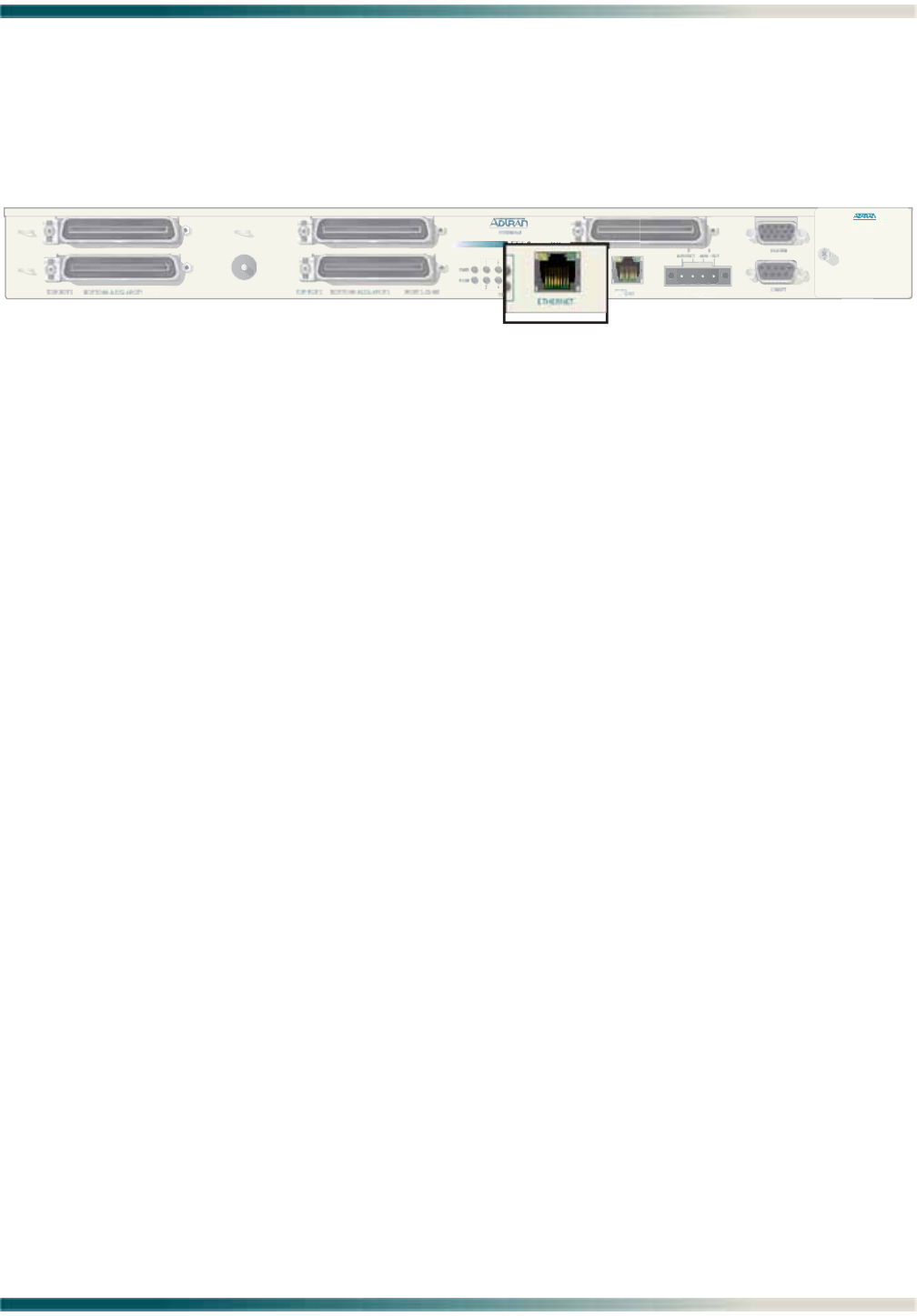
Installation Steps
61179641L4-5B 3-11
Ethernet Connection
The Total Access 1248 interfaces with networks for management through an Ethernet port
(see Figure 3-7).
Figure 3-7. Total Access 1248 Ethernet Port
The following Ethernet protocols are supported:
• IEEE 802.3, 10/100Base-T
• DHCP Client Mode for Management
•SNMP
FAN M
O
D
U
L
E
1179675
L1
P
O
RT
S
1-2
4
EXPANSION
-
48V
....
.
,5.0A
.
US
E
CO
PPER
CO
ND
UC
T
O
R
S
O
NLY
!
ETHERNET

Total Access 1248 Octal T1 IMA DSLAM Installation and Maintenance Practice
3-12 61179641L4-5B
Alarm Connections
The Total Access 1248 provides an alarm port (see Figure 3-8) with three auxiliary alarm
inputs and three alarm outputs (Major, Minor, and Critical). Alarm inputs are activated by
shorting A and B contacts (closing an externally connected relay). The outputs provide both
normally open and normally closed pins (through internal relay contacts) for proper operation
with a variety of alarm panels. Each alarm event generates an autonomous TL1 message that
is transmitted via the in-band management channel to a monitoring device.
A cable with a high density DB-15 male connector on one end and a stub at the other end is
available (P/N 1196DB901L1) for wire-wrap connections to an alarm panel.
Figure 3-8. Total Access 1248 Alarm Connection
The alarm pinouts are shown in Table 3-3.
Table 3-3. Alarm Pinouts
Pin Color Contact Description
1Red Alarm 3 Input - A
2Red/Black Alarm 1 Input - B
3Red/White Critical Alarm COM
4Orange Minor Alarm COM
5Orange/Black Major Alarm COM
6White Alarm 3 Input - B
7White/Black Alarm 2 Input - A
8Black Critical Alarm NC
9Black/White Minor Alarm NC
10 Blue/Black Major Alarm NC
11 Blue/White Alarm 2 Input - B
12 Blue Alarm 1 Input - A
13 Green/Black Critical Alarm NO
14 Green/White Minor Alarm NO
15 Green Major Alarm NO
PORTS 1-2
4
ALARM

Installation Steps
61179641L4-5B 3-13
Network Connections
Network connections are accomplished via the 50-pin amphenol connector labeled T1/E1 1-8
(see Figure 3-9). See Table 3-4 for the pinout of the T1/E1 interface.
Figure 3-9. Total Access 1248 Network Connection
Table 3-4. T1/E1 Interface Pinout
Pin Numbers Description
1, 26 RX Tip/Ring 1
2, 27 TX Tip/Ring 1
3, 28 RX Tip/Ring 2
4, 29 TX Tip/Ring 2
5, 30 RX Tip/Ring 3
6, 31 TX Tip/Ring 3
7, 32 RX Tip/Ring 4
8, 33 TX Tip/Ring 4
9, 34 RX Tip/Ring 5
10, 35 TX Tip/Ring 5
11, 36 RX Tip/Ring 6
12, 37 TX Tip/Ring 6
13, 38 RX Tip/Ring 7
14, 39 TX Tip/Ring 7
15, 40 RX Tip/Ring 8
16, 41 TX Tip/Ring 8
17–24 Unused
42–49 Unused
25, 50 Unused
FAN MODU L
E
117
96
7
5
L
1
11
7
9641
L
4
PORTS 1-2
4
EXPANSION
-
4
8V
.....
,5.0A
.
US
E
CO
PPER
CO
NDU
C
T
O
R
S
O
NLY!
T1/E1 1-8
A
-48V RET -48V RET
A

Total Access 1248 Octal T1 IMA DSLAM Installation and Maintenance Practice
3-14 61179641L4-5B
ADSL2+ Plus POTS Connections
The Total Access 1248 utilizes four 25-pair amphenol connectors (see Figure 3-10), which are
used as follows:
• Two amphenols for connection to the POTS pairs
• Two amphenols for connection to the ADSL2+ plus POTS pairs
Figure 3-10. Total Access 1248 POTS and ADSL+POTS Connections
POTS Interface
Each POTS interface on the Total Access 1248 accepts a POTS signal from the Central Office
(CO) and passes it through to the ADSL2+ plus POTS interface for delivery to the subscriber.
POTS service is not affected by loss of power to the unit.
ADSL2+ Plus POTS Interface
Each ADSL2+ plus POTS interface provides transport for standard POTS from the CO to the
subscriber. The frequency ranges for Total Access 1248 deployment are as follows:
• POTS accommodates frequency ranges up to 4 kHz
• ADSL and ADSL2 accommodates frequency ranges up to 1.1 MHz
• ADSL2+ accommodates frequency ranges up to 2.2 MHz
Any analog devices connected to this interface must use a low-pass filter to prevent high
frequencies from interfering with the device.
FAN M
O
D
UL
E
117
96
7
5
L1
ETHERNET
O
U
T
O
EXPANSION
EXPAN
-48
V
....
.
,5.0A
.
US
E
CO
PPER
CO
NDU
C
T
O
R
S
O
NLY!
-
4
8
V
R
E
T
-48V
R
E
T
TOP:POTS BOTTOM: ADSL+POTS PORTS 1-24 TOP:POTS BOTTOM: ADSL+POTS PORTS 25-48

Installation Steps
61179641L4-5B 3-15
POTS Connection
The Total Access 1248 must be connected to a POTS source to provide POTS to the
subscribers. In a standard configuration, the POTS will be brought in from a nearby cross-
connect. The Total Access 1248 accepts the POTS signal on the top two amphenol connectors
labeled POTS. There is a one-to-one correlation between the pins on the POTS amphenol
connectors and the pins on the ADSL plus POTS (ADSL+POTS) amphenol connectors. Refer to
the “Customer Connections (ADSL+POTS)” section below for more information.
To establish a POTS connection, perform the following steps:
1. Connect the cables with the 25-pair female amphenol connectors to the male amphenol
connectors provided, labeled POTS.
2. Tighten the screws (normally provided with each amphenol connector attached to the
cable) on the right side of each amphenol connector, and use the cable ties (provided)
threaded through the tie-down brackets (provided) to secure the left side of the amphenol
connectors.
NOTE
This cable tie may be used to assist in routing the power cables
and the ADSL+POTS cables that originate from the right most
amphenol connector.
NOTE
The POTS interface may be connected to the outside plant.
Customer Connections (ADSL+POTS)
The Total Access 1248 provides 48 ADSL+POTS ports on two 50-pin male amphenol
connectors. POTS is brought in from the CO on the POTS amphenol connectors as described
in the preceding section. The ADSL is generated locally and placed on the same pair as the
corresponding POTS signal for delivery to the subscriber.
There is a one-to-one correlation between the pins on the ADSL+POTS amphenol connectors
and the pins on the POTS amphenol connectors. Refer to the “POTS Connection” section above
for more information. The 25th pair is not used. To establish the ADSL+POTS connection,
perform the following steps:
1. Connect the 25-pair female amphenol connectors to the male amphenol connectors pro-
vided, labeled ADSL+POTS.
2. Tighten the screws (normally provided with each amphenol connector attached to the
cable) on the right side of each amphenol connector, and use the cable ties (provided)
threaded through the tie-down brackets (provided) to secure the left side of the amphenol
connectors.
The pin assignments for the left and right POTS and ADSL+POTS cables are shown in
Table 3-5 and Table 3-6.

Total Access 1248 Octal T1 IMA DSLAM Installation and Maintenance Practice
3-16 61179641L4-5B
Table 3-5. POTS and ADSL+POTS Cable Pin Assignments for Left-most Connectors
Pair # Pins R.T. Pair # Pins R.T.
11, 26 13 13, 38
22, 27 14 14, 39
33, 28 15 15, 40
44, 29 16 16, 41
55, 30 17 17, 42
66, 31 18 18, 43
77, 32 19 19, 44
88, 33 20 20, 45
99, 34 21 21, 46
10 10, 35 22 22, 47
11 11, 36 23 23, 48
12 12, 37 24 24, 49
25 25, 50 Not used
Table 3-6. POTS and ADSL+POTS Cable Pin Assignments for Right-most Connectors
Pair # Pins R.T. Pair # Pins R.T.
26 1, 26 38 13, 38
27 2, 27 39 14, 39
28 3, 28 40 15, 40
29 4, 29 41 16, 41
30 5, 30 42 17, 42
31 6, 31 43 18, 43
32 7, 32 44 19, 44
33 8, 33 45 20, 45
34 9, 34 46 21, 46
35 10, 35 47 22, 47
36 11, 36 48 23, 48
37 12, 37 49 24, 49
50 25, 50 Not used
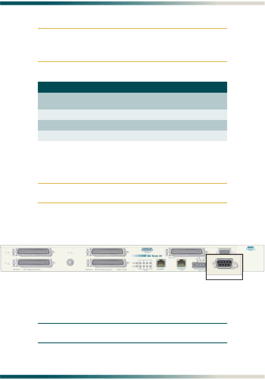
Total Access 1200F Conversion
61179641L4-5B 3-17
TOTAL ACCESS 1200F CONVERSION
CAUTION
The order of subtended Total Access 1200 Series DSLAMS must be
preserved when connecting to the Total Access 1200F for transla-
tion to the legacy ATM mode PVCs. See Table 3-7.
Existing Total Access 1200 Series DSLAM installations require a software upgrade to convert
the Total Access 1200 Series DSLAMs to function with a Total Access 1200F.
To upgrade each Total Access 1200 Series DSLAM, perform the following steps:
CAUTION
Upgrading the firmware disrupts DSL service to the customer.
1. Connect a VT100-capable laptop/terminal to the CRAFT port of a Total Access 1200 Series
DSLAM (see Figure 3-11 for the location of the CRAFT port).
Figure 3-11. Total Access 1100 Series DSLAM Craft Port
2. Set the terminal baud rate to 9600 baud, 8 data bits, no parity, 1 stop bit, and no flow
control.
NOTE
The 4-MB Flash Upgrade must be made at 9600 baud.
Table 3-7. Order of Subtended Clients
Total Access 1200F Expansion Port Total Access 1200 Series Client
1Total Access 1100 Series Host
(Client 1)
2Client 2
3Client 3
4Client 4
P
O
RT
S
1-2
4
CRAFT

Total Access 1248 Octal T1 IMA DSLAM Installation and Maintenance Practice
3-18 61179641L4-5B
3. Press and hold the Y key on the terminal keyboard and apply power to the Total Access
1200 Series DSLAM.
4. When prompted, select 38400 for a faster transfer rate (20 minutes at 38400 compared to
60 minutes at 9600).
If using HyperTerminal, go off-line, select properties, change the baud rate, then go back
online. VT100 settings should be set as follows:
• Baud Rate: 38400
• Data Bits: 8
•Parity: None
• Stop Bits: 1
• Flow Control: None
If properly connected, a row of CCCCs should begin to display on the screen.
5. Download the current file identified by network administration using the Y-Modem
protocol.
If using HyperTerminal, use the Transfer > Send File... Browse... dialogue and identify the
file by name and location. Select YModem, then click Send.
6. Several messages are displayed that report system progress for the upgrade procedure,
including the following:
• Erasing Flash
• Erase Complete
• Programming Flash
• Programming Complete
• Comparing Flash to SDRAM
• Verify Done
• Please set Baud Rate to 9600 and Reboot Unit Now
7. Reboot the Total Access 1200 Series DSLAM when the download is completed.
8. Repeat steps 1 through 7 for each Total Access 1200 Series DSLAM.
9. Connect the Total Access 1200F expansion cables at the DSLAM end.
10. Provision, test, and turn up the equipment. Refer to “Section 4, Provisioning Defaults”
and “Section 5, User Interface” of the Total Access 1200F Installation and Maintenance
Practice (P/N 61179660L1-5) for detailed instructions on provisioning the equipment.
NOTE
Access to the Total Access 1200 Series units is now available
through the Total Access 1200F craft access of Inband
Management access ports.

Quick Turn-up Steps
61179641L4-5B 3-19
QUICK TURN-UP STEPS
Perform the following steps to complete a basic T1 turn-up of the Total Access 1248 system:
1. Connect VT100 terminal or personal computer emulating a VT100 terminal to the Total
Access 1248 craft port.
For more information, refer to “Craft Interface” on page 5-1.
2. Press CTRL+R until the Login screen (see Figure 3-12) displays.
Figure 3-12. Login Screen
3. Enter the default username, “ADMIN” (or the configured username with System
Administrator privileges), and press ENTER.
4. Enter the default password, “PASSWORD” (or the configured password), and press ENTER.
NOTE
The username and password fields are case sensitive. The default
values are all uppercase. For more information, refer to “Password
Control Menu” on page 5-49.
The Total Access 1248 Main menu displays (see Figure 3-13).
Total Access 1248
Login: ADMIN
Password: ********

Total Access 1248 Octal T1 IMA DSLAM Installation and Maintenance Practice
3-20 61179641L4-5B
Figure 3-13. Total Access 1248 Main Menu
5. Provision the appropriate network termination.
6. From the Total Access 1248 Main menu, select Network Port, and press ENTER.
The Network Port menu (see Figure 3-14) displays.
Figure 3-14. Network Port Menu
7. From the Network Port menu, select T1, and press ENTER.
TID: HSVL00001 Total Access 1248 MM/DD/YY HH:MM
Unacknowledged Alarms: None
Total Access 1248
1. Configuration
2. ATM Circuit Management
3. System Management
4. Network Port
5. DSL Menus
6. System Alarms
7. System Event Log
8. Contact Information
9. Enter TL1 mode
10. Logoff
Selection :
'?' - System Help Screen
TID: HSVL00001 Total Access 1248 MM/DD/YY HH:MM
Unacknowledged Alarms: None
Network Port
1. T1
2. IMA
3. Select T1/E1 Mode
Selection :
'?' - System Help Screen

Quick Turn-up Steps
61179641L4-5B 3-21
8. The T1 Main Menu (see Figure 3-15) displays.
Figure 3-15. T1 Main Menu
9. From the T1 Main Menu, select T1 Provisioning, and press ENTER.
The T1 Provisioning menu (see Figure 3-16) displays.
Figure 3-16. T1 Provisioning Screen
TID: HSVL00001 Total Access 1248 MM/DD/YY HH:MM
Unacknowledged Alarms: None
T1 Main Menu
1. T1 Provisioning
2. T1 Status
3. T1 Performance
4. Test
5. Restore T1 Factory Defaults
Selection :
'?' - System Help Screen
TID: HSVL00001 Total Access 1248 MM/DD/YY HH:MM
Unacknowledged Alarms: None
T1 Provisioning for # 1
1. Type DSX
2. Framing ESF
3. Line Code B8ZS
4. Line Build Out 0 - 133 ft
'N' - Next T1 Port 'P' - Previous T1 Port
Selection :
'?' - System Help Screen

Total Access 1248 Octal T1 IMA DSLAM Installation and Maintenance Practice
3-22 61179641L4-5B
10. From the T1 Provisioning menu, configure the Type, Framing, Line Code, and Line Build Out
setting to match the settings of the T1s provided. Press N to access the next T1 to
configure and continue this process until all the T1s are properly configured.
11. From the T1 Provisioning menu, press ESC to return to the T1 Main Menu.
12. From the T1 Main Menu, select T1 Status, and press ENTER.
13. From the T1 Status menu, confirm that the T1s do not have active alarms.
NOTE
If the T1s have active alarms, this is an indication of a network feed
issue.
14. From the T1 Status menu, press ESC until the Network Port menu displays.
15. From the Network Port menu, select IMA and press ENTER.
16. From the IMA Main Menu, select Provisioning, and press ENTER.
17. From the IMA Provisioning menu, select IMA Facility, and press ENTER.
18. From the IMA Facility Provisioning for # 1 menu, select Facility Operation Mode, and press
ENTER.
19. From the Operation Mode for Facility for # 1 menu, provision the facilities as appropriate.
For more information, refer to “Operation Mode for Facility Menu” on page 5-116.
The default settings assign the 8 facilities to the IMA Group.
20. From the Operation Mode for Facility for # 1 menu, press ESC until the IMA Provisioning
menu displays.
21. From the IMA Provisioning menu, select IMA Group, and press ENTER.
22. From the IMA Group Provisioning menu, select Group Operation Mode, and press ENTER.
23. From the Group Operation Mode menu, select In Service, and press ENTER.
24. Press ESC until the Main menu displays.
25. From the Main menu, select System Management, and press ENTER
26. From the System Management menu, select IP Address, and press ENTER.
27. From the Mode Selection and Current IP Settings menu, verify that the Mode is set to
Static.
28. From the Mode Selection and Current IP Settings menu, select Configure IP, and press
ENTER.
29. From the Status IP Settings - for IP over ATM menu, configure the following fields:
• IP Address
•Subnet Mask
•VPI/VCI
•Default Gateway

Quick Turn-up Steps
61179641L4-5B 3-23
30. Add the IP address to the network routers/servers.
31. Press ESC until the System Management menu displays.
32. From the System Management menu, select Test IP Address, and press ENTER.
The Test IP Address menu is displayed (see Figure 3-17).
Figure 3-17. Test IP Address Menu
33. From the Test IP Address menu, select IP Address, and press ENTER.
The IP Address field is highlighted.
34. Enter the IP address of the default gateway to Ping in decimal dot format, and press ENTER.
35. From the IP Address menu, select Start Ping, and press ENTER to initiate the Ping.
36. Confirm that the Traffic Descriptor default values match the local practices and modify
accordingly.
37. Add the Service Profiles to the Total Access 1248 for the approved service.
38. Pre-provision the system using the information provided in the appropriate work order.
39. Place the DSL ports In Service, as needed.
TID: HSVL00001 Total Access 1248
Unacknowledged Alarms: None
Test IP Address
1. IP Address Not configured
2. Ping Timeout 1 secs 4. Start Ping
3. Number of Pings 4 pings 5. Start Traceroute
Selection :
'?' - System Help Screen

Total Access 1248 Octal T1 IMA DSLAM Installation and Maintenance Practice
3-24 61179641L4-5B
This page is intentionally blank.

61179641L4-5B 4-1
Section 4
Provisioning Defaults
INTRODUCTION
The Total Access 1248 system default provisioning options are shown in Table 4-1. For
detailed information on the Total Access 1248 menus, refer to “Section 5, User Interface”.
Table 4-1. Default Provisioning Options
Provisioning Option Available Options Default Setting
ATM Circuit Options
PVCs User definable (Each ADSL connection
must have at least one PVC/PVP for
data flow.)
None
Traffic Descriptors
(Service options)
UBR; CBR; VBR-rt; VBR-nrt UBR
System Management
Password Control
Set Login Name User defined Not configured
Access Level Read Only; Technician; System
Administrator
Not configured
Control Level Read Only; Read/Write Not configured
Allow SNMP Security
Management
Enabled; Disabled Disabled
Set Menus Idle Logout
Time
1–60 minutes 10 minutes
TL1 Menus Idle Logout
Time
1–120 minutes 30 minutes
TL1 Inband Idle Logout
Time
1–120 minutes 120 minutes

Total Access 1248 Octal T1 IMA DSLAM Installation and Maintenance Practice
4-2 61179641L4-5B
IP Address
IP Feed RFC1483 Routed; IP over Ethernet;
RFC1483 Bridged
RFC1483 Routed
IP Mode Dynamic; Static Dynamic
IP Address 0–255.0–255.0–255.0–255 0.0.0.0
Subnet Mask 0–255.0–255.0–255.0–255 0.0.0.0
Default Gateway 0–255.0–255.0–255.0–255 Not configured
TFTP IP Address 0–255.0–255.0–255.0–255 Not configured
TL1 Port Number 1023 or greater 13001
TL1 IP Transport Type TCP; UDP TCP
Test IP Address
Test IP Address 0–255.0–255.0–255.0–255 Not configured
Ping Timeout 1–10 seconds 1 second
Number of Pings 1–8 pings 4 pings
Baud Rate
Baud Rate 9600; 19200; 38400 9600
SNMP Contact Information
Contact 55-character string ADTRAN, Inc. (256) 963-8000
Name 55-character string Not configured
Location 55-character string Customer specified
SNMP Community Names
Name 32-character string Not Configured *
IP Address 0–255.0–255.0–255.0–255 0.0.0.0
Privileges Read/Write; Read
SNMP Trap Hosts
Trap Port 1–65535 162
IP Address 0–255.0–255.0–255.0–255 Not configured
Version SNMPv1; SNMPv2 Not Configured
SNMP Traps Enabled
SNMP Traps Enabled Yes; No Yes
Table 4-1. Default Provisioning Options (Continued)
Provisioning Option Available Options Default Setting

Introduction
61179641L4-5B 4-3
External Alarms
Alarm Name 25-character string External Alarm Input #
Alarm Severity Critical; Major; Minor; Load shedding Minor
Fan Alarm Delay 0–15 minutes 10 Minutes
Network Port
E1 Provisioning
E1 Framing FAS; FAS+CRC FAS+CRC
E1 Line Code HDB3; AMI HDB3
T1 Provisioning
T1 Type DSX; T1 DSX
T1 Framing ESF; SF ESF
T1 Line Code B8ZS; AMI B8ZS
T1 Line Build Out DSX Type: 0-133 ft; 133-266 ft;
266-399 ft; 399-533 ft; 533-655 ft
T1 Type: 0 dB; –7.5 dB; –15 dB;–22.5
dB
0–133 ft
0 dB
IMA Provisioning
Facility Operation Mode IMA_Group; Unassigned; Pass-through IMA_Group
Group Operation Mode In Service; Out of Service-Maintenance;
Out of Service-Unassigned
Out of Service-Maintenance
IMA Transmit ID 0-255 101
IMA Transmit Frame
Length
32; 64; 128; 256 128
Minimum TX Active Links 1-4 1
Minimum RX Active Links 1-4 1
Maximum Link Diff Delay 0-100 100
Scrambler Enable; Disable Disabled
DSL Menus
ADSL Provisioning
Card Service State In Service; Out of Service-Maintenance;
Out of Service-Unassigned
In Service
Line Service State In Service; Out of Service-Maintenance;
Out of Service-Unassigned
Out of Service-Maintenance
Table 4-1. Default Provisioning Options (Continued)
Provisioning Option Available Options Default Setting

Total Access 1248 Octal T1 IMA DSLAM Installation and Maintenance Practice
4-4 61179641L4-5B
* SNMP Community Names are case-sensitive. The Total Access 1248 system provides two SNMP Community
Name accounts with the following defaults:
• Name: private
• IP Address: 0.0.0.0
• Privileges: Read/Write
• Name: public
• IP Address: 0.0.0.0
• Privileges: Read
Service Mode Multimode; T1.413; G.dmt; G.lite;
ADSL2; ADSL2.lite; ADSL2+; READSL;
Legacy Multimode
Multimode
Cabinet Mode Disabled; Enabled Disabled
Hamband Mask Disabled; Enabled Disabled
Link Down Alarm Disabled; Enabled Disabled
Rate Mode Fixed; Rate Adaptive Rate adaptive
Line Type Interleave; Fast Fast
Table 4-1. Default Provisioning Options (Continued)
Provisioning Option Available Options Default Setting
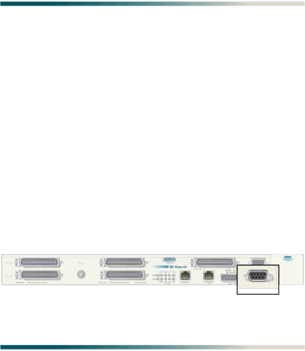
61179641L4-5B 5-1
Section 5
User Interface
INTRODUCTION
This section provides detailed information on the following:
•“System Management” on page 5-1
•“Logging on to the Total Access 1248” on page 5-3
•“Menu Structure” on page 5-4
•“Menu Navigation” on page 5-5
•“Menu Tree” on page 5-9
•“Menu Descriptions” on page 5-15
SYSTEM MANAGEMENT
Total Access 1248 system management and provisioning is facilitated by a series of intuitive
menus that are accessible on a computer screen. The Total Access 1248 provides two methods
for management access:
•“Craft Interface” on page 5-1
•“Inband Management Interface” on page 5-2
Craft Interface
Connection to the Total Access 1248 system menus can be made through the DB-9 connector,
labeled CRAFT, on the front of the Total Access 1248 system. A DB-9 straight cable is required.
The craft port is located behind the front panel cover (see Figure 5-1) of the Total Access 1248.
Figure 5-1. Craft Port Location
P
O
RT
S
1-2
4
CRAFT

Total Access 1248 Octal T1 IMA DSLAM Installation and Maintenance Practice
5-2 61179641L4-5B
Most personal computers or laptops can run communications software that emulates a VT100
terminal. Windows programs such as Terminal or HyperTerminal are two such examples in
the Windows format, but there are many other adequate, commercially available software
packages, virtually all of which allow the PC or laptop to emulate a VT100 terminal. Certain
configuration items must be set on a PC or laptop to act as a VT100 terminal for the Total
Access 1248.
1. Set the parameters of the communications software to the following settings:
• 9600 baud rate
• 8 data bits
• No parity
•1 stop bit
• No flow control
2. Set the PC for direct connect on the appropriate communications port (as opposed to dial
up connection).
3. Plug the male end of the data cable into the Total Access 1248. Make connection to the PC
or laptop as appropriate for the equipment.
Inband Management Interface
To access the Total Access 1248 through the inband management method, use an appropriate
Telnet client to access the management interface of the Total Access 1248 at the configured IP
address. For more information, refer to “System Management Menu” on page 5-47.
NOTE
A craft port session takes priority over a Telnet session. An active
craft port session must be terminated before a Telnet session can
be successfully started. When a craft port session is initiated, any
active Telnet session is automatically disconnected.

Logging on to the Total Access 1248
61179641L4-5B 5-3
LOGGING ON TO THE TOTAL ACCESS 1248
To logon to the Total Access 1248 system, perform the following steps:
1. Establish the physical connection to the Total Access 1248.
2. If a craft port session is being used, proceed to step 3. If using a Telnet session proceed to
step 4.
3. Press CTRL+R until the Login prompt appears.
The Login screen displays (see Figure 5-2).
Figure 5-2. Login Screen
NOTE
The Total Access 1248 system requires the username and
associated password.
4. Enter the default username, “ADMIN” (or the configured username with System Adminis-
trator privileges), and press ENTER.
5. Enter the default password, “PASSWORD” (or the configured password), and press ENTER.
NOTE
The username and password fields are case sensitive. The default
values are all uppercase. For more information, refer to “Password
Control Menu” on page 5-49.
Total Access 1248
Login: ADMIN
Password: ********

Total Access 1248 Octal T1 IMA DSLAM Installation and Maintenance Practice
5-4 61179641L4-5B
MENU STRUCTURE
The menu structure for the Total Access 1248 is a layered menu tree. Each layer of the menu
tree is displayed as a menu or a screen.
Menu
A menu is a display that provides numbered selections that are used to navigate to related
menus, modify provisioning information, or display information screens. A menu can contain
the following objects:
• Menu Option: A menu option is indicated by a number, which when selected navigates the
display to another menu layer or is used to change the option setting.
• Read-only Field: A read-only field displays information that cannot be changed. The
information displayed in a read-only field can be static or can be automatically updated by
the Total Access 1248.
• Read-write Field: A read-write field displays information that when selected can be
modified.
• Hot Key: A hot key is a key or combination of keys that are assigned to a function
(see Table 5-2). Hot keys are indicated by the required key(s) and a brief description
(i.e., S - Select Port).
Screen
A screen is a display that usually indicates the end of a menu tree path. A screen can contain
the following objects:
• Read-only Field: A read-only field displays information that cannot be changed. The
information displayed in a read-only field can be static or can be automatically updated by
the Total Access 1248.
• Read-write Field: A read-write field displays information that when selected can be
modified.
• Hot Key: A hot key is a key or combination of keys that are assigned to a function
(see Table 5-2). Hot keys are indicated by the required key(s) and a brief description
(i.e., S - Select Port).

Menu Navigation
61179641L4-5B 5-5
MENU NAVIGATION
Basic menu navigation is accomplished by selecting the desired option number and then
pressing ENTER. To return to the previous menu, press the ESC (escape) key. To access the
System Help screen, press the question mark (?) key, and press ENTER.
Hot Keys
Table 5-1 shows the general keyboard commands, and Table 5-2 shows the menu specific hot
keys for the Total Access 1248 system.
Table 5-1. General Keyboard Commands
Keyboard Command Description
BACKSPACE This keyboard command is used to delete the character to the left of
the cursor during keyboard input.
ENTER (or Return) This keyboard command is used to terminate input.
CTRL+R (Control and r) This keyboard command is used to refresh the display.
ESC (Escape) This keyboard command is used to return to the previous menu.
Spacebar This keyboard command is used to toggle the setting choices for a
text field.
Table 5-2. Menu Specific Hot Keys
Hot Key Description
PVC/PVP Management
CThis hot key displays the “Create a New PVC/PVP Screen” on page 5-21.
DThis hot key displays the “Delete an Existing PVC/PVP Screen” on page 5-23.
MThis hot key displays the “Modify an Existing PVC/PVP Screen” on page 5-24.
NThis hot key is used to display the next PVC/PVP page.
OThis hot key displays the “Current ATM OAM Statistics Menu” on page 5-26.
PThis hot key is used to display the previous PVC/PVP page.
QThis hot key displays the “ATM Quick Provisioning Menu” on page 5-33.
VThis hot key displays the “Current ATM PVC Performance Menu” on page 5-31.
ATM Performance Monitoring Status
BThis hot key is used to display performance monitoring statistics for the last 2
hours, in 15 minute intervals.
CThis hot key is used to clear the performance monitoring statistics.
FThis hot key is used to display performance monitoring statistics for the next 2
hours, in 15 minute intervals.

Total Access 1248 Octal T1 IMA DSLAM Installation and Maintenance Practice
5-6 61179641L4-5B
PThis hot key is used to display the previous port.
NThis hot key is used to display the next port.
SThis hot key is used to select a specific port.
Auto Upgrade Configuration (AUC) Status
CThis hot key clears all the status information from the menu and updates the
Status Information Cleared: field with the date and time that the action occurred.
This hot key is available in all AUC modes.
RThis hot key initiates a retrieve of the configuration file from the file server. This
hot key is available in the Auto and Manual AUC modes.
SThis hot key starts the upgrade process. This hot key is available in the Manual
AUC mode.
T1 Performance Monitoring Status
BThis hot key is used to display performance monitoring statistics for the last 2
hours, in 15 minute intervals.
CThis hot key is used to clear the performance monitoring statistics.
FThis hot key is used to display performance monitoring statistics for the next 2
hours, in 15 minute intervals.
NThis hot key is used to display the next port.
PThis hot key is used to display the previous port.
SThis hot key is used to select a specific port.
E1 Performance Monitoring Status
BThis hot key is used to display performance monitoring statistics for the last 2
hours, in 15 minute intervals.
CThis hot key is used to clear the performance monitoring statistics.
FThis hot key is used to display performance monitoring statistics for the next 2
hours, in 15 minute intervals.
NThis hot key is used to display the next port.
PThis hot key is used to display the previous port.
SThis hot key is used to select a specific port.
IMA Group Performance Monitoring Status
BThis hot key is used to display performance monitoring statistics for the last 2
hours, in 15 minute intervals.
CThis hot key is used to clear the performance monitoring statistics.
FThis hot key is used to display performance monitoring statistics for the next 2
hours, in 15 minute intervals.
Table 5-2. Menu Specific Hot Keys (Continued)
Hot Key Description

Menu Navigation
61179641L4-5B 5-7
IMA Performance Monitoring Status (Facilities)
BThis hot key is used to display performance monitoring statistics for the last 2
hours, in 15 minute intervals.
CThis hot key is used to clear the performance monitoring statistics.
FThis hot key is used to display performance monitoring statistics for the next 2
hours, in 15 minute intervals.
NThis hot key is used to display the next port.
PThis hot key is used to display the previous port.
SThis hot key is used to select a specific port.
TThis hot key is used to toggle between the Near End and Far End performance
monitoring data.
ADSL Profile *
CThis hot key is used to create a new profile.
DThis hot key is used to delete a specified profile.
EThis hot key is used to modify a specified profile.
NThis hot key is used to display the next profile screen.
PThis hot key is used to display the previous profile screen.
SThis hot key is used to display a specific page.
VThis hot key is used to display a specified profile.
Performance Monitoring
BThis hot key is used to display performance monitoring statistics for the last 2
hours, in 15 minute intervals.
CThis hot key is used to clear the performance monitoring statistics.
FThis hot key is used to display performance monitoring statistics for the next 2
hours, in 15 minute intervals.
NThis hot key is used to display the previous port.
PThis hot key is used to display the next port.
SThis hot key is used to select a specific port.
TThis hot key is used to view upstream/downstream Performance Monitoring data.
ADSL Retrain Criteria
CThis hot key resets all retrain counts to zero.
NThis hot key is used to display the next port.
PThis hot key is used to display the previous port.
Table 5-2. Menu Specific Hot Keys (Continued)
Hot Key Description

Total Access 1248 Octal T1 IMA DSLAM Installation and Maintenance Practice
5-8 61179641L4-5B
SThis hot key is used to select a specific port.
Performance Monitoring Status
BThis hot key is used to display performance monitoring statistics for the last 2
hours, in 15 minute intervals.
CThis hot key is used to clear the performance monitoring statistics.
FThis hot key is used to display performance monitoring statistics for the next 2
hours, in 15 minute intervals.
NThis hot key is used to display the previous port.
PThis hot key is used to display the next port.
SThis hot key is used to select a specific port.
TThis hot key is used to view upstream/downstream Performance Monitoring data.
System Alarm Log
AThis hot key is used to acknowledge all alarms.
CThis hot key is used to clear all acknowledged alarms.
FThis hot key is used to display the first page of alarms.
LThis hot key is used to display the last page of alarms.
NThis hot key is used to display the next page of alarms.
PThis hot key is used to display the previous page of alarms.
RThis hot key is used to reset all alarms.
TThis hot key is used to display alarms in time ascending or descending order.
System Event Log
AThis hot key is used to display all events.
DThis hot key is used to display date/time events.
FThis hot key is used to display the first page of events.
GThis hot key is used to display login events.
LThis hot key is used to display the last page of events.
NThis hot key is used to display the next page of events.
OThis hot key is used to display account events.
PThis hot key is used to display the previous page of events.
SThis hot key is used to display software update events.
Table 5-2. Menu Specific Hot Keys (Continued)
Hot Key Description

Menu Tree
61179641L4-5B 5-9
* After creating a profile, provisioning is not updated until the profile changes from Inactive to Active. To unassign
ports on a profile, simply change the state to Inactive and change the ports to “0” and this removes them.
MENU TREE
There are a number of menu screens designed to aid in the maintenance and troubleshooting
of the Total Access 1248 system. A menu tree is a visual map that can be used to locate
configuration information and provisioning options. The menu trees for the Total Access 1248
are listed below and can be found on the indicated pages:
•Total Access 1248 Main Menu Tree, Figure 5-3 on page 5-10
•System Management Menu Tree, Figure 5-4 on page 5-11
•Network Port Menu Tree, Figure 5-5 on page 5-13
•DSL Menu Tree, Figure 5-6 on page 5-14
TThis hot key is used to display events in time ascending/descending order.
VThis hot key is used to toggle between displaying the connection method and
associated user name for each event, or the IP address for each event.
YThis hot key is used to display security events.
Table 5-2. Menu Specific Hot Keys (Continued)
Hot Key Description

Total Access 1248 Octal T1 IMA DSLAM Installation and Maintenance Practice
5-10 61179641L4-5B
Figure 5-3. Total Access 1248 Main Menu Tree
1. Configuration Unit Name
CLEI Code
Part Number
Product Revision
Serial Number
Software Revision
2. ATM Circuit Management 1. ATM PVC/PVP Management
2. ATM Traffic Parameter Defaults
3. Restore ATM Defaults
4. ATM Performance
4. Clear all PM for all Ports
1. Change ATM Port Number
2. ATM Performance Data
3. ATM Port Cell Count Summary
Total Access 1248
5. ATM OAM Settings 1. DSLAM OAM Loopback Location ID
2. DSLAM OAM State
3. Inband OAM Loopback Test 1. Remote OAM Loopback Location ID
2. Type of OAM Loopback Cell
3. Send Loopback Cell
4. Reset Loopback Statistics
5. Reset All Statistics
A
C
D
3. System Management
4. Network Port
5. DSL Menus
7. System Event Log
6. System Alarms
8. Contact Information
9. Enter TL1 Mode
10. Logoff
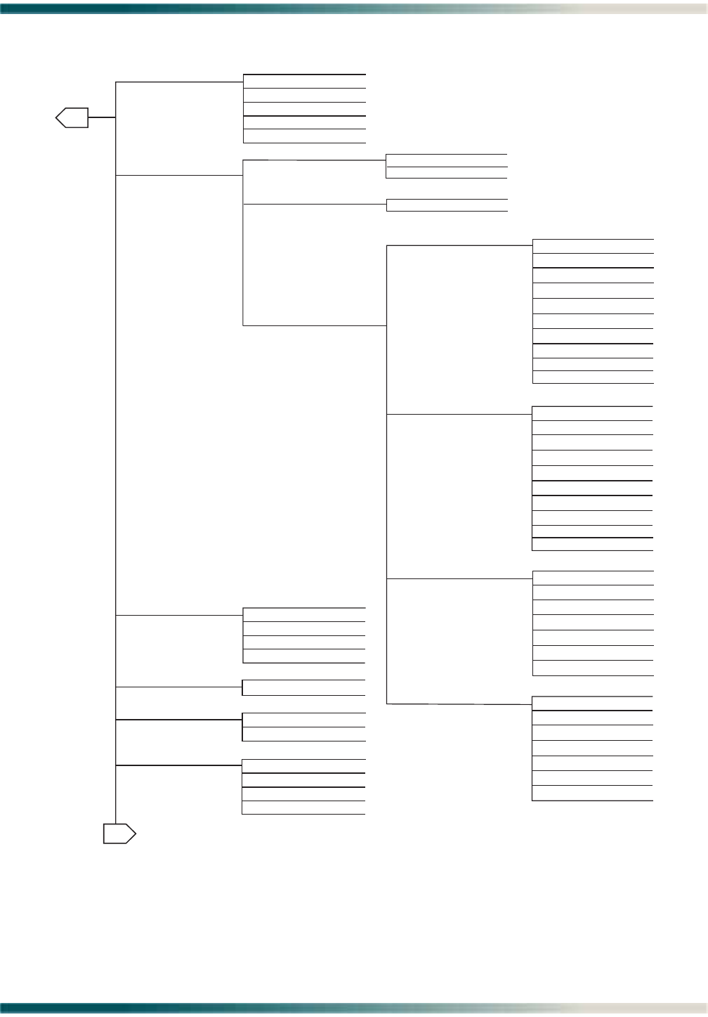
Menu Tree
61179641L4-5B 5-11
Figure 5-4. System Management Menu Tree
1. Set Passwords
2. Allow SNMP Security Management
3. Set Menus Idle Logout Time
5. Set TL1 Inband Idle Logout Time
4. Set TL1 Menus Idle Logout Time
6. Restore Default Passwords
1. IP Address
2. Ping Timeout
3. Number of Pings
4. Start Ping
IP Feed
2. Mode
3. Configure IP
1. Static
2. Dynamic
1. 9600
2. 19200
3. 38400
1. Adjust Time
2. Adjust Date
1. Password Control
2. IP Address
3. Test IP Address
4. Time/Date
5. Baud Rate
6. TFTP Configuration
Upload/Download
2. Subnet Mask
5. Default Gateway
Mac Address
1. IP Address
6. TFTP IP Address
7. TL1 Port Number (Set > 1023)
8. TL1 IP Transport Type
9. Reset IP Factory Defaults
Static IP Settings for IP over ATM
Dynamic IP Settings for IP over ATM
B
5. Start Traceroute
3. VPI/VCI
4. PCR
Subnet Mask
Default Gateway
Mac Address
IP Address
6. TFTP IP Address
7. TL1 Port Number (Set > 1023)
8. TL1 IP Transport Type
9. Reset IP Factory Defaults
3. VPI/VCI
4. PCR
Encapsulation is via rfc1483 SNAP
Encapsulation is via rfc1483 SNAP
TFTP Server
TFTP Function
TFTP Filename
Error Status
A
1. RFC1483 Routed
2. IP over Ethernet
Dynamic IP Settings for IP over Ethernet Subnet Mask
Default Gateway
Mac Address
IP Address
4. TFTP IP Address
5. TL1 Port Number (Set > 1023)
6. TL1 IP Transport Type
7. Reset IP Factory Defaults
2. Subnet Mask
3. Default Gateway
Mac Address
1. IP Address
4. TFTP IP Address
5. TL1 Port Number (Set > 1023)
6. TL1 IP Transport Type
7. Reset IP Factory Defaults
Static IP Settings for IP over Ethernet
Update Progress
3. RFC1483 Bridged
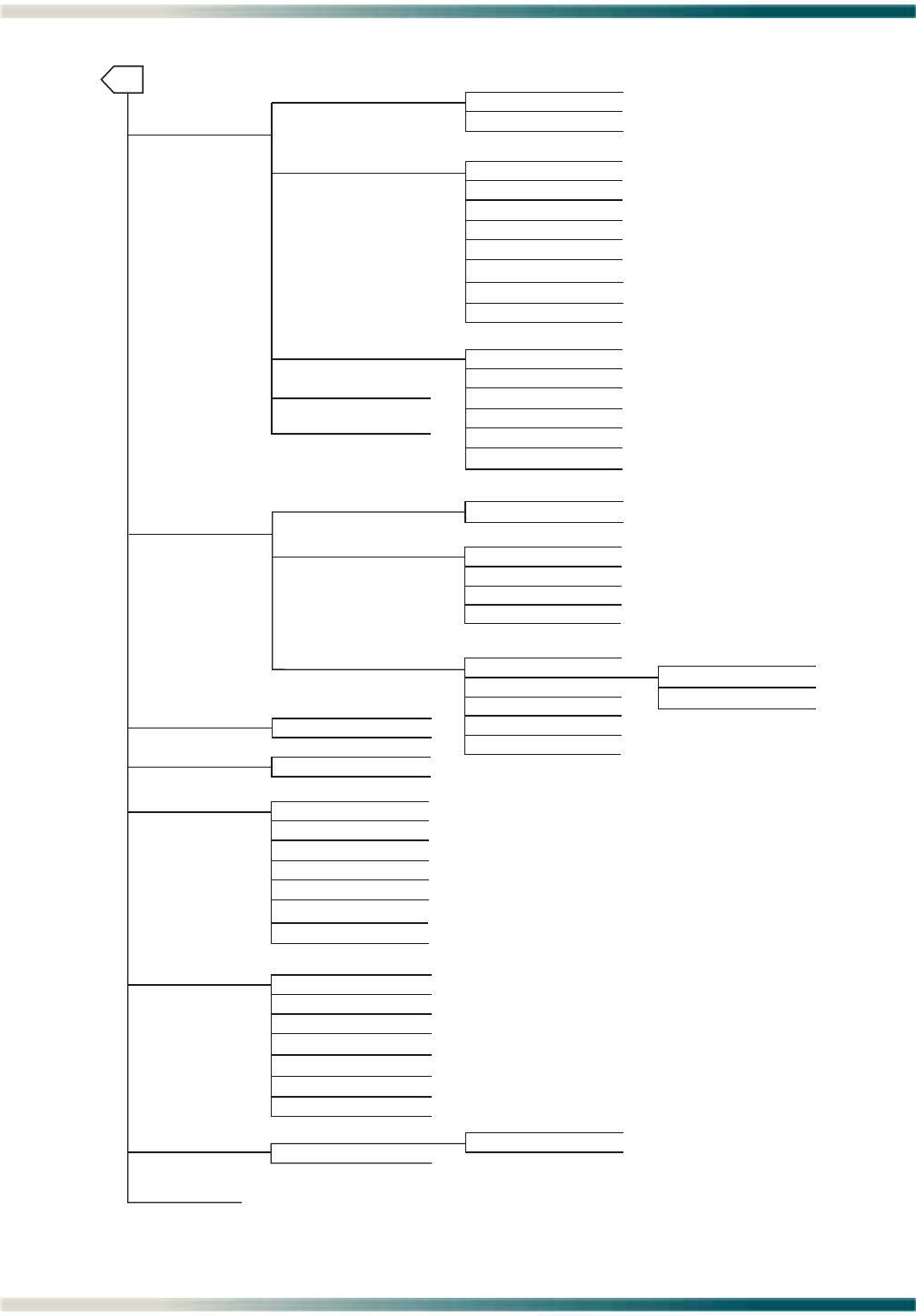
Total Access 1248 Octal T1 IMA DSLAM Installation and Maintenance Practice
5-12 61179641L4-5B
Figure 5-4. System Management Menu Tree (Continued)
B
13. Expansion Menu
12. External Alarms
1. Mode
2. Clear Packet Counts
System Uptime
2. Alarm #2
1. Alarm #1
3. Alarm #3
4. Severity
5. Severity
6. Severity
7. Fan Alarm Delay
1. Enabled
2. Disabled
1. IP Address
2. Version
3. IP Address
4. Version
5. IP Address
6. Version
7. Trap Port
1. Contact Information
2. Community Names
3. Trap Hosts
4. Traps Enabled
2. TFTP
2. Exit
7. SNMP/TL1
1. Download Network Module Code
1. Y-Modem
8. Download New Code
11. Self Test Results
10. Reset System
9. Restore Factory Defaults
5. TL1 Target ID
1. Restore
2. Exit
1. Contact
2. Name
3. Location
1. Name
2. IP Address
3. Privileges
4. Name
5. IP Address
6. Pivileges
7. Name
8. IP Address
9. Privileges
TFTP Server
TFTP Function
TFTP Filename
Error Status
Update Progress
1. Reset
2. Exit
1. Run Fan Self Test
Fan #1 Test
Fan #2 Test
Fan #3 Test
Fan #4 Test
ROM Test
RAM Test
EEPROM Test
1. AUC Config File
2. AUC Mode
3. AUC Refresh Interval
4. AUC Upgrade Retries
5. AUC TFTP Server
3. Auto Firmware Upgrade Provisioning
3. Disable
1. Auto
2. Manual
8. Restore External Alarm Defaults
6. AUC Base Path
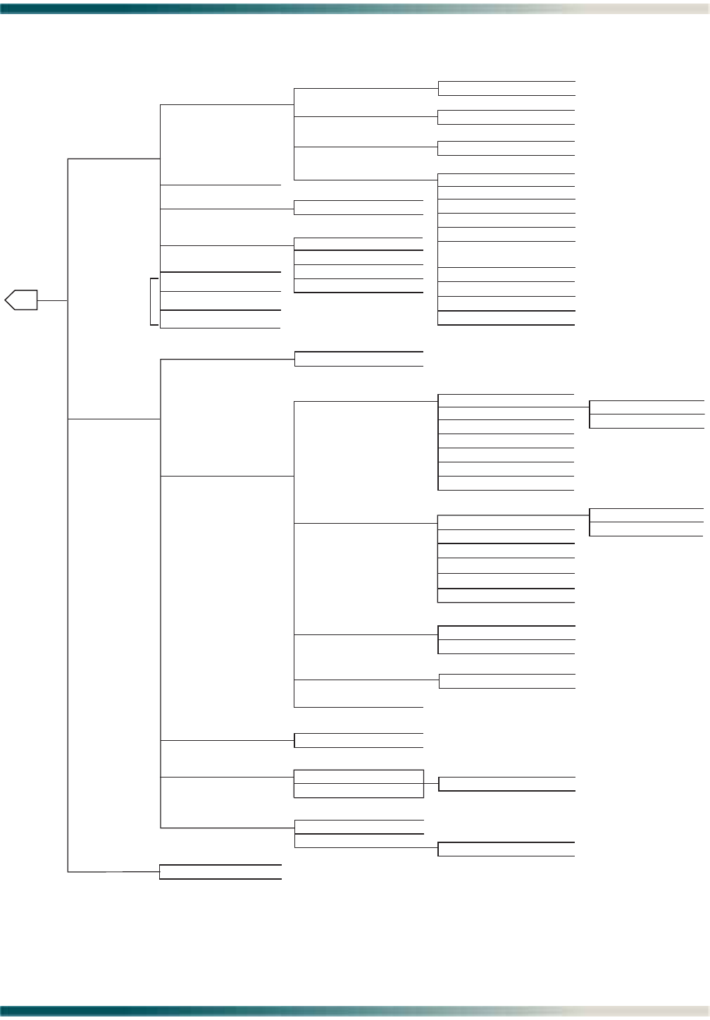
Menu Tree
61179641L4-5B 5-13
Figure 5-5. Network Port Menu Tree
1. T1/E1 Provisioning
2. T1/E1 Status
3. T1/E1 Performance
1. IMA Configuration
2. Framing (T1/E1)
3. Line Code (T1/E1)
1. IMA Group PM
2. Facilities PM
3. Clear All IMA Links PM
IMA Firmware Revision
IMA Link Type
2. IMA
1. Enable
2. Disable
2. Provisioning
3. Status/Failure Monitoring
4. Test
1. Force All Facilities Into Unassigned
2. Force Facility - 1 Into Pass Through
3. Force All Facilities Into IMA Group 1
1. Data Lpbk Towards Network
2. ATM Lpbk Towards Network
3. ATM Lpbk Towards Customer
Receive Group
Receive Link ID
Receive ATM Address
Transmit Group
Transmit Link ID
Transmit ATM Address
1. All Facilities Summary
2. Facility Operation Mode
IMA Transmit ID (0-255)
1. Group Operation Mode
IMA TX Frame Length (32, 64, 128, 256)
Min. TX Active Links
Min. RX Active Links
Max Link Diff. Delay <0-100>
Group Version Version 1.1
1. IMA Facility
2. IMA Group
3. Shortcut Setup
4. Scrambler
5. Restore Factory Defaults
1. Group FM Status
2. All Links FM Status
1. Type (T1 only)
4. Line Build Out (T1 only)
5. Performance Monitoring Data
1. T1/E1
1. DSX
2. T1
1. ESF (E1 option FAS+CRC)
2. SF (E1 option FAS)
1. B8ZS (E1 option HDB3)
2. AMI (E1 option AMI)
2. 133-266 feet
3. 266-399 feet
4. 399-533 feet
5. 533-655 feet
T1 Type
1. 0 dB
DSX Type
1. 0-133 feet
3. -15 dB
4. -22.5 dB
2. -7.5 dB
3. Select T1/E1 Mode 1. T1
2. E1
4. Test
5. Restore T1/E1 Factory Defaults
2. Line Loopback
3. Local Loopback
4. No Loopback
5. Clear T1/E1 Loopbacks On All Ports
1. Payload Loopback
1. Enable
2. Disable
1. T1/E1 PM
2. Clear All T1/E1 PM
C
1. IMA_Group
2. Unassigned
3. Pass Thru
1. In Service
2. Out of Service - Maintenance
3. Out of Service - Unassigned
1. Yes
2. No
6. SNMP/Menu Loopback Detection
7. Inband Loopback Detection
8. FDL Loopback Detection
T1 Only
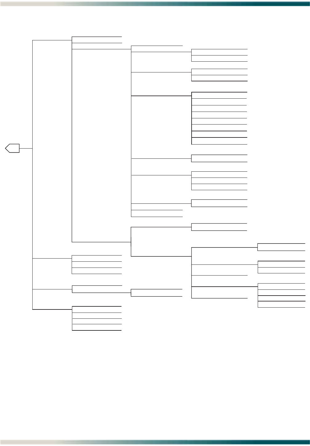
Total Access 1248 Octal T1 IMA DSLAM Installation and Maintenance Practice
5-14 61179641L4-5B
Figure 5-6. DSL Menu Tree
1. ADSL Provisioning
2. ADSL Status
3. ADSL Performance 1. Display PM for Current Port
2. Clear All PM for All Ports
1. ADSL Status
2. All ADSL Ports Status
3. ATU-R Information
4. BAT/SNR Tables
1. DSL Profiles
2. Alarm Profiles
3. Port Provisioning
4. Restore ADSL Provisioning
1. Select Port
2. ADSL Card Service State
3. Line Service State
6. Cabinet Mode
7. Link Down Alarm
8. Ports to apply changes
9. Apply Provisioning to all Ports
4. Service Mode
5. Hamband Mask
D
1. In Service
2. Out of Service - Unassigned
3. Out of Service - Maintenance
1. In Service
2. Out of Service - Unassigned
3. Out of Service - Maintenance
1. Multimode (ADSL1, ADSL2, ADSL2+)
2. T1.413
3. G.dmt
6. ADSL2.lite
7. ADSL2+
8. READSL
9. Legacy Multimode (ADSL1)
4. G.lite
5. ADSL2
1. Enabled
2. Disabled
1. Disabled
2. Enabled (Tone 250)
3. Enabled (Tone 110)
4. Enabled (Tone 130)
1. Enabled
2. Disabled
1. ADSL Provisioning Restore
2. DSP Management Menu
1. Yes
2. No
1. Reset
2. Exit
1. Reset All DSPs and Reload
Firmware
2. Reset DSPs without reloading
Firmware
3. Auto Warm Start
5. Exit
1. Reset
2. Exit
1. DSP:
2. Reset this DSP
3. Exit
4. Retrain Criteria
1. Retrain Margin NE
2. Retrain Margin FE
3. Retrain UAS-LNE
4. Retrain UAS-LFE
5. Retrain SES-FE
1. Port
2. Activate DELT
3. Terminate Test
4. Test Data Filename
5. DELT TFTP Address
4. DELT menus

Menu Descriptions
61179641L4-5B 5-15
MENU DESCRIPTIONS
Main Menu
Main Menu\
The Total Access 1248 Main menu (see Figure 5-7) is the access point to all other operations.
The Main menu options have several functions and submenus that identify and provide
access to specific operations and parameters.
Figure 5-7. Total Access 1248 Main Menu
The Total Access 1248 Main menu options are shown in Table 5-3.
Table 5-3. Total Access 1248 Main Menu Options
Option Description Function
1Configuration This option displays the “Configuration Screen” on
page 5-17.
2ATM Circuit Management This option displays the “ATM Circuit Management
Menu” on page 5-18.
3System Management This option displays the “System Management Menu” on
page 5-47.
4Network Port This option displays the “Network Port Menu” on page 5-
91.
5DSL Menus This option displays the “DSL Menus” on page 5-136.
6System Alarms This option displays the “System Alarm Log Screen” on
page 5-169.
TID: TA1248 Total Access 1248 MM/DD/YY HH:MM
Unacknowledged Alarms: None
Total Access 1248
1. Configuration
2. ATM Circuit Management
3. System Management
4. Network Port
5. DSL Menus
6. System Alarms
7. System Event Log
8. Contact Information
9. Enter TL1 mode
10. Logoff
Selection :
'?' - System Help Screen

Total Access 1248 Octal T1 IMA DSLAM Installation and Maintenance Practice
5-16 61179641L4-5B
7System Event Log This option displays the “System Event Log Screen” on
page 5-170.
8Contact Information This option displays the “Contact Information Screen” on
page 5-172.
9Enter TL1 Mode This option displays the “TL1 Mode Screen” on page 5-
173.
10 Logoff This option is used to end a Total Access 1248 menu
session.
Table 5-3. Total Access 1248 Main Menu Options (Continued)
Option Description Function

Menu Descriptions
61179641L4-5B 5-17
Configuration Screen
Configuration
Main Menu\Configuration\
The Configuration screen (see Figure 5-8) displays information about the system. For
instance, the CLEI Code and Part Number can be used to search for related information on the
ADTRAN web site or to order additional parts. The software revision may be required when
calling the ADTRAN Technical Support.
Figure 5-8. Configuration Screen
The Configuration screen fields are shown in Table 5-4.
Table 5-4. Configuration Screen Fields
Field Description
Unit Name This field displays the unit name of the Total Access 1248.
CLEI Code This field displays the Common Language Equipment Identifier
(CLEI) code of the Total Access 1248.
Part Number This field displays the part number of the Total Access 1248.
Serial Number This field displays the serial number of the Total Access 1248.
Production Revision This field displays the current product revision of the Total
Access 1248.
Software Revision This field displays the software revision of the Total Access
1248. This field updates automatically when a software
download is completed.
TID: TA1248 Total Access 1248 MM/DD/YY HH:MM
Unacknowledged Alarms: None
Configuration
Host
Unit Name TA1248
CLEI Code VAMBD00ARA
Part Number 1179641L4
Serial Number E46D0043
Product Revision H
Software Revision B03.06.01
'?' - System Help Screen

Total Access 1248 Octal T1 IMA DSLAM Installation and Maintenance Practice
5-18 61179641L4-5B
ATM Circuit Management Menu
ATM Circuit Management
Main Menu\ATM Circuit Management\
The ATM Circuit Management menu (see Figure 5-9) contains the steps used to provision and
maintain customer circuits. From this menu, a Permanent Virtual Circuit/Permanent Virtual
Path (PVC/PVP) for each ATM circuit can be viewed, created, or modified. PVCs are logical
connections between ports that allow data to be sent from the network to a customer location.
Figure 5-9. ATM Circuit Management Menu
The ATM Circuit Management menu options are shown in Table 5-5.
Table 5-5. ATM Circuit Management Menu Options
Option Description Function
1ATM PVC/PVP Management This option displays the “PVC/PVP Management Menu”
on page 5-19.
2ATM Traffic Parameter
Defaults
This option displays the “ATM Traffic Parameter Defaults
Screen” on page 5-35.
3Restore ATM defaults This option displays the “Restore ATM Factory Defaults
Menu” on page 5-36.
4ATM Performance This option displays the “ATM Performance Monitoring
Mode Menu” on page 5-38.
5ATM OAM Settings This option displays the “ATM OAM Settings Menu” on
page 5-44.
TID: TA1248 Total Access 1248 MM/DD/YY HH:MM
Unacknowledged Alarms: None
ATM Circuit Management
1. ATM PVC/PVP Management
2. ATM Traffic Parameter Defaults
3. Restore ATM defaults
4. ATM Performance
5. ATM OAM Settings
Selection :
'?' - System Help Screen

Menu Descriptions
61179641L4-5B 5-19
PVC/PVP Management Menu
PVC/PVP Management
Main Menu\ATM Circuit Management\PVC/PVP Management\
NOTE
If expansion mode is enabled (refer to “Expansion Menu” on
page 5-90), the Select Shelf menu (see Figure 5-10) displays. A host
or client unit must be chosen in order to access the PVC/PVP
Management menu.
Figure 5-10. Select Shelf Menu
The PVC/PVP Management menu (see Figure 5-11) is used to create, modify, view, or delete
PVCs.
NOTE
If there are no current PVCs, the PVC/PVP Management menu only
provides the create (C) hot key. In order to show all the available
hot key choices on the PVC/PVP Management menu, one PVC has
been created in Figure 5-11.
TID: TA1248 Total Access 1248 MM/DD/YY HH:MM
Unacknowledged Alarms: None
Select Shelf
1. Host
2. Client 1 (configured)
3. Client 2 (configured)
4. Client 3 (configured)
Selection :
'?' - System Help Screen

Total Access 1248 Octal T1 IMA DSLAM Installation and Maintenance Practice
5-20 61179641L4-5B
Figure 5-11. PVC/PVP Management Menu
The PVC/PVP Management hot keys are defined in Table 5-9.
Table 5-6. PVC/PVP Management Hot Keys
Hot Key Description Function
CCreate a new PVC/PVP This hot key displays the “Create a New PVC/PVP
Screen” on page 5-21.
DDelete a PVC/PVP This hot key displays the “Delete an Existing PVC/PVP
Screen” on page 5-23.
MModify a PVC/PVP This hot key displays the “Modify an Existing PVC/PVP
Screen” on page 5-24.
NDisplay next PVC/PVP page This hot key is used to display the next PVC/PVP page.
ODisplay ATM OAM statistics This hot key displays the “Current ATM OAM Statistics
Menu” on page 5-26.
PDisplay previous PVC/PVP
page
This hot key is used to display the previous PVC/PVP
page.
QDisplay quick provisioning
menu
This hot key displays the “ATM Quick Provisioning
Menu” on page 5-33.
VDisplay ATM PVC performance
menu
This hot key displays the “Current ATM PVC
Performance Menu” on page 5-31.
Page 1 of 1 PVC/PVP Management - Shelf: Host PVCs: 1
Endpoint 1 Endpoint 2
Circuit ID Port VPI VCI <-> Port VPI VCI
1 Netw 35 1000 1 0 35
Circuit ID:
Select: Endpoint2 -> Endpoint1
Service PCR(0+1) Pkt Discard
1 UBR Best Effort Enabled
Endpoint 1: Port VPI VCI Endpoint 2: Port VPI VCI
0 35 1000 1 0 35
Enter # or arrow keys to pick circuit; space bar for choices or c,d,m,n,o,p,v,q

Menu Descriptions
61179641L4-5B 5-21
Create a New PVC/PVP Screen
Create New PVC/PVP
Main Menu\ATM Circuit Management\PVC/PVP Management\Create New PVC/PVP\
The Create a New PVC/PVP screen (see Figure 5-12) is used to create the PVC/PVPs for ADSL
connections. Each ADSL connection has at least one PVC/PVP per ATM circuit provisioned for
data flow. PVC/PVPs map ATM circuits from the network to the ADSL ports.
Figure 5-12. Create a New PVC/PVP Screen
The Create a New PVC/PVP screen fields are shown in Table 5-7.
Table 5-7. Create a New PVC/PVP Screen Fields
Field Description
Endpoint 1 Port This field displays the network port.
Endpoint 1 VPI This field displays the Virtual Path Identifier for the ATM port
from the Network. Valid values range from 0 to 4095.
Endpoint 1 VCI This field displays the Virtual Channel Identifier for the ATM
port from the network. Valid values range from 0 to 65535.
Endpoint 2 Port This field displays the ATM port that is being created. Valid
values range from 1 to 48.
Endpoint 2 VPI This field displays the Virtual Path Identifier for the ATM port.
Valid values range from 0 to 4095.
Endpoint 2 VCI This field displays the Virtual Channel Identifier for the ATM.
Valid values range from 0 to 65535.
Create a New PVC/PVP
Endpoint 1 (Net --> Cust) Endpoint 2 (Net <-- Cust)
Port VPI VCI Port VPI VCI
Netw 35 1000 1 0 35
____________________________________________________________
Service Pkt Discard PCR
UBR Enabled Best Effort
Circuit ID
N/A
____________________________________________________________
When finished, place cursor here to select action:
Create new circuit and return to PVC/PVP Management
NOTE: No changes will take effect until an action is selected and executed.
To Select an action, place the cursor over the Action option and press the
Space Bar. To execute the action, press Enter.
Enter a VPI value between 0 an 4095.

Total Access 1248 Octal T1 IMA DSLAM Installation and Maintenance Practice
5-22 61179641L4-5B
Service This field identifies ATM Traffic Class. There are four service
options (Traffic Descriptors) available for the Total Access 1248
system:
•UBR
•CBR
•VBR-rt
•VBR-nrt
The options available for each service and their descriptions are
shown in Table 5-8.
Circuit ID This field displays the identifier given to a specific circuit. This
is a user defined value.
Pkt Discard This field displays the status of packet discard: Enabled or
Disabled.
Table 5-8. PVC/PVP Service Options
Service Description T1 Settings E1 Settings
UBR Unspecified bit rate
CBR
•PCR
Constant bit rate
• Peak Cell Rate 0-28976 0-38632
VBR-rt
•PCR
•SCR
•MBS
Variable bit rate real time
• Peak Cell Rate
• Sustained Cell Rate
•Maximum Burst Size
0-28976
0-28976
0-65535
0-38632
0-38632
0-65535
VBR-nrt
•PCR
•SCR
•MBS
Variable bit rate non-real time
• Peak Cell Rate
• Sustained Cell Rate
•Maximum Burst Size
0-28976
0-28976
0-65535
0-38632
0-38632
0-65535
Table 5-7. Create a New PVC/PVP Screen Fields (Continued)
Field Description

Menu Descriptions
61179641L4-5B 5-23
Delete an Existing PVC/PVP Screen
Delete Existing PVC/P VP
Main Menu\ATM Circuit Management\PVC/PVP Management\Delete Existing PVC/PVP
When the D hot key is selected to delete a PVC/PVP, a confirmation prompt at the bottom of
the screen (see Figure 5-13) displays.
Figure 5-13. Delete an Existing PVC/PVP Screen
Page 1 of 1 PVC/PVP Management - Shelf: Host PVCs: 1
Endpoint 1 Endpoint 2
Circuit ID Port VPI VCI <-> Port VPI VCI
1 Netw 35 1000 1 0 35
Circuit ID:
Select: Endpoint2 -> Endpoint1
Service PCR(0+1) Pkt Discard
1 UBR Best Effort Enabled
Endpoint 1: Port VPI VCI Endpoint 2: Port VPI VCI
0 35 1000 1 0 35
Delete this circuit (y/n)?

Total Access 1248 Octal T1 IMA DSLAM Installation and Maintenance Practice
5-24 61179641L4-5B
Modify an Existing PVC/PVP Screen
Modify Existing PVC/PVP
Main Menu\ATM Circuit Management\PVC/PVP Management\Modify Existing PVC/PVP\
The Modify an Existing PVC/PVP screen (see Figure 5-14) is used to modify existing PVC/
PVPs.
Figure 5-14. Modify an Existing PVC/PVP Screen
The Modify an Existing PVC/PVP screen fields are shown in Table 5-9.
Table 5-9. Modify an Existing PVC/PVP Screen Fields
Field Description
Endpoint 1 Port This field displays the network port.
Endpoint 1 VPI This field displays the Virtual Path Identifier for the ATM port
from the Network. Valid values range from 0 to 4095.
Endpoint 1 VCI This field displays the Virtual Channel Identifier for the ATM
port from the network. Valid values range from 0 to 65535.
Endpoint 2 Port This field displays the ATM port that is being created. Valid
values range from 1 to 48.
Endpoint 2 VPI This field displays the Virtual Path Identifier for the ATM port.
Valid values range from 0 to 4095.
Endpoint 2 VCI This field displays the Virtual Channel Identifier for the ATM.
Valid values range from 0 to 65535.
Modify an Existing PVC/PVP
Endpoint 1 (Net --> Cust) Endpoint 2 (Net <-- Cust)
Port VPI VCI Port VPI VCI
Netw 35 1000 1 0 35
____________________________________________________________
Service Pkt Discard PCR
UBR Enabled Best Effort
Circuit ID
N/A
____________________________________________________________
When finished, place cursor here to select action:
Modify existing circuit and return to PVC/PVP Management
NOTE: No changes will take effect until an action is selected and executed.
To Select an action, place the cursor over the Action option and press the
Space Bar. To execute the action, press Enter.
Enter a VPI value between 0 and 4095.

Menu Descriptions
61179641L4-5B 5-25
Service This field identifies ATM Traffic Class. There are four service
options (Traffic Descriptors) available for the Total Access 1248
system:
•UBR
•CBR
•VBR-rt
•VBR-nrt
The options available for each service and their descriptions are
shown in Table 5-10.
Circuit ID This field displays the identifier given to a specific circuit. This
is a user defined value.
Pkt Discard This field displays the status of packet discard: Enabled or
Disabled.
Table 5-10. PVC/PVP Service Options
Service Description T1 Settings E1 Settings
UBR Unspecified bit rate
CBR
•PCR
Constant bit rate
• Peak Cell Rate 0-28976 0-38632
VBR-rt
•PCR
•SCR
•MBS
Variable bit rate real time
• Peak Cell Rate
• Sustained Cell Rate
•Maximum Burst Size
0-28976
0-28976
0-65535
0-38632
0-38632
0-65535
VBR-nrt
•PCR
•SCR
•MBS
Variable bit rate non-real time
• Peak Cell Rate
• Sustained Cell Rate
•Maximum Burst Size
0-28976
0-28976
0-65535
0-38632
0-38632
0-65535
Table 5-9. Modify an Existing PVC/PVP Screen Fields (Continued)
Field Description

Total Access 1248 Octal T1 IMA DSLAM Installation and Maintenance Practice
5-26 61179641L4-5B
Current ATM OAM Statistics Menu
Current ATM OAM Statistics
Main Menu\ATM Circuit Management\PVC/PVP Management\Current ATM OAM Statistics\
The Current ATM Operations and Maintenance (OAM) Statistics menu (see Figure 5-15)
displays the network and line side OAM information for each ATM circuit.
OAM is the group of network management functions that provide network fault indication and
performance information.
Figure 5-15. Current ATM OAM Statistics Menu
The Current ATM OAM Statistics menu options are shown in Table 5-11.
Table 5-11. Current ATM OAM Statistics Menu Options
Option Description Function
1OAM Loopback Test Screen This option displays the “OAM Loopback Test Menu” on
page 5-28.
2Clear Current PVC OAM Stats This option clears the currently displayed PVC OAM
statistics.
3Clear All PVC OAM Stats This option clears all PVCs OAM statistics.
TID: TA1248 Total Access 1248 MM/DD/YY HH:MM
Unacknowledged Alarms: None
Current ATM OAM Statistics
Endpoint 1 Endpoint 2 Modem Status
Port VPI VCI Port VPI VCI Down
0 35 1000 1 0 35
Endpoint 1 (Net --> Cust) Endpoint 2 (Net <-- Cust)
Rx OAM Cells : 0 Rx OAM Cells : 0
AIS State : FALSE AIS State : FALSE
RDI State : FALSE RDI State : FALSE
1. OAM Loopback Test Screen
2. Clear Current PVC OAM Stats
3. Clear All PVC OAM Stats
Selection :
'N' - Next PVC 'P' - Previous PVC 'S' - Select PVC

Menu Descriptions
61179641L4-5B 5-27
The Current ATM OAM Statistics menu fields are shown in Table 5-12.
Table 5-12. Current ATM OAM Statistics Menu Fields
Field Description
Endpoint 1
Rx OAM Cells This field displays the total number of received OAM cells for
Endpoint 1.
AIS State This field indicates if the Endpoint is in AIS state (True) or not
(False).
RDI State This field indicates if the Endpoint is in the RDI state (True) or
not (False).
Endpoint 2
Rx OAM Cells This field displays the total number of received OAM cells for
Endpoint 2.
AIS State This field indicates if the Endpoint is in AIS state (True) or not
(False).
RDI State This field indicates if the Endpoint is in the RDI state (True) or
not (False).

Total Access 1248 Octal T1 IMA DSLAM Installation and Maintenance Practice
5-28 61179641L4-5B
OAM Loopback Test Menu
OAM Loopback Test
Main Menu\ATM Circuit Management\PVC/PVP Management\Current ATM OAM Statistics\OAM Loopback Test\
The OAM Loopback Test menu (see Figure 5-16) displays the network and line side infor-
mation for each ATM circuit.
Figure 5-16. OAM Loopback Test Menu
The OAM Loopback Test menu options are shown in Table 5-13.
Table 5-13. OAM Loopback Test Menu Options
Option Description Function
1Endpoint 1 Remote OAM
Loopback Location ID
This option is used to enter the Endpoint 1 remote
loopback location ID. The remote loopback location ID is
in hexadecimal 16 byte format.
2Endpoint 2 Remote OAM
Loopback Location ID
This option is used to enter the Endpoint 2 remote
loopback location ID. The remote loopback location ID is
in hexadecimal 16 byte format.
3Type of OAM Loopback Cell This option is used to specify the type of OAM Loopback
cell. Options include the following:
•Segment
•End-to-End
TID: TA1248 Total Access 1248
Unacknowledged Alarms: None
OAM Loopback Test
Endpoint 1 Endpoint 2 Modem Status
Port VPI VCI Port VPI VCI Down
0 35 1000 1 0 35
Endpoint 1 (Net --> Cust) Endpoint 2 (Net <-- Cust)
Tx Loopback Request : 0 Tx Loopback Request : 0
Rx Loopback Request : 0 Rx Loopback Request : 0
Tx Loopback Response : 0 Tx Loopback Response : 0
Rx Loopback Response : 0 Rx Loopback Response : 0
Loopback Passed : 0 Loopback Passed : 0
Loopback Failed : 0 Loopback Failed : 0
1. Endpoint 1 Remote OAM Loopback Location ID : FFFFFFFFFFFFFFFFFFFFFFFFFFFFFFFF
2. Endpoint 2 Remote OAM Loopback Location ID : FFFFFFFFFFFFFFFFFFFFFFFFFFFFFFFF
3. Type of OAM Loopback Cell : Segment
4. Send from Endpoint 1 to Network
5. Send from Endpoint 2 to Customer
6. Reset Loopback Statistics
Selection :

Menu Descriptions
61179641L4-5B 5-29
The OAM Loopback Test menu fields are shown in Table 5-14.
4Send from Endpoint 1 to
Network
This option is used to initiate a loopback from Endpoint
1 to the network.
5Send from Endpoint 2 to
Customer
This option is used to initiate a loopback from Endpoint
2 to the customer.
6Reset Loopback Statistics This option clears the loopback statistics for this circuit.
Table 5-14. OAM Loopback Test Menu Fields
Field Description
Endpoint 1
Port This field displays the physical port.
VPI This field displays the VPI for Endpoint 1.
VCI This field displays the VCI for Endpoint 1.
Endpoint 2
Port This field displays the physical port.
VPI This field displays the VPI for Endpoint 2.
VCI This field displays the VCI for Endpoint 2.
Endpoint 1 (Net --> Cust)
Tx Loopback Request This field displays the total number of transmitted loopback
requests.
Rx Loopback Request This field displays the total number of received loopback
requests.
Tx Loopback Response This field displays the total number of transmitted loopback
responses.
Rx Loopback Response This field displays the total number of received loopback
responses.
Loopback Passed This field displays the total number of loopback request that
passed.
Loopback Failed This field displays the total number of loopback request that
failed.
Endpoint 2 (Net <-- Cust)
Tx Loopback Request This field displays the total number of transmitted loopback
requests.
Rx Loopback Request This field displays the total number of received loopback
requests.
Table 5-13. OAM Loopback Test Menu Options (Continued)
Option Description Function

Total Access 1248 Octal T1 IMA DSLAM Installation and Maintenance Practice
5-30 61179641L4-5B
Tx Loopback Response This field displays the total number of transmitted loopback
responses.
Rx Loopback Response This field displays the total number of received loopback
responses.
Loopback Passed This field displays the total number of loopback request that
passed.
Loopback Failed This field displays the total number of loopback request that
failed.
Modem Status This field displays the modem status.
Table 5-14. OAM Loopback Test Menu Fields (Continued)
Field Description

Menu Descriptions
61179641L4-5B 5-31
Current ATM PVC Performance Menu
Current ATM PVC Performance
Main Menu\ATM Circuit Management\PVC/PVP Management\Current ATM PVC Performance\
The Current ATM PVC Performance menu (see Figure 5-17) displays the network and port side
information for each ATM circuit.
Figure 5-17. Current ATM PVC Performance Menu
The Current ATM PVC Performance menu options are shown in Table 5-15.
The Current ATM PVC Performance menu fields are shown in Table 5-16.
Table 5-15. Current ATM PVC Performance Menu Options
Option Description Function
1Clear Current PVC PM This option clears the currently displayed PVC
performance monitoring statistics.
2Clear All PVC PM This option clears all the PVCs performance monitoring
statistics.
TID: TA1248 Total Access 1248 MM/DD/YY HH:MM
Unacknowledged Alarms: None
Current ATM PVC Performance
Endpoint 1 Endpoint 2 Modem Status
Port VPI VCI Port VPI VCI Down
0 35 1000 1 0 35
Endpoint 1 (Net --> Cust) Endpoint 2 (Net <-- Cust)
Tx Cells : 0 Tx Cells : 0
Discarded Queue Full : 0 Discarded Queue Full : 0
Cells/Sec (Last Sec) : 0 Cells/Sec (Last Sec) : 0
Cells/Sec (60 Sec Avg): 0 Cells/Sec (60 Sec Avg): 0
1. Clear Current PVC PM
2. Clear All PVC PM
Selection :
'N' - Next PVC 'P' - Previous PVC 'S' - Select PVC
'?' - System Help Screen

Total Access 1248 Octal T1 IMA DSLAM Installation and Maintenance Practice
5-32 61179641L4-5B
Table 5-16. Current ATM Port Performance Menu Fields
Field Description
Endpoint 1 (Net --> Cust)
Tx Cells This field displays the total number of transmit cells for
Endpoint 1 for the current performance period.
Discarded Queue Full This field displays the number of cells discarded for Endpoint 1
because of a full queue.
Cells/Sec (Last Sec) This field displays the number of cells transmitted per second
for Endpoint 1.
Cells/Sec (60 Sec Avg) This field displays the average number of cells transmitted every
60 seconds for Endpoint 1.
Endpoint 2 (Net <-- Cust)
Tx Cells This field displays the total number of received cells for
Endpoint 2 for the current performance period.
Discarded Queue Full This field displays the number of cells discarded because of a
full queue.
Cells/Sec (Last Sec) This field displays the number of cells received per second for
Endpoint 2.
Cells/Sec (60 Sec Avg) This field displays the average number of cells received every 60
seconds for Endpoint 2.

Menu Descriptions
61179641L4-5B 5-33
ATM Quick Provisioning Menu
ATM Quick Provisioning
Main Menu\ATM Circuit Management\PVC/PVP Management\ATM Quick Provisioning\
The ATM Quick Provisioning menu (see Figure 5-18) is used to quickly create ATM circuits
based on reference circuits.
Figure 5-18. ATM Quick Provisioning Menu
The ATM Quick Provisioning menu options are described in Table 5-17. Note that options are
dependent on each other.
Figure 5-19 shows the ATM PVC/PVP Management menu after creating new ATM circuits
using the ATM Quick Provisioning menu with the settings shown in Figure 5-18.
Table 5-17. ATM Quick Provisioning Menu Options
Option Description Function
1Increment Endpoint 1 VPI This option increments the Endpoint 1 VPI value by one.
2Increment Endpoint 1 VCI This option increments the Endpoint 1 VCI value by one.
3Increment Endpoint 2 Port This option increments the Endpoint 2 Port value by
one.
4Increment Endpoint 2 VPI This option increments the Endpoint 2 VPI value by one.
5Increment Endpoint 2 VCI This option increments the Endpoint 2 VCI value by one.
6Number of Circuits to Create This option is used to indicate the number of circuits to
be created.
7Create New ATM Circuits This option is used to create the new ATM circuit.
TID: TA1248 Total Access 1248
Unacknowledged Alarms: None
ATM Quick Provisioning
Endpoint 1 Endpoint 2
Port VPI VCI Port VPI VCI
Netw 35 1000 1 0 35
Type Pkt Discard PCR
UBR Enabled Best Effort
1. Increment Endpoint 1 VPI? NO
2. Increment Endpoint 1 VCI? YES
3. Increment Endpoint 2 Port? YES
4. Increment Endpoint 2 VPI? NO
5. Increment Endpoint 2 VCI? NO
6. Number of Circuits to Create: 47
7. Create New ATM Circuits.
Selection :
This screen allows quick creation of ATM circuits based on the reference circuit
above. All the highlighted attributes will increment by one 47 times.
'?' - System Help Screen

Total Access 1248 Octal T1 IMA DSLAM Installation and Maintenance Practice
5-34 61179641L4-5B
Figure 5-19. ATM PVC/PVP Management Menu with 48 PVCs
Page 1 of 5 PVC/PVP Management - Shelf: Host PVCs: 48
Endpoint 1 Endpoint 2
Circuit ID Port VPI VCI <-> Port VPI VCI
1 Netw 35 1000 1 0 35
2 Netw 35 1001 2 0 35
3 Netw 35 1002 3 0 35
4 Netw 35 1003 4 0 35
5 Netw 35 1004 5 0 35
6 Netw 35 1005 6 0 35
7 Netw 35 1006 7 0 35
8 Netw 35 1007 8 0 35
9 Netw 35 1008 9 0 35
10 Netw 35 1009 10 0 35
11 Netw 35 1010 11 0 35
12 Netw 35 1011 12 0 35
Circuit ID:
Select: Endpoint2 -> Endpoint1
Service PCR(0+1) Pkt Discard
3 UBR Best Effort Enabled
Endpoint 1: Port VPI VCI Endpoint 2: Port VPI VCI
0 35 1002 3 0 35
Enter # or arrow keys to pick circuit; space bar for choices or c,d,m,n,o,p,v,q

Menu Descriptions
61179641L4-5B 5-35
ATM Traffic Parameter Defaults Screen
ATM Traffic Parameter Defaults
Main Menu\ATM Circuit Management\ATM Traffic Parameter Defaults
The ATM Traffic Parameter Defaults screen (see Figure 5-20) displays the system defaults for
the ATM circuits. Traffic parameters represent priorities given to ATM cell transmissions.
Once traffic parameters are set from this screen, all PVC/PVPs provisioned from that point
forward will use these parameter defaults.
Figure 5-20. ATM Traffic Parameter Defaults Screen
The ATM Traffic Parameters Defaults screen Traffic Types are shown in Table 5-18.
Table 5-18. ATM Parameters Defaults Screen Traffic Types
Traffic Type Definition
PCR The Peak Cell Rate designates an upper limit that the traffic
information rate cannot exceed.
SCR The Sustainable Cell Rate specifies the average traffic rate that
is transmitted and received.
MCR The Minimum Cell Rate designates a minimum limit that the
traffic information rate cannot fall below.
MBS The Maximum Burst Size specifies the maximum number of
cells per second (CPS) that can be transmitted at the PCR.
TID: TA1248 Total Access 1248
Unacknowledged Alarms: None
ATM Traffic Parameter Defaults
Endpoint 2 -> Endpoint 1
Traffic Type PCR(0+1) SCR(0+1) MCR(0+1) MBS(0+1)
UBR Best Effort N/A N/A N/A
CBR 0 N/A N/A N/A
VBR-rt 0 0 N/A 0
VBR-nrt 0 0 N/A 0
Traffic Type Pkt Discard
UBR Enabled
CBR Enabled
VBR-rt Enabled
VBR-nrt Enabled
Note: This screen allows modification of the DEFAULT traffic parameter settings,
which can be overridden on a per PVC/PVP basis in the PVC/PVP Management menu.

Total Access 1248 Octal T1 IMA DSLAM Installation and Maintenance Practice
5-36 61179641L4-5B
Restore ATM Factory Defaults Menu
Restore ATM Factory Defaults
Main Menu\ATM Circuit Management\Restore ATM Factory Defaults\
The Total Access 1248 provisioning system provides the ability to restore the ATM parameters
to the factory defaults. Figure 5-21 displays the Restore ATM Factory Defaults menu.
Figure 5-21. Restore ATM Factory Defaults Menu
CAUTION
This action is service affecting. All traffic descriptors and PVCs are
removed.
The Restore ATM Factory Defaults menu options are shown in Table 5-19.
TID: TA1248 Total Access 1248 MM/DD/YY HH:MM
Unacknowledged Alarms: None
Restore ATM Factory Defaults
WARNING! THIS IS SERVICE AFFECTING!
This is for defaulting the ATM parameters only. This
will delete all of the selected PVCs and reset the
traffic descriptors to their default values.
1. Delete All PVCs and Restore Default Settings
2. Delete Host PVCs
3. Delete Client 1 PVCs
4. Delete Client 2 PVCs
5. Delete Client 3 PVCs
Selection :
'?' - System Help Screen

Menu Descriptions
61179641L4-5B 5-37
Table 5-19. Restore ATM Factory Defaults Menu Options
Option Description Function
1Delete All PVCs and Restore
Default Settings
This option deletes all PVCs and restores ATM factory
defaults without additional prompting.
2Delete Host PVCs This option deletes Host PVCs without additional
prompting.
3Delete Client 1 PVCs This option deletes Client 1 PVCs without additional
prompting, if enabled.
4Delete Client 2 PVCs This option deletes Client 2 PVCs without additional
prompting, if enabled.
5Delete Client 3 PVCs This option deletes Client 3 PVCs without additional
prompting, if enabled.

Total Access 1248 Octal T1 IMA DSLAM Installation and Maintenance Practice
5-38 61179641L4-5B
ATM Performance Monitoring Mode Menu
ATM Performance Monitoring Mode
Main Menu\ATM Circuit Management\ATM Performance Monitoring Mode\
NOTE
If expansion mode is enabled (refer to “Expansion Menu” on
page 5-90), the Select Shelf menu (see Figure 5-22) displays. A host
or client unit must be chosen in order to access the ATM
Performance Monitoring Mode menu.
Figure 5-22. Select Shelf Menu
The Total Access 1248 tracks performance statistics for ATM ports via the ATM Performance
Monitoring Mode menu (see Figure 5-23).
TID: TA1248 Total Access 1248 MM/DD/YY HH:MM
Unacknowledged Alarms: None
Select Shelf
1. Host
2. Client 1 (configured)
3. Client 2 (configured)
4. Client 3 (configured)
Selection :
'?' - System Help Screen

Menu Descriptions
61179641L4-5B 5-39
Figure 5-23. ATM Performance Monitoring Mode Menu
The ATM Performance Monitoring Mode menu options are shown in Table 5-20.
Table 5-20. ATM Performance Monitoring Mode Menu Options
Option Description Function
1Change ATM Port Number This option is used to change the ATM port number
without additional prompting. The current port number
is displayed above the menu items on the ATM
Performance Monitoring Mode menu.
2ATM Performance Data This option displays the “ATM Performance Monitoring
Status Screen” on page 5-40.
3ATM Port Cell Count
Summary
This option displays the “ATM Port Cell Count Summary
Screen” on page 5-42.
4Clear All PM for All Ports This option displays the “Clear All PM for All Ports
Menu” on page 5-43.
TID: TA1248 Total Access 1248
Unacknowledged Alarms: None
ATM Performance Monitoring Mode
Port: Network
1. Change ATM Port Number Network
2. ATM Performance Data
3. ATM Port Cell Count Summary
4. Clear All PM for All Ports
Selection :
This screen allows you to view the ATM stats for a particular port.
Enter 0 for the network port or 1 - 48 for the customer ports.
'?' - System Help Screen

Total Access 1248 Octal T1 IMA DSLAM Installation and Maintenance Practice
5-40 61179641L4-5B
ATM Performance Monitoring Status Screen
ATM Performance Monitoring Status
Main Menu\ATM Circuit Management\ATM Performance Monitoring Mode\ATM Performance Monitoring Status\
The ATM Performance Monitoring Status screen (see Figure 5-24) displays the port perfor-
mance for the port selected. This menu lists the cell transmitted to the Network, cells trans-
mitted to the customer, discarded cells, and the HEC Error count for the selected performance
period.
Figure 5-24. ATM Performance Monitoring Status Screen
The ATM Performance Monitoring Status screen options are shown in Table 5-21.
Table 5-21. ATM Performance Monitoring Status Screen Fields
Field Description
Port This field displays the port number for the cell count summary.
TX (to net) This field displays the number of cells transmitted to the
network.
RX (to cust) This field displays the number of cells received from the
network and transmitted to the customer.
Discarded Cells This field displays the number of discarded cells.
HEC Error Cnt This field displays the HEC errors, which are Cyclical
Redundancy Check (CRC) errors in the last byte of the ATM cell
header used for checking integrity.
TID: TA1248 Total Access 1248 MM/DD/YY HH:MM
Unacknowledged Alarms: None
ATM Performance Monitoring Status
Shelf: HOST Port: Network
TX (to net) TX (to cust) Discarded Cells HEC Error Cnt
24 Hr - Current 0 0 0 0
MM/DD 0 0 0 0
Avg CPS (60s) 0 0
Current CPS 0 0
15 Min - Current 0 0 0 0
16:15 0 0 0 0
16:00 0 0 0 0
15:45 0 0 0 0
15:30 0 0 0 0
15:15 0 0 0 0
15:00 0 0 0 0
14:45 0 0 0 0
14:30 0 0 0 0
B - Backward(2hrs/15min PM)
S - Select Port P - Previous Port N - Next Port C - Clear PM Status
'?' - System Help Screen

Menu Descriptions
61179641L4-5B 5-41
The ATM Performance Monitoring Status hot keys are defined in Table 5-22.
Table 5-22. ATM Performance Monitoring Status Hot Keys
Hot Key Description Function
BBackward (2hrs/15min PM) This hot key is used to display performance monitoring
statistics for the last 2 hours, in 15 minute intervals.
CClear PM Status This hot key is used to clear the performance monitoring
statistics.
FForward (2hrs/15min PM) This hot key is used to display performance monitoring
statistics for the next 2 hours, in 15 minute intervals.
PPrevious Port This hot key is used to display the previous port.
NNext Port This hot key is used to display the next port.
SSelect Port This hot key is used to select a specific port.

Total Access 1248 Octal T1 IMA DSLAM Installation and Maintenance Practice
5-42 61179641L4-5B
ATM Port Cell Count Summary Screen
ATM Port Cell Count Summary
Main Menu\ATM Circuit Management\ATM Performance Monitoring Mode\ATM Port Cell Count Summary\
The ATM Port Cell Count Summary screen (see Figure 5-25) displays a summary of cell counts
for all ports simultaneously.
Figure 5-25. ATM Port Cell Count Summary Screen
The ATM Port Cell Count Summary screen fields are shown in Table 5-23.
Table 5-23. ATM Port Cell Count Summary Screen Fields
Field Description
Port This field displays the port number for the cell count summary.
Tx This field displays the number of cells transmitted to the
network.
Rx This field displays the number of cells received from the
network and transmitted to the customer.
Disc. This field displays the number of discarded cells.
TID: TA1248 Total Access 1248 MM/DD/YY HH:MM
Unacknowledged Alarms: None
ATM Port Cell Count Summary
Port Tx Rx Disc. Port Tx Rx Disc.
1 0 0 0 13 0 0 0
2 0 0 0 14 0 0 0
3 0 0 0 15 0 0 0
4 0 0 0 16 0 0 0
5 0 0 0 17 0 0 0
6 0 0 0 18 0 0 0
7 0 0 0 19 0 0 0
8 0 0 0 20 0 0 0
9 0 0 0 21 0 0 0
10 0 0 0 22 0 0 0
11 0 0 0 23 0 0 0
12 0 0 0 24 0 0 0
NOTE: Tx is to network, Rx is to customer, Disc. is discarded cells
Highlighted Port indicates the ADSL loop is trained.
'N' - Next Page
'?' - System Help Screen

Menu Descriptions
61179641L4-5B 5-43
Clear All PM for All Ports Menu
Clear All PM for All Ports
Main Menu\ATM Circuit Management\ATM Performance Monitoring Mode\Clear All PM for All Ports\
The Clear All PM for All Ports option is selected from the ATM Performance Monitoring Mode
Menu.
The Clear All PM for All Ports menu options are shown in Table 5-24.
Table 5-24. Clear All PM for All Ports Menu Options
Option Description Function
1Yes This option clears the performance monitoring data for
all of the ports.
2No This option returns the display to the “ATM Performance
Monitoring Mode Menu” on page 5-38 and does not clear
the performance monitoring data.

Total Access 1248 Octal T1 IMA DSLAM Installation and Maintenance Practice
5-44 61179641L4-5B
ATM OAM Settings Menu
ATM OAM Setti ngs
Main Menu\ATM Circuit Management\ATM OAM Settings\
The ATM OAM Settings menu (see Figure 5-26) is used to provision the Total Access 1248
OAM settings and to test the Inband channel PVC for an ATM fed system.
Figure 5-26. ATM OAM Settings Menu
The ATM OAM Settings menu options are shown in Table 5-25.
Table 5-25. ATM OAM Settings Menu Options
Option Description Function
1DSLAM OAM Loopback
Location ID
This is option is used to enter the loopback location ID
for the Total Access 1248. The remote loopback location
ID is in hexadecimal 16 byte format.
2DSLAM OAM State This option is used to toggle the Total Access 1248 OAM
state between Disabled and Enabled.
3Inband OAM Loopback Test This option displays the “Inband OAM Loopback Test
Menu” on page 5-45.
TID: TA1248 Total Access 1248
Unacknowledged Alarms: None
ATM OAM Settings
1. DSLAM OAM Loopback Location ID : FFFFFFFFFFFFFFFFFFFFFFFFFFFFFFFF
2. DSLAM OAM State : Disabled
3. Inband OAM Loopback Test
Selection :
'?' - System Help Screen

Menu Descriptions
61179641L4-5B 5-45
Inband OAM Loopback Test Menu
Inband OAM Loopback Test
Main Menu\ATM Circuit Management\ATM OAM Settings\Inband OAM Loopback Test\
The Inband OAM Loopback Test menu (see Figure 5-27) is used to provision the Total Access
1248 OAM Loopback settings and to test the Inband channel PVC for an ATM fed box.
Figure 5-27. Inband OAM Loopback Test Menu
The Inband OAM Loopback Test menu options are shown in Table 5-26.
The Inband OAM Loopback Test menu fields are shown in Table 5-27.
Table 5-26. Inband OAM Loopback Test Menu Options
Option Description Function
1Remote OAM Loopback
Location ID
This is option is used to enter the remote loopback
location ID. The remote loopback location ID is in
hexadecimal 16 byte format.
2Type of OAM Loopback Cell This option is used to specify the type of OAM Loopback
cell. Options include the following:
•Segment
•End-to-End
3Send Loopback Cell This option is used to send a loopback cell.
4Reset Loopback Statistics This option clears the OAM loopback statistics for this
circuit.
5Reset All Statistics This option clears all OAM loopback statistics.
TID: TA1248 Total Access 1248
Unacknowledged Alarms: None
Inband OAM Loopback Test
Port VPI VCI
0 0 32
Tx Loopback Request : 0 Rx OAM Cells : 0
Rx Loopback Request : 0 AIS State : FALSE
Tx Loopback Response : 0 RDI State : FALSE
Rx Loopback Response : 0
Loopback Passed : 0
Loopback Failed : 0
1. Remote OAM Loopback Location ID : FFFFFFFFFFFFFFFFFFFFFFFFFFFFFFFF
2. Type of OAM Loopback Cell : Segment
3. Send Loopback Cell
4. Reset Loopback Statistics
5. Reset All Statistics
Selection :
'?' - System Help Screen

Total Access 1248 Octal T1 IMA DSLAM Installation and Maintenance Practice
5-46 61179641L4-5B
Table 5-27. Inband OAM Loopback Test Menu Fields
Field Description
Port This field displays the physical port.
VPI This field displays the VPI for the circuit.
VCI This field displays the VCI for the circuit.
Tx Loopback Request This field displays the total number of transmitted loopback
requests.
Rx Loopback Request This field displays the total number of received loopback
requests.
Tx Loopback Response This field displays the total number of transmitted loopback
responses.
Rx Loopback Response This field displays the total number of received loopback
responses.
Loopback Passed This field displays the total number of loopback request that
passed.
Loopback Failed This field displays the total number of loopback request that
failed.
Rx OAM Cells This field displays the total number of received OAM cells.
AIS State This field indicates if the Endpoint is in AIS state (True) or not
(False).
RDI State This field indicates if the Endpoint is in the RDI state (True) or
not (False).

Menu Descriptions
61179641L4-5B 5-47
System Management Menu
System Management
Main Menu\System Management\
The System Management menu (see Figure 5-28) is used to manage system settings. The
following subsections describe these settings in detail.
Figure 5-28. System Management Menu
The System Management menu options are shown in Table 5-28.
Table 5-28. System Management Menu Options
Option Description Function
1Password Control This option displays the “Password Control Menu” on
page 5-49.
2IP Address This option displays the “Mode Selection and Current IP
Settings Menu” on page 5-52.
3Test IP Address This option displays the “Test IP Address Menu” on
page 5-66.
4Time/Date This option displays the “Time/Date Adjust Menu” on
page 5-67.
5Baud Rate This option displays the “Current Baud Rate Menu” on
page 5-68.
6TFTP Configuration Upload/
Download
This option displays the “TFTP Configuration Storage/
Retrieval Screen” on page 5-69.
TID: TA1248 Total Access 1248 MM/DD/YY HH:MM
Unacknowledged Alarms: None
System Management
1. Password Control
2. IP Address
3. Test IP Address
4. Time/Date
5. Baud Rate
6. TFTP Configuration Upload/Download
7. SNMP/TL1
8. Download New Code
9. Restore Factory Defaults
10. Reset System
11. Self Test Results
12. External Alarms
13. Expansion Menu
14. Modem Configuration
System Uptime: 2 hrs 33 mins 44 secs
Selection : '?' - System Help Screen

Total Access 1248 Octal T1 IMA DSLAM Installation and Maintenance Practice
5-48 61179641L4-5B
7SNMP/TL1 This option displays the “SNMP/TL1 Configuration
Menu” on page 5-71.
8Download New Code This option displays the “Code Download Method Menu”
on page 5-77.
9Restore Factory Defaults This option displays the “Restore Factory Defaults
Menu” on page 5-84.
10 Reset System This option displays the “Reset System Menu” on
page 5-85.
11 Self Test Results This option displays the “Self Test Menu” on page 5-86.
12 External Alarms This option displays the “External Alarms Menu” on
page 5-88.
13 Expansion Menu This option displays the “Expansion Menu” on page 5-
90.
N/A System Uptime This field displays the length of time the Total Access
1248 system has been running. Each time the system is
reset, this value resets to 0 days, 0 hours, 0 minutes,
and 0 seconds.
Table 5-28. System Management Menu Options (Continued)
Option Description Function

Menu Descriptions
61179641L4-5B 5-49
Password Control Menu
Password Control
Main Menu\System Management\Password Control\
The Password Control menu (see Figure 5-29) is used to set and modify passwords, logout
times, and restore default passwords. The system provides up to eleven user accounts.
Figure 5-29. Password Control Menu
The Password Control menu options are shown in Table 5-29.
Table 5-29. Password Control Menu Options
Option Description Function
1Set Passwords This option displays the “Password Control Levels
Screen” on page 5-50.
2Allow SNMP Security
Management
This option displays the “Allow SNMP Security
Management” on page 5-51.
3Set Menus Idle Logout Time This option displays the “Set Menus Idle Logout Time”
on page 5-51.\
4Set TL1 Menus Idle Logout
Time
This option displays the “Set TL1 Menus Idle Logout
Time” on page 5-51.
5Set TL1 Inband Idle Logout
Time
This option displays the “Set TL1 Inband Idle Logout
Time” on page 5-51.
6Restore Default Passwords This option displays the “Restore Default Passwords” on
page 5-51.
TID: TA1248 Total Access 1248
Unacknowledged Alarms: None
Password Control
1. Set Passwords None Configured
2. Allow SNMP security management Disabled
3. Set Menus Idle Logout Time 10 minutes
4. Set TL1 Menus Idle Logout Time 30 minutes
5. Set TL1 Inband Idle Logout Time 120 minutes
6. Restore Default Passwords
Selection :
'?' - System Help Screen

Total Access 1248 Octal T1 IMA DSLAM Installation and Maintenance Practice
5-50 61179641L4-5B
Password Control Levels Screen
Password Control Levels
Main Menu\System Management\Password Control\Password Control Levels\
The Password Control Levels screen (see Figure 5-30) is used to manage the usernames and
associated passwords that access the system.
Figure 5-30. Password Control Levels Screen
The password control levels for the default usernames are shown in Table 5-30.
To set or change a username or password, perform the following steps:
1. Navigate to a Username field with the arrow keys.
The Username field displays in reverse video.
2. Press the spacebar to open the field, type a username, and press ENTER.
3. Press the TAB key to navigate to the Password field.
The Password field displays in reverse video.
4. Press the spacebar to open the field, type a password, and press ENTER.
Table 5-30. Password Control Levels for Default Usernames
Username Access Level Control Level
ADMIN System Administrator Read/Write and password control
READWRITE Technician Read/Write
READONLY Read only Read only
TID: TA1248 Total Access 1248
Unacknowledged Alarms: None
Password Control Levels
Username Password Access Level Status
READONLY Read Only Active-Default
READWRITE Technician Active-Default
ADMIN System Administrator Active-Default
Read Only Active
Read Only Inactive
Read Only Inactive
Read Only Inactive
Read Only Inactive
Read Only Inactive
Read Only Inactive
Read Only Inactive
Press space bar to change Status

Menu Descriptions
61179641L4-5B 5-51
5. Enter the password again when prompted to verify, and press ENTER.
6. Press the TAB key to navigate to the Access Level field.
The Access Level field displays in reverse video.
7. Press the spacebar to change the access level, and press ENTER.
8. Press the TAB key to navigate to the Status field.
The Status field displays in reverse video.
9. Press the spacebar to change the status, and press ENTER.
Allow SNMP Security Management
Allow SNMP Security M anagement
Main Menu\System Management\Password Control\Allow SNMP Security Management\
The Allow SNMP Security Management option can be toggled to either Enabled or Disabled.
Set Menus Idle Logout Time
Set Menus Idle Logout Time
Main Menu\System Management\Password Control\Set Menus Idle Logout Time\
The Set Menus Idle Logout Time option can be set between 1 and 60 minutes.
Set TL1 Menus Idle Logout Time
Set TL1 Menus Idl e Logout Time
Main Menu\System Management\Password Control\Set TL1 Menus Idle Logout Tim\
The Set TL1 Menus Idle Logout Time option can be set between 1 and 120 minutes.
Set TL1 Inband Idle Logout Time
Set TL1 Inband Idle Logout Time
Main Menu\System Management\Password Control\Set TL1 Inband Idle Logout Time\
The Set TL1 Inband Idle Logout Time option can be set between 1 and 120 minutes.
Restore Default Passwords
Restore Default Passwords
Main Menu\System Management\Password Control\Restore Default Passwords\
The Restore Default Passwords option is used to restore all passwords to the default settings.
CAUTION
When the Restore Default Passwords option is selected, the pass-
word controls automatically restore to the default setting without
additional prompting.

Total Access 1248 Octal T1 IMA DSLAM Installation and Maintenance Practice
5-52 61179641L4-5B
Mode Selection and Current IP Settings Menu
Mode Selection and Current IP Settings
Main Menu\System Management\Mode Selection and Current IP Settings\
To remotely manage the Total Access 1248 system, the IP settings must be configured using
the Mode Selection and Current IP Settings menu (see Figure 5-31).
Figure 5-31. Mode Selection and Current IP Settings Menu
The Mode Selection and Current IP Settings menu items are shown in Table 5-31.
TID: TA1248 Total Access 1248
Unacknowledged Alarms: None
Mode Selection and Current IP Settings
1. IP Feed RFC1483 Routed
2. Mode Static
3. Configure IP
IP address 192.168.1.1
Subnet mask 255.255.255.0
Default Gateway 192.168.1.254
TFTP IP address Not Configured
MAC Address 00-a0-c8-12-6d-f9
Rx/Tx Packets 2015/1247
Rx/Tx Cells 5162/6192
Inband PVC Rx OAM Cells 0
Selection :
'?' - System Help Screen

Menu Descriptions
61179641L4-5B 5-53
NOTE
The Media Access Control (MAC) address, which is set at the
factory, is required to configure the DHCP server.
Table 5-31. Mode Selection and Current IP Settings Menu Items
Option Description Function
1IP Feed This option provides 3 choices for the selection of IP
Feed type:
• RFC1483 Routed Encapsulation
• IP over Ethernet
• RFC1483 Bridged Encapsulation
The VPI and VCI of the ATM circuit must be assigned by
configuring the IP settings.
2Mode This option is used to select either Static or Dynamic.
• In Static Mode, the IP address, Subnet mask, and
Default Gateway are configured manually for
inband management of the device.
• In Dynamic Mode, the Total Access 1248 acts as a
Dynamic Host Configuration Protocol (DHCP) client
and a DHCP server is required upstream from the
device to configure the IP settings.
When a DHCP server is properly configured, the
Total Access 1248 system obtains the IP address,
Subnet mask, and Default Gateway from the server
and applies these settings to the device.
3Configure IP Depending on the setting of the IP Feed and Mode
options, the Configure IP option displays one of the
following menus:
•“Static IP Settings - for IP over ATM Menu” on
page 5-54
•“Dynamic IP Settings - for IP over ATM Menu” on
page 5-57
•“Static IP Settings - for IP over Ethernet Menu” on
page 5-60.
•“Dynamic IP Settings - for IP over Ethernet Menu”
on page 5-63.

Total Access 1248 Octal T1 IMA DSLAM Installation and Maintenance Practice
5-54 61179641L4-5B
Static IP Settings - for IP over ATM Menu
Static IP Settings - for IP over ATM
Main Menu\System Management\Mode Selection and Current IP Settings\Static IP Settings - for IP over ATM\
The Static IP Settings - for IP over ATM menu (see Figure 5-32) is used to manually provision
all of the IP settings.
Figure 5-32. Static IP Settings - for IP over ATM Menu
The Static IP Settings - for IP over ATM menu options are shown in Table 5-32.
TID: TA1248 Total Access 1248
Unacknowledged Alarms: None
Static IP Settings - for IP over ATM
1. IP address 192.168.1.1
2. Subnet mask 255.255.255.0
3. VPI/VCI 0/32
4. PCR 3000
5. Default Gateway 192.168.1.254
6. TFTP IP address Not Configured
7. TL1 Port Number(set >1023) 13001
8. TL1 IP Transport type TCP
9. Reset IP Factory Defaults
MAC Address 00-a0-c8-12-6d-f9
Encapsulation is via rfc1483 SNAP
Selection :
'?' - System Help Screen

Menu Descriptions
61179641L4-5B 5-55
NOTE
The Media Access Control (MAC) address is set at the factory.
Table 5-32. Static IP Settings - for IP over ATM Menu Options
Option Description Function
1IP address This option is used to configure the IP address in
decimal dot format (i.e., ###.###.###.###).
2Subnet mask This option is used to configure the subnet mask in
decimal dot format.
3VPI/VCI This option is used to configure the VPI/VCI setting. The
VPI and VCI are used to identify the next destination of a
cell as it passes through a series of ATM switches.
The VPI/VCI must also be provisioned at the upstream
ATM device.
4PCR This option is used to configure the Peak Cell Rate
(PCR). The PCR is the maximum number of cells per
second that the ATM can transmit. The PCR default is
3000. Valid values range from 0 to 14488.
5Default Gateway This option is used to configure the Default Gateway.
The Default Gateway is used to forward traffic to a
destination outside of the subnet of the Total Access
1248. The Default Gateway is configured in decimal dot
format.
6TFTP IP address This option is used to configure the TFTP IP address.
The TFTP IP Address must be configured to use TFTP for
software upgrade. The TFTP address is configured in
decimal dot format.
7TL1 Port Number (set >1023) This field is used to configure the Transaction Language
1 Port Number. The default TL1 Port Number is 13001,
however, it can be modified to any number greater than
1023.
8TL1 IP Transport type This option is used to configure the TL1 IP Transport
Type. Each time the TL1 IP Transport type option is
selected, the setting is toggled between User Datagram
Protocol (UDP) and Transmission Control Protocol (TCP).
The default is TCP.
9Reset IP Factory Defaults This option displays the “Restore IP Factory Defaults
Menu” on page 5-56.

Total Access 1248 Octal T1 IMA DSLAM Installation and Maintenance Practice
5-56 61179641L4-5B
Restore IP Factory Defaults Menu
Restore IP Factory D efaults
Main Menu\System Management\Mode Selection and Current IP Settings\Static IP Settings - for IP over ATM\Restore IP Factory
Defaults\
The Restore IP Factory Defaults menu (see Figure 5-33) is used to reset all IP settings to the
factory defaults.
CAUTION
If Restore IP Factory Defaults is selected remotely, IP connectivity
is lost.
Figure 5-33. Restore IP Factory Defaults Menu
The Restore IP Factory Defaults menu option is shown in Table 5-33.
Table 5-33. Restore IP Factory Defaults Menu Option
Option Definition Function
1Yes - Service Affecting This option restores all options to the IP factory default
settings.
TID: TA1248 Total Access 1248 MM/DD/YY HH:MM
Unacknowledged Alarms: None
Restore IP Factory Defaults
1. Yes - Service Affecting
Selection :
'?' - System Help Screen

Menu Descriptions
61179641L4-5B 5-57
Dynamic IP Settings - for IP over ATM Menu
Dynamic IP Settings - for IP over ATM
Main Menu\System Management\Mode Selection and Current IP Settings\Dynamic IP Settings - for IP over ATM\
The Dynamic IP Settings - for IP over ATM menu (see Figure 5-34) is used to provision some of
the IP settings. When the Mode option is set to Dynamic, the Total Access 1248 system
automatically retrieves the IP address, Subnet mask, and Default Gateway from the remote
DHCP server. The remaining menu items can be provisioned manually.
Figure 5-34. Dynamic IP Settings - for IP over ATM Menu
The Dynamic IP Settings - for IP over ATM menu items are shown in Table 5-34.
Table 5-34. Dynamic IP Settings - for IP over ATM Menu Items
Option Description Function
N/A IP address This option cannot be changed. The IP address is
automatically retrieved from the DHCP server.
N/A Subnet mask This option cannot be changed. The Subnet mask is
automatically retrieved from the DHCP server.
3VPI/VCI This option is used to configure the VPI/VCI setting. The
VPI and VCI are used to identify the next destination of a
cell as it passes through a series of ATM switches.
The VPI/VCI must also be provisioned at the upstream
ATM device.
4PCR This option is used to configure the Peak Cell Rate
(PCR). The PCR is the maximum number of cells per
second that the ATM can transmit. The PCR default is
3000. Valid values range from 0 to 14488.
TID: TA1248 Total Access 1248
Unacknowledged Alarms: None
Dynamic IP Settings - for IP over ATM
IP address 0.0.0.0
Subnet mask 0.0.0.0
3. VPI/VCI 0/32
4. PCR 3000
Default Gateway Not Configured
6. TFTP IP address Not Configured
7. TL1 Port Number(set >1023) 13001
8. TL1 IP Transport type TCP
9. Reset IP Factory Defaults
MAC Address 00-a0-c8-12-6d-f9
Encapsulation is via rfc1483 SNAP
Selection :
'?' - System Help Screen

Total Access 1248 Octal T1 IMA DSLAM Installation and Maintenance Practice
5-58 61179641L4-5B
NOTE
The Media Access Control (MAC) address is set at the factory.
N/A Default Gateway This option cannot be changed. The Default Gateway is
automatically retrieved from the DHCP server.
6TFTP IP address This option is used to configure the TFTP IP address.
The TFTP IP Address must be configured to use TFTP for
software upgrade. The TFTP address is configured in
decimal dot format.
7TL1 Port Number (set >1023) This field is used to configure the Transaction Language
1 Port Number. The default TL1 Port Number is 13001,
however, it can be modified to any number greater than
1023.
8TL1 IP Transport type This option is used to configure the TL1 IP Transport
Type. Each time the TL1 IP Transport type option is
selected, the setting is toggled between User Datagram
Protocol (UDP) and Transmission Control Protocol (TCP).
The default is TCP.
9Reset IP Factory Defaults This option displays the “Restore IP Factory Defaults
Menu” on page 5-59.
Table 5-34. Dynamic IP Settings - for IP over ATM Menu Items (Continued)
Option Description Function

Menu Descriptions
61179641L4-5B 5-59
Restore IP Factory Defaults Menu
Restore IP Factory D efaults
Main Menu\System Management\Mode Selection and Current IP Settings\Dynamic IP Settings - for IP over ATM\Restore IP Factory
Defaults
The Restore IP Factory Defaults menu (see Figure 5-35) is used to reset all of the IP factory
defaults.
CAUTION
If Restore IP Factory Defaults is selected remotely, IP connectivity
is lost.
Figure 5-35. Restore IP Factory Defaults Menu
The Restore IP Factory Defaults menu option is shown in Table 5-35.
Table 5-35. Restore IP Factory Defaults Menu Option
Option Definition Function
1Yes - Service Affecting This option restores all options to the IP factory default
settings.
TID: TA1248 Total Access 1248 MM/DD/YY HH:MM
Unacknowledged Alarms: None
Restore IP Factory Defaults
1. Yes - Service Affecting
Selection :
'?' - System Help Screen

Total Access 1248 Octal T1 IMA DSLAM Installation and Maintenance Practice
5-60 61179641L4-5B
Static IP Settings - for IP over Ethernet Menu
Static IP Settings - for IP over Ethernet
Main Menu\System Management\Mode Selection and Current IP Settings\Static IP Settings - for IP over Ethernet\
The Static IP Settings - for IP over Ethernet menu (see Figure 5-36) is used to manually
provision all of the IP settings.
Figure 5-36. Static IP Settings - for IP over Ethernet Menu
The Static IP Settings - for IP over Ethernet menu options are shown in Table 5-36.
TID: TA1248 Total Access 1248
Unacknowledged Alarms: None
Static IP Settings - for IP over Ethernet
1. IP address 192.168.1.1
2. Subnet mask 255.255.255.0
3. Default Gateway 192.168.1.254
4. TFTP IP address Not Configured
5. TL1 Port Number(set >1023) 13001
6. TL1 IP Transport type TCP
7. Reset IP Factory Defaults
MAC Address 00-a0-c8-12-6d-f9
Selection :
'?' - System Help Screen

Menu Descriptions
61179641L4-5B 5-61
NOTE
The Media Access Control (MAC) address is set at the factory.
Table 5-36. Static IP Settings - for IP over Ethernet Menu Options
Option Description Function
1IP address This option is used to configure the IP address in
decimal dot format (i.e., ###.###.###.###).
2Subnet mask This option is used to configure the subnet mask in
decimal dot format.
3Default Gateway This option is used to configure the Default Gateway.
The Default Gateway is used to forward traffic to a
destination outside of the subnet of the Total Access
1248. The Default Gateway is configured in decimal dot
format.
4TFTP IP address This option is used to configure the TFTP IP address.
The TFTP IP Address must be configured to use TFTP for
software upgrade. The TFTP address is configured in
decimal dot format.
5TL1 Port Number (set >1023) This field is used to configure the Transaction Language
1 Port Number. The default TL1 Port Number is 13001,
however, it can be modified to any number greater than
1023.
6TL1 IP Transport type This option is used to configure the TL1 IP Transport
Type. Each time the TL1 IP Transport type option is
selected, the setting is toggled between User Datagram
Protocol (UDP) and Transmission Control Protocol (TCP).
The default is TCP.
7Reset IP Factory Defaults This option displays the “Restore IP Factory Defaults
Menu” on page 5-62.

Total Access 1248 Octal T1 IMA DSLAM Installation and Maintenance Practice
5-62 61179641L4-5B
Restore IP Factory Defaults Menu
Restore IP Factory D efaults
Main Menu\System Management\Mode Selection and Current IP Settings\Static IP Settings - for IP over Ethernet\Restore IP
Factory Defaults\
The Restore IP Factory Defaults menu (see Figure 5-37) is used to reset all IP settings to the
factory defaults.
CAUTION
If Restore IP Factory Defaults is selected remotely, IP connectivity
is lost.
Figure 5-37. Restore IP Factory Defaults Menu
The Restore IP Factory Defaults menu option is shown in Table 5-37.
Table 5-37. Restore IP Factory Defaults Menu Option
Option Definition Function
1Yes - Service Affecting This option restores all options to the IP factory default
settings.
TID: TA1248 Total Access 1248 MM/DD/YY HH:MM
Unacknowledged Alarms: None
Restore IP Factory Defaults
1. Yes - Service Affecting
Selection :
'?' - System Help Screen

Menu Descriptions
61179641L4-5B 5-63
Dynamic IP Settings - for IP over Ethernet Menu
Dynamic IP Settings - for IP over Ethernet
Main Menu\System Management\Mode Selection and Current IP Settings\Dynamic IP Settings - for IP over Ethernet\
The Dynamic IP Settings - for IP over Ethernet menu (see Figure 5-38) is used to provision
some of the IP settings. When the Mode option is set to Dynamic, the Total Access 1248
system automatically retrieves the IP address, Subnet mask, and Default Gateway from the
remote DHCP server. The remaining menu items can be provisioned manually.
Figure 5-38. Dynamic IP Settings - for IP over Ethernet Menu
The Dynamic IP Settings - for IP over Ethernet menu items are shown in Table 5-38.
TID: TA1248 Total Access 1248
Unacknowledged Alarms: None
Dynamic IP Settings - for IP over Ethernet
IP address 0.0.0.0
Subnet mask 0.0.0.0
Default Gateway Not Configured
4. TFTP IP address Not Configured
5. TL1 Port Number(set >1023) 13001
6. TL1 IP Transport type TCP
7. Reset IP Factory Defaults
MAC Address 00-a0-c8-12-6d-f9
Selection :
'?' - System Help Screen

Total Access 1248 Octal T1 IMA DSLAM Installation and Maintenance Practice
5-64 61179641L4-5B
NOTE
The Media Access Control (MAC) address is set at the factory.
Table 5-38. Dynamic IP Settings - for IP over Ethernet Menu Items
Option Description Function
N/A IP address This option cannot be changed. The IP address is
automatically retrieved from the DHCP server.
N/A Subnet mask This option cannot be changed. The Subnet mask is
automatically retrieved from the DHCP server.
N/A Default Gateway This option cannot be changed. The Default Gateway is
automatically retrieved from the DHCP server.
4TFTP IP address This option is used to configure the TFTP IP address.
The TFTP IP Address must be configured to use TFTP for
software upgrade. The TFTP address is configured in
decimal dot format.
5TL1 Port Number (set >1023) This field is used to configure the Transaction Language
1 Port Number. The default TL1 Port Number is 13001,
however, it can be modified to any number greater than
1023.
6TL1 IP Transport type This option is used to configure the TL1 IP Transport
Type. Each time the TL1 IP Transport type option is
selected, the setting is toggled between User Datagram
Protocol (UDP) and Transmission Control Protocol (TCP).
The default is TCP.
7Reset IP Factory Defaults This option displays the “Restore IP Factory Defaults
Menu” on page 5-65.

Menu Descriptions
61179641L4-5B 5-65
Restore IP Factory Defaults Menu
Restore IP Factory D efaults
Main Menu\System Management\Mode Selection and Current IP Settings\Dynamic IP Settings - for IP over Ethernet\Restore IP
Factory Defaults\
The Restore IP Factory Defaults menu (see Figure 5-39) is used to reset all of the IP factory
defaults.
CAUTION
If Restore IP Factory Defaults is selected remotely, IP connectivity
is lost.
Figure 5-39. Restore IP Factory Defaults Menu
The Restore IP Factory Defaults menu option is shown in Table 5-39.
Table 5-39. Restore IP Factory Defaults Menu Option
Option Definition Function
1Yes - Service Affecting This option restores all options to the IP factory default
settings.
TID: TA1248 Total Access 1248 MM/DD/YY HH:MM
Unacknowledged Alarms: None
Restore IP Factory Defaults
1. Yes - Service Affecting
Selection :
'?' - System Help Screen

Total Access 1248 Octal T1 IMA DSLAM Installation and Maintenance Practice
5-66 61179641L4-5B
Test IP Address Menu
Test IP Address
Main Menu\System Management\Test IP Address\
Ping and Traceroute utilities are included on the Test IP Address menu (see Figure 5-40) for
testing the IP configurations.
Figure 5-40. Test IP Address Menu
The Test IP Address menu options are shown in Table 5-40.
Table 5-40. Test IP Address Menu Options
Option Description Function
1IP Address This option is used to set the IP address that is to be
tested.
2Ping Timeout This option is used to set the number of seconds that
should pass between pings.
3Number of Pings This option is used to set the number of pings that are to
be sent during testing of the IP address.
4Start Ping This option is used to initiate the ping test.
5Start Traceroute This option is used to display the route taken to reach
the IP address that is being tested.
TID: TA1248 Total Access 1248
Unacknowledged Alarms: None
Test IP Address
1. IP Address Not configured
2. Ping Timeout 1 secs 4. Start Ping
3. Number of Pings 4 pings 5. Start Traceroute
Selection :
'?' - System Help Screen

Menu Descriptions
61179641L4-5B 5-67
Time/Date Adjust Menu
Time/Date Adjust
Main Menu\System Management\Time/Date Adjust\
The Time/Date Adjust menu (see Figure 5-41) is used to set the system time and date. The
time and date appear on most screens and is used for performance monitoring displays.
Figure 5-41. Time/Date Adjust Menu
The Time/Date Adjust menu options are shown in Table 5-41.
Table 5-41. Time/Date Adjust Menu Options
Option Description Function
1Adjust Time This option is used to set the time in a 24-hour format.
2Adjust Date This option is used to set the date in MM/DD/YY format.
TID: TA1248 Total Access 1248 MM/DD/YY HH:MM
Unacknowledged Alarms: None
Time/Date Adjust
1. Adjust Time
2. Adjust Date
Selection :
'?' - System Help Screen

Total Access 1248 Octal T1 IMA DSLAM Installation and Maintenance Practice
5-68 61179641L4-5B
Current Baud Rate Menu
Current Baud Rate
Main Menu\System Management\Current Baud Rate\
The Current Baud Rate menu (see Figure 5-42) displays the current baud rate. The default
management port baud rate is 9600 bps.
Figure 5-42. Current Baud Rate Menu
The Current Baud Rate menu options are shown in Table 5-42.
CAUTION
If the baud rate is changed, the rate changes immediately, and the
terminal emulation software must be updated to reflect the change.
Table 5-42. Current Baud Rate Menu Options
Option Description Function
19600 This option configures the baud rate to 9600 bps.
219200 This option configures the baud rate to 19200 bps.
338400 This option configures the baud rate to 38400 bps.
TID: TA1248 Total Access 1248 MM/DD/YY HH:MM
Unacknowledged Alarms: None
Current Baud Rate: 38400
Baud Rate change is instantaneous, remember to adjust your terminal
1. 9600
2. 19200
3. 38400
Selection :
'?' - System Help Screen

Menu Descriptions
61179641L4-5B 5-69
TFTP Configuration Storage/Retrieval Screen
TFTP Configuration Storage/Retrieval
Main Menu\System Management\TFTP Configuration Storage/Retrieval\
The TFTP Configuration Storage/Retrieval screen (see Figure 5-43) is used to save provi-
sioning information for the Total Access 1248 system to a remote TFTP server for possible
restoration at a later time. In addition to its obvious use for fast recovery of shelf provisioning
information, the TFTP Configuration Storage/Retrieval screen can be used to “clone” baseline
system configurations to new installations so that only a few system-specific provisioning
options need to be altered.
Figure 5-43. TFTP Configuration Storage/Retrieval Screen
The TFTP Configuration Storage/Retrieval screen options are shown in Table 5-43.
Table 5-43. TFTP Configuration Storage/Retrieval Screen Fields
Field Description
TFTP Server Press the spacebar to enter the TFTP address.
TFTP Function This field is used to select the configuration function to perform
via TFTP. Options include the following:
• Retrieve - Restores the units provisioning information
based on the information contained in the specified TFTP
filename on the TFTP server.
• Store - Stores the units provisioning information contained
in the specified TFTP filename to a remote TFTP server.
Press the spacebar to select the configuration function to
perform.
TFTP Filename This field is used to enter the filename to download from/to the
server via TFTP. The filename must end with a .cfg extension.
Press the spacebar to enter the filename.
TID: TA1248 Total Access 1248
Unacknowledged Alarms: None
TFTP Configuration Storage/Retrieval
TFTP Server: 100.100.100.100
TFTP Function: Retrieve
TFTP Filename:
Error Status:
Update Progress:
Press Space bar to enter TFTP address

Total Access 1248 Octal T1 IMA DSLAM Installation and Maintenance Practice
5-70 61179641L4-5B
NOTE
For alternate methods to store or retrieve the Total Access 1248
System Configuration Archive (SCA) file see “SNMP/TFTP and TL1
Configuration Storage and Retrieval” on page 6-2.
Error Status This field displays the status of the TFTP download. The Error
Status messages are as follows:
• File Not Found: This status indicates that the TFTP
network server was unable to locate the specified file name
or path in the TFTP Server Filename field.
• Access Violation: This status indicates that the TFTP
network server denied Total Access 1248 access to the
given update filename and path. Please verify appropriate
user rights are selected for the specified path.
Update Progress This field displays the progress of the TFTP download. Progress
messages are as follows:
• Contacting Server: This message indicates that an attempt
to establish communication with the TFTP network server
specified by the server address in the TFTP Server IP
Address field is in progress.
• Beginning TFTP Transfer: This message indicates that
communication with the TFTP network server has been
established and the update file is being transferred
between TFTP network server and the Total Access 1248.
• Completed: This message indicates that the Total Access
1248 successfully received the update file.
Table 5-43. TFTP Configuration Storage/Retrieval Screen Fields (Continued)
Field Description

Menu Descriptions
61179641L4-5B 5-71
SNMP/TL1 Configuration Menu
SNMP/TL1 Configuration
Main Menu\System Management\SNMP/TL1 Configuration\
The Simple Network Management Protocol (SNMP)/TL1 Configuration menu (see Figure 5-44)
is used to provision contact information, community names, trap hosts, and the traps enabled
option, which provide control to manage SNMP remote access to the system through inband
management. The TL1 Target ID (TID) is also set from the SNMP/TL1 Configuration menu.
Figure 5-44. SNMP Configuration Menu
The SNMP/TL1 Configuration menu options are shown in Table 5-44.
Table 5-44. SNMP/TL1 Configuration Menu Options
Option Description Function
1Contact Information This option displays the “SNMP Contact Information
Menu” on page 5-72.
2Community Names This option displays the “SNMP Community Names
Menu” on page 5-73.
3Trap Hosts This option displays the “SNMP Trap Hosts Menu” on
page 5-75.
4Traps Enabled This option is used to toggle between Yes and No to
enable or disable the traps.
5TL1 Target ID This option is used to set the TID. The TID is required to
use TL1.
TID: TA1248 Total Access 1248
Unacknowledged Alarms: None
SNMP/TL1 Configuration
1. Contact Information
2. Community Names
3. Trap Hosts
4. Traps Enabled Yes
5. TL1 Target ID TA1248
Selection :
'?' - System Help Screen

Total Access 1248 Octal T1 IMA DSLAM Installation and Maintenance Practice
5-72 61179641L4-5B
SNMP Contact Information Menu
SNMP Contact Informa tion
Main Menu\System Management\SNMP/TL1 Configuration\SNMP Contact Information\
The SNMP Contact Information menu (see Figure 5-45) contains contact information and can
be customized to reflect any contact, name, and location.
Figure 5-45. SNMP Contact Information Menu
The SNMP Contact Information menu options are shown in Table 5-45.
Table 5-45. SNMP Contact Information Menu Options
Option Description Function
1Contact This option is used to set the name, phone number, or e-
mail address of a person responsible for the SNMP. Up
to 55 alphanumeric characters can be entered in this
field, including spaces and special characters (such as
an underscore).
2Name This option is used to set a name for the Total Access
1248. This names is used to distinguish the Total Access
1248 among different installations. Up to 55
alphanumeric characters can be entered in this field,
including spaces and special characters (such as an
underscore).
3Location This option is used to identify the physical location of
the unit. Up to 55 alphanumeric characters can be
entered in this field, including spaces and special
characters (such as an underscore).
TID: TA1248 Total Access 1248
Unacknowledged Alarms: None
SNMP Contact Information
1. Contact ADTRAN, Inc. (256)963-8000
2. Name TA1248
3. Location
Selection :
'?' - System Help Screen

Menu Descriptions
61179641L4-5B 5-73
SNMP Community Names Menu
SNMP Community Names
Main Menu\System Management\SNMP/TL1 Configuration\SNMP Community Names\
The SNMP Community Names menu (see Figure 5-46) is used to establish up to three named
accounts which specify unique IP addresses and privileges for network management. To
restrict SNMP remote access to a single IP Address, assign the IP Address to a community. An
IP Address of 0.0.0.0 allows access from all IP Addresses.
Figure 5-46. SNMP Community Names Menu
The SNMP Community Names menu options are shown in Table 5-46.
Table 5-46. SNMP Community Names Menu Options
Option Description Function
1Name This option is used to configure the first SNMP
community. Settings include private and public.
2IP Address This option is used to configure the first SNMP
community IP address in decimal dot format (i.e.,
###.###.###.###).
3Privileges This option is used to configure the first SNMP
community privilege level. Options include Read/Write
and Read.
4Name This option is used to configure the second SNMP
community. Settings include private and public.
TID: TA1248 Total Access 1248
Unacknowledged Alarms: None
SNMP Community Names
Set Name to 0 to delete Community
1. Name private
2. IP Address 0.0.0.0
3. Privileges Read/Write
4. Name public
5. IP Address 0.0.0.0
6. Privileges Read
7. Name Not Configured
8. IP Address 0.0.0.0
9. Privileges
Selection :
'?' - System Help Screen

Total Access 1248 Octal T1 IMA DSLAM Installation and Maintenance Practice
5-74 61179641L4-5B
5IP Address This option is used to configure the second SNMP
community IP address in decimal dot format (i.e.,
###.###.###.###).
6Privileges This option is used to configure the second SNMP
community privilege level. Options include Read/Write
and Read.
7Name This option is used to configure the third SNMP
community. Settings include private and public.
8IP Address This option is used to configure the third SNMP
community IP address in decimal dot format (i.e.,
###.###.###.###).
9Privileges This option is used to configure the third SNMP
community privilege level. Options include Read/Write
and Read.
Table 5-46. SNMP Community Names Menu Options (Continued)
Option Description Function

Menu Descriptions
61179641L4-5B 5-75
SNMP Trap Hosts Menu
SNMP Trap Hosts
Main Menu\System Management\SNMP/TL1 Configuration\SNMP Trap Hosts\
The SNMP Trap Hosts Menu (see Figure 5-47) is used to set multiple IP Addresses (trap desti-
nations) and SNMP versions for notification of a trap. A trap is an automatic alert, or notifi-
cation, sent to an IP Address. The Total Access 1248 system forwards SNMP traps to all
configured hosts as the traps occur.
Figure 5-47. SNMP Trap Hosts Menu
The SNMP Trap Hosts menu options are shown in Table 5-47.
Table 5-47. SNMP Trap Hosts Menu Options
Option Description Function
1IP Address This option is used to configure the first SNMP trap host
IP address in decimal dot format (i.e., ###.###.###.###).
2Version This option is used to configure the SNMP version for the
first SNMP trap host. Options include the following:
•SNMPv1
•SNMPv2
3IP Address This option is used to configure the second SNMP trap
host IP address in decimal dot format (i.e.,
###.###.###.###).
TID: TA1248 Total Access 1248
Unacknowledged Alarms: None
SNMP Trap Hosts
Set IP address to enter Trap Host. Set IP address to D to delete Trap Host
1. IP Address 0.0.0.0
2. Version
3. IP Address 0.0.0.0
4. Version
5. IP Address 0.0.0.0
6. Version
7. Trap Port 162
Selection :
'?' - System Help Screen

Total Access 1248 Octal T1 IMA DSLAM Installation and Maintenance Practice
5-76 61179641L4-5B
NOTE
The SNMP version should match the agent used for SNMP on the
network management side.
4Version This option is used to configure the SNMP version for the
second SNMP trap host. Options include the following:
•SNMPv1
•SNMPv2
5IP Address This option is used to configure the third SNMP trap
host IP address in decimal dot format (i.e.,
###.###.###.###).
6Version This option is used to configure the SNMP version for the
third SNMP trap host. Options include the following:
•SNMPv1
•SNMPv2
7Trap Port This option is used to configure the SNMP trap port. The
trap port is defaulted to port 162.
Table 5-47. SNMP Trap Hosts Menu Options (Continued)
Option Description Function

Menu Descriptions
61179641L4-5B 5-77
Code Download Method Menu
Code Download Method
Main Menu\System Management\Code Download Method\
The Code Download Method menu displays two methods to download code (see Figure 5-48).
Figure 5-48. Code Download Method Menu
The Code Download Method menu options are shown in Table 5-48.
CAUTION
Downloading new code is service affecting.
Table 5-48. Code Download Method Menu Options
Option Description Function
1Y-Modem This option displays the “Y-Modem Menu” on page 5-78.
2TFTP This option displays the “TFTP Download Screen” on
page 5-79.
3Auto Firmware Upgrade
Provisioning
This option displays the “Auto Upgrade Configuration
(AUC) Status Menu” on page 5-81.
TID: TA1248 Total Access 1248
Unacknowledged Alarms: None
Code Download Method
1. Y-Modem (Craft Port)
2. TFTP
3. Auto Firmware Upgrade Provisioning
Selection :
'?' - System Help Screen

Total Access 1248 Octal T1 IMA DSLAM Installation and Maintenance Practice
5-78 61179641L4-5B
NOTE
The System Management menu TFTP IP address option must be
configured to use TFTP.
Y-Modem Menu
Y-Modem
Main Menu\System Management\Code Download Method\Y-Modem\
The Y-Modem menu (see Figure 5-49) is used to download code stored from a computer to the
Total Access 1248 through the craft port.
NOTE
To expedite the download time, change the baud rate to 38400 bps
prior to downloading code. For more information, refer to “Current
Baud Rate Menu” on page 5-68.
Figure 5-49. Y-Modem Menu
To download code via the Y-Modem menu, perform the following steps:
1. Access the system with System Administrator privileges using a terminal application that
allows file transfers, such as HyperTerminal.
2. From the Y-Modem menu, select Download Network Module Code, and press ENTER.
The Y-Modem receive utility begins.
3. If using HyperTerminal, select Transfer from the menu, and select Send File.
TID: TA1248 Total Access 1248 MM/DD/YY HH:MM
Unacknowledged Alarms: None
WARNING! THIS IS SERVICE AFFECTING!
Y-Modem is the file transfer protocol.
This function cannot be initiated via a telnet
connection (use TFTP instead).
1. Download Network Module Code
2. Exit
Selection :
'?' - System Help Screen

Menu Descriptions
61179641L4-5B 5-79
4. Browse to the file containing the code, select Ymodem for the drop-down menu, and select
SEND.
NOTE
The code begins transmitting from the terminal emulation package.
When the download is complete, the unit restarts automatically.
NOTE
If the download is cancelled due to inactivity, press ESC to return to
the Code Download Method menu and restart the procedure.
TFTP Download Screen
TFTP Downlo ad
Main Menu\System Management\Code Download Method\TFTP Download\
The TFTP Download screen (see Figure 5-50) is used to download code stored from a computer
to the Total Access 1248 through a TFTP server.
Figure 5-50. TFTP Download Screen
The TFTP Download screen fields are shown in Table 5-49.
TID: TA1248 Total Access 1248 MM/DD/YY HH:MM
Unacknowledged Alarms: None
TFTP Download
TFTP Server: 10.13.254.20
Get Code For: Host
TFTP Filename:
Error Status:
Update progress:
Press Space bar to enter TFTP address

Total Access 1248 Octal T1 IMA DSLAM Installation and Maintenance Practice
5-80 61179641L4-5B
Table 5-49. TFTP Download Screen Fields
Field Description
TFTP Server This field displays the IP address of the TFTP server. The TFTP
IP address must be configured prior to attempting a TFTP
download.
Get Code For This field displays the module that will be upgraded.
TFTP Filename This field displays the TFTP filename that will be used to
upgrade the module shown in the Get Code For field. The TFTP
filename must be known and must match the part number.
Error Status This field displays the status of the TFTP download. The Error
Status messages are as follows:
• File Not Found: This status indicates that the TFTP
network server was unable to locate the specified file name
or path in the TFTP Server Filename field.
• Access Violation: This status indicates that the TFTP
network server denied Total Access 1248 access to the
given update filename and path. Please verify appropriate
user rights are selected for the specified path.
Update Progress This field displays the progress of the TFTP download. Progress
messages are as follows:
• Contacting Server: This message indicates that an attempt
to establish communication with the TFTP network server
specified by the server address in the TFTP Server IP
Address field is in progress.
• Beginning TFTP Transfer: This message indicates that
communication with the TFTP network server has been
established and the update file is being transferred between
TFTP network server and the Total Access 1248.
• Completed: This message indicates that the Total Access
1248 successfully received the update file.

Menu Descriptions
61179641L4-5B 5-81
Auto Upgrade Configuration (AUC) Status Menu
Auto Upgrade Configuration (AUC) Sta tus
Main Menu\System Management\Code Download Method\Auto Upgrade Configuration (AUC) Status\
The Auto Upgrade Configuration (AUC) Status menu (see Figure 5-51) provides methods to
manually or automatically upgrade the Total Access 1248 firmware. When enabled, the Auto
Upgrade operation performs the following tasks:
• reads the AUC Configuration file from the designated AUC TFTP server
• validates the file
• upgrades the parameters that need to be updated
• updates the unit with new firmware as required
• reboots the unit if new firmware has been downloaded
All required parameter changes will occur first, followed by the checking of each unit for a
required upgrade.
Figure 5-51. Auto Upgrade Configuration (AUC) Status Menu
The Auto Upgrade Configuration (AUC) Status menu options are shown in Table 5-50.
TID: TA1248 Total Access 1248
Unacknowledged Alarms: None
Auto Upgrade Configuration (AUC) Status
1. AUC Config File 1248.auc
2. AUC Mode Manual
3. AUC Refresh Interval 5 hour(s)
4. AUC Upgrade Retries 3
5. AUC TFTP Server 192.168.1.105
6. AUC Base Path
Selection :
Comp/Errs/Pend Last Action / Status (Current or Last)
AUC File 2/ 1 MM/DD/YY HH:MM:SS/AUC parsing complete
Host 2/ 0/No MM/DD/YY HH:MM:SS/Update Complete on Host
C - Clear AUC Status R - Read AUC File S - Start Upgrade Process
'?' - System Help Screen

Total Access 1248 Octal T1 IMA DSLAM Installation and Maintenance Practice
5-82 61179641L4-5B
NOTE
Auto Upgrade operations will not be initiated if the AUC Refresh
Interval option is set to zero, the AUC Config File option is empty,
the configuration file cannot be retrieved from the AUC TFTP
Server, or the configuration file contains errors.
Table 5-50. Auto Upgrade Configuration (AUC) Status Menu Options
Option Description Function
1AUC Config File This option is used to enter the AUC Config File name.
The text entry field is limited to 40 characters and must
end with the *.auc file extension.
2AUC Mode This option is used to specify the auto upgrade mode.
Options include the following:
• Auto - indicates that unit should be automatically
checked and upgraded.
• Manual - indicates that unit should be checked at
the AUC Refresh Interval rate and upgraded only
when instructed via SNMP or the menus.
• Disable - all automatic upgrade operations are
disabled.
3AUC Refresh Interval This option specifies how often (in hours) the unit
should check the AUC TFTP Server for changes to the
AUC Config File. Valid entries are 0 - 744. A value of zero
(0) indicates the server should not be checked and dis-
ables any further Auto Upgrade operations.
4AUC Upgrade Retries This option specifies the number of software upgrade
attempts that are to be made as a result of a failure.
Valid entries are 0 - 10.
5AUC TFTP Server This option specifies the IP address of the AUC TFTP
Server.
6AUC Base Path This option specifies a directory prefix where the Auto
Upgrade configuration and flash firmware files will be
located on the customer file server.

Menu Descriptions
61179641L4-5B 5-83
Separate status information is provided for the file retrieval operation and the actual upgrade
operation. The Auto Upgrade Configuration (AUC) Status menu status fields are defined in
Table 5-51.
The three hot keys associated with the Auto Upgrade Configuration (AUC) Status menu are
defined in Table 5-52.
Table 5-51. Auto Upgrade Configuration (AUC) Status Menu Status Fields
Field Description
Comp/Errs/Pend This field displays the number of operations completed (Comp),
the number of errors (Errs), and pending (Pend) operations.
Last Action This field displays a Date/Time stamp for when the last action
completed.
Status (Current or Last) This field displays a brief comment describing the current state
of the Auto Upgrade system or the progress of an active
operation.
Table 5-52. Auto Upgrade Configuration (AUC) Status Menu Hot Keys
Hot Key Function Description
CClear AUC Status This hot key clears all the status information from the
menu and updates the Status Information Cleared: field
with the date and time that the action occurred. This hot
key is available in all AUC modes.
RRead AUC File This hot key initiates a retrieve of the configuration file
from the file server. This hot key is available in the Auto
and Manual AUC modes.
SStart Upgrade Process This hot key starts the upgrade process. This hot key is
available in the Manual AUC mode.

Total Access 1248 Octal T1 IMA DSLAM Installation and Maintenance Practice
5-84 61179641L4-5B
Restore Factory Defaults Menu
Restore Factory Defaults
Main Menu\System Management\Restore Factory Defaults\
The Restore Factory Defaults menu (see Figure 5-52) is used to remotely restore the system to
factory defaults.
CAUTION
This action is service affecting. If the system is accessed remotely
through a static IP address, the system resets and access is lost.
Figure 5-52. Restore Factory Defaults Menu
The Restore Factory Defaults menu options are shown in Table 5-53.
Table 5-53. Restore Factory Defaults Menu Options
Option Description Function
1Restore This option restores all options to the factory default
settings.
2Exit This option returns the display to the “System
Management Menu” on page 5-47. The factory defaults
are not restored.
TID: TA1248 Total Access 1248 MM/DD/YY HH:MM
Unacknowledged Alarms: None
Restore Factory Defaults
WARNING! THIS IS SERVICE AFFECTING!
All parameters will be returned to their factory defaults
and the card will be restarted.
1. Restore
2. Exit
Selection :
'?' - System Help Screen

Menu Descriptions
61179641L4-5B 5-85
Reset System Menu
Reset Sy stem
Main Menu\System Management\Reset System\
The Reset System menu (see Figure 5-53) is used to reboot the entire system.
CAUTION
This action is service affecting. If the system is accessed remotely
through a static IP address, the system resets and access is lost
until the system reboot is completed.
When the Reset System option is selected, the system resets the
host unit and all client units without additional prompting.
Figure 5-53. Reset System Menu
The Reset System menu options are shown in Table 5-54.
Table 5-54. Reset System Menu Options
Option Description Function
1Reset This option reboots the Total Access 1248. All system
options are retained.
2Exit This option returns the display to the “System
Management Menu” on page 5-47. The system does not
reboot.
TID: TA1248 Total Access 1248 MM/DD/YY HH:MM
Unacknowledged Alarms: None
Reset System
WARNING! THIS IS SERVICE AFFECTING!
This option resets the entire system.
All system parameters will be retained.
Reset occurs immediately.
1. Reset
2. Exit
Selection :
'?' - System Help Screen

Total Access 1248 Octal T1 IMA DSLAM Installation and Maintenance Practice
5-86 61179641L4-5B
Self Test Menu
Self Test
Main Menu\System Management\Self Test\
NOTE
If expansion mode is enabled (refer to “Expansion Menu” on
page 5-90), the Select Shelf menu (see Figure 5-54) displays. A host
or client unit must be chosen in order to access the Self Test menu.
Figure 5-54. Select Shelf Menu
The Self Test menu (see Figure 5-55) displays ROM, RAM, and EEPROM test results after a
reboot of the Total Access 1248 system. If any tests result in a failed status, the word “Failed”
displays next to that test and the PWR LED turns red. An option is provided to test the Total
Access 1248 fans.
TID: TA1248 Total Access 1248 MM/DD/YY HH:MM
Unacknowledged Alarms: None
Select Shelf
1. Host
2. Client 1 (configured)
3. Client 2 (configured)
4. Client 3 (configured)
Selection :
'?' - System Help Screen

Menu Descriptions
61179641L4-5B 5-87
Figure 5-55. Self Test Menu
The Self Test menu option is shown in Table 5-55.
Table 5-55. Self Test Menu Option
Option Description Function
1Run Fan Self Test This option initiates the Total Access 1248 fan self test.
TID: TA1248 Total Access 1248 MM/DD/YY HH:MM
Unacknowledged Alarms: None
Shelf = Host
Self Test
1. Run Fan Self Test
Selection :
Fan #1 Test Ready to Test
Fan #2 Test Ready to Test
Fan #3 Test Ready to Test
Fan #4 Test Ready to Test
ROM Test PASSED
RAM Test PASSED
EEPROM Test PASSED
'?' - System Help Screen

Total Access 1248 Octal T1 IMA DSLAM Installation and Maintenance Practice
5-88 61179641L4-5B
External Alarms Menu
External Alarms
Main Menu\System Management\External Alarms\
The External Alarms menu (see Figure 5-56) is used to customize the profiles for up to three
external alarms. The alarms can be assigned unique names and an associated severity level
(refer to “External Alarm Severity Menu” on page 5-89).
Figure 5-56. External Alarms Menu
The External Alarms menu options are shown in Table 5-56.
Table 5-56. External Alarms Menu Options
Option Description Function
1-3 Alarm #n Text Options 1 to 3 are used to enter a 25-character text
string used to identify each of the three external alarms.
4-6 Severity Options 4 to 6 are used to assign severity levels to each
of the three external alarms. For more information, refer
to “External Alarm Severity Menu” on page 5-89.
7Fan Alarm Delay This option is used to set the fan alarm activation delay.
Valid values range from 0 to 15 minutes.
8Restore External Alarm
Defaults
This option is used to restore all of the External Alarms
to factory default values.
TID: TA1248 Total Access 1248
Unacknowledged Alarms: None
External Alarms
1. Alarm #1 Text - External Alarm Input #1 4. Severity - Minor
2. Alarm #2 Text - External Alarm Input #2 5. Severity - Minor
3. Alarm #3 Text - External Alarm Input #3 6. Severity - Minor
7. Fan Alarm Delay 10 Min
8. Restore External Alarm Defaults
Selection :
'?' - System Help Screen

Menu Descriptions
61179641L4-5B 5-89
External Alarm Severity Menu
External Alarm Severity
Main Menu\System Management\External Alarms\External Alarm Severity\
The External Alarm Severity menu (see Figure 5-57) is used to set customized alarm profiles
for each of the three external alarms.
Figure 5-57. External Alarm Severity Menu
The External Alarm Severity menu options are shown in Table 5-57.
NOTE
The alarm severity levels are user-defined based on the impact to
customer service.
Table 5-57. External Alarm Severity Menu Options
Option Description Function
1Critical This option is used to designate a critical alarm.
2Major This option is used to designate a major alarm.
3Minor This option is used to designate a minor alarm.
4Load Shedding This option is used to designate a critical alarm to
shutdown ADSL services. When Load shedding is
engaged, power usage in the Total Access 1248 is
reduced.
TID: TA1248 Total Access 1248 MM/DD/YY HH:MM
Unacknowledged Alarms: None
External Alarm Severity
1. Critical
2. Major
3. Minor
4. Load Shedding
Selection :
'?' - System Help Screen

Total Access 1248 Octal T1 IMA DSLAM Installation and Maintenance Practice
5-90 61179641L4-5B
Expansion Menu
Expansion
Main Menu\System Management\Expansion\
The Expansion Menu (see Figure 5-58) is used to enable or disable expansion capabilities for
up to four Total Access 1248 units (one host and three clients). The expansion mode can only
be enabled on the host units.
Figure 5-58. Expansion Menu
The Expansion Menu options are shown in Table 5-58. The Expansion Menu fields are shown
in Table 5-59.
Table 5-58. Expansion Menu Options
Option Description Function
1Mode This option is used to designate Enabled (Host) or
Disabled.
2Clear Packet Counts This option is used to clear all packet counts.
Table 5-59. Expansion Menu Fields
Field Description
Maintenance Packets This field displays the number of packets that have been
transmitted and received.
Expansion Out Link This displays the status of the expansion link.
TID: TA1248 Total Access 1248
Unacknowledged Alarms: None
Expansion Menu
1. Mode Enabled (Host)
2. Clear Packet Counts
Selection :
Maintenance Packets:(TX/RX) 0/0
Expansion Out Link: DOWN
'?' - System Help Screen

Menu Descriptions
61179641L4-5B 5-91
Network Port Menu
Network Port
Main Menu\Network Port\
The Network Port menu (see Figure 5-59) is used to view T1 or E1 circuits, configure the IMA
Group, and access the T1 or E1 interfaces.
Figure 5-59. Network Port Menu
NOTE
The proper mode should be selected prior to configuring a T1 or E1
circuit.
The Network Port menu options are shown in Table 5-60.
Table 5-60. Network Port Menu Options
Option Description Function
1T1/E1 This option displays the “T1 Main Menu” on page
5-92.
or
This option displays the “E1 Main Menu” on page
5-103.
2IMA This option displays the “IMA Main Menu” on page 5-
111.
3Select T1/E1 Mode This option displays the “T1/E1 Menu” on page 5-135.
TID: TA1248 Total Access 1248 MM/DD/YY HH:MM
Unacknowledged Alarms: None
Network Port
1. T1
2. IMA
3. Select T1/E1 Mode
Selection :
'?' - System Help Screen

Total Access 1248 Octal T1 IMA DSLAM Installation and Maintenance Practice
5-92 61179641L4-5B
T1 Main Menu
T1 Main Menu
Main Menu\Network Port\T1 Main Menu\
From the T1 Main Menu (see Figure 5-60), all T1 provisioning, status reporting and perfor-
mance monitoring can be viewed.
Figure 5-60. T1 Main Menu
The T1 Main Menu options are shown in Table 5-61.
TID: TA1248 Total Access 1248 MM/DD/YY HH:MM
Unacknowledged Alarms: None
T1 Main Menu
1. T1 Provisioning
2. T1 Status
3. T1 Performance
4. Test
5. Restore T1 Factory Defaults
6. SNMP/Menu Loopback Detection: Enabled
7. Inband Loopback Detection: Enabled
8. FDL Loopback Detection: Enabled
Selection :
'?' - System Help Screen

Menu Descriptions
61179641L4-5B 5-93
Table 5-61. T1 Main Menu Options
Option Description Function
1T1 Provisioning This option displays the “T1 Provisioning Menu” on page
5-94.
2T1 Status This option displays the “T1 Status Menu” on page 5-96.
3T1 Performance This option displays the “T1 PM Main Menu” on page 5-
98.
4Test This option displays the “T1 Test Menu” on page
5-101.
5Restore T1 Factory Defaults This option displays the “Restore T1 Factory Defaults
Menu” on page 5-102.
6SNMP/Menu Loopback
Detection
This option enables or disables SNMP/Menu Loopback
Detection. Option selection toggles between states.
7Inband Loopback Detection This option enables or disables Inband Loopback
Detection. Option selection toggles between states.
8FDL Loopback Detection This option enables or disables FDL Loopback Detection.
Option selection toggles between states.

Total Access 1248 Octal T1 IMA DSLAM Installation and Maintenance Practice
5-94 61179641L4-5B
T1 Provisioning Menu
T1 Provisioning
Main Menu\Network Port\T1 Main Menu\T1 Provisioning\
The T1 Provisioning screen (see Figure 5-61) displays the current T1 settings.
Figure 5-61. T1 Provisioning Menu
The T1 Provisioning menu options are shown in Table 5-62.
TID: TA1248 Total Access 1248 MM/DD/YY HH:MM
Unacknowledged Alarms: None
T1 Provisioning for # 1
1. Type DSX
2. Framing ESF
3. Line Code B8ZS
4. Line Build Out 0 - 133 ft
'N' - Next T1 Port 'P' - Previous T1 Port
Selection :
'?' - System Help Screen

Menu Descriptions
61179641L4-5B 5-95
Table 5-62. T1 Provisioning Menu Options
Option Description T1 Function
1Type This field displays the T1 circuit type.
2Framing This field displays the framing setting for the T1 circuit.
Settings include the following:
•SF
•ESF
3Line Code This field displays the line code setting for the T1 circuit.
Settings include the following:
•B8ZS
•AMI
4Line Build Out This field displays the line build out settings based upon
the Type setting. Settings include the following:
Type = DSX
•0-133 feet
• 133-266 feet
• 266-399 feet
• 399-533 feet
• 533-655 feet
Type = T1
•0 dB
• –7.5 dB
• –15 dB
• –22.5 dB

Total Access 1248 Octal T1 IMA DSLAM Installation and Maintenance Practice
5-96 61179641L4-5B
T1 Status Menu
T1 Status
Main Menu\Network Port\T1 Main Menu\T1 Status\
The T1 Status menu (see Figure 5-62) displays the status of the T1 network circuits and a
summary of the associated alarm counts.
Figure 5-62. T1 Status Menu
The T1 Status menu fields are shown in Table 5-63.
TID: TA1248 Total Access 1248 MM/DD/YY HH:MM
Unacknowledged Alarms: None
T1 Status
1 2 3 4 5 6 7 8
Type DSX DSX DSX DSX DSX FAS FAS FAS
Framing ESF ESF ESF ESF ESF AMI AMI AMI
Line Code B8ZS B8ZS B8ZS B8ZS B8ZS B8ZS B8ZS B8ZS
Line Build Out 0-133 0-133 0-133 0-133 0-133 0-133 0-133 0-133
T1 Alarm RED RED RED RED BLUE RED RED BLUE
Total Alarms
Red 2 2 2 2 0 1 1 0
Yellow 0 0 0 0 0 0 0 0
Blue 0 0 0 0 1 0 0 1
10. Reset Alarm Counts Cleared: 01/15/94 05:19:17
Selection :
'?' - System Help Screen

Menu Descriptions
61179641L4-5B 5-97
Table 5-63. T1 Status Menu Options
Option Field Function
N/A Type This field displays the T1 circuit type.
N/A Framing This field displays the framing setting for the T1 circuit.
For more information, see Table 5-62 on page 5-95.
N/A Line Code This field displays the line code setting for the T1 circuit.
For more information, see Table 5-62 on page 5-95.
N/A Line Build Out This field displays the line build out setting. For more
information, see Table 5-62 on page 5-95.
N/A T1 Alarm This field indicates if there are any T1 alarms.
N/A Total Alarms Red This field indicates the number of Loss of Signal (Red)
alarms.
N/A Total Alarms Yellow This field indicates the number of Receive Remote Alarm
Indication (Yellow) alarms.
N/A Total Alarms Blue This field indicates the number of Receive Alarm
Indication Signal (Blue) alarms.
10 Reset Alarm Counts This option is used to clear all the T1 Status alarm
fields.

Total Access 1248 Octal T1 IMA DSLAM Installation and Maintenance Practice
5-98 61179641L4-5B
T1 PM Main Menu
T1 PM
Main Menu\Network Port\T1 Main Menu\T1 PM\
The T1 PM Main Menu (see Figure 5-63) is used to access the T1 performance monitoring
displays in 24-hour and 15-minute increments for the current port selected and to clear all T1
performance monitoring data.
Figure 5-63. T1 PM Main Menu
The T1 PM Main Menu options are shown in Table 5-64.
Table 5-64. T1 PM Main Menu Options
Option Definition Function
1T1 PM This option displays the “T1 Performance Monitoring
Status Screen” on page 5-99.
2Clear All T1 PM This option clears T1 performance monitoring data for
all ports.
TID: TA1248 Total Access 1248 MM/DD/YY HH:MM
Unacknowledged Alarms: None
T1 PM Main Menu
1. T1 PM
2. Clear All T1 PM
Selection :
'?' - System Help Screen

Menu Descriptions
61179641L4-5B 5-99
T1 Performance Monitoring Status Screen
T1 Performance Monitorin g Status
Main Menu\Network Port\T1 Main Menu\T1 PM\T1 Performance Monitoring Status\
The T1 Performance Monitoring Status screen (see Figure 5-64) displays performance
monitoring in 24-hour and 15-minute increments for the current port selected.
NOTE
To display the Abbreviations screen, press “?”.
Figure 5-64. T1 Performance Monitoring Status Screen
The T1 Performance Monitoring Status screen codes are shown in Table 5-65.
Table 5-65. T1 Performance Monitoring Status Screen Codes
Code Definition Description
UAS-P Unavailable Seconds This code indicates seconds with a loss of signal or
synchronization on the path.
ES-P Errored Seconds This code indicates seconds with either a bipolar
violation or a CRC-6 error on the path.
SES-P Severely Errored Seconds This code indicates seconds with 1544 bipolar violations
or 320 CRC-6 errors on the path.
TID: TA1248 Total Access 1248 MM/DD/YY HH:MM
Unacknowledged Alarms: None
T1 Performance Monitoring Status - T1 Port:1
UAS-P ES-P SES-P CV-P CV-L ES-L
24 Hr - Current 24845 0 0 0 0 0
--/-- - - - - - -
15 Min - Current 784 0 0 0 0 0
08:30 900 0 0 0 0 0
08:15 900 0 0 0 0 0
08:00 900 0 0 0 0 0
07:45 900 0 0 0 0 0
07:30 900 0 0 0 0 0
07:15 900 0 0 0 0 0
07:00 900 0 0 0 0 0
06:45 900 0 0 0 0 0
B - Backward(2hrs/15min PM) F - Forward(2hrs/15min PM)
S - Select Port P - Previous Port N - Next Port C - Clear PM Stats
'?' - System Help Screen

Total Access 1248 Octal T1 IMA DSLAM Installation and Maintenance Practice
5-100 61179641L4-5B
The T1 Performance Monitoring Status screen hot keys are defined in Table 5-66.
CV-P Code Violations This code indicates an occurrence of either a CRC-6
error or frame bit error on the path.
CV-L Code Violations This code indicates an occurrence of either a CRC-6
error or frame bit error on the line.
ES-L Errored Seconds This code indicates seconds with either a bipolar
violation or a CRC-6 error on the line.
Table 5-66. T1 Performance Monitoring Status Screen Hot Keys
Hot Key Description Function
BBackward(2hrs/15min PM) This hot key is used to display performance monitoring
statistics for the last 2 hours, in 15 minute intervals.
CClear PM Stats This hot key is used to clear the performance monitoring
statistics.
FForward(2hrs/15min PM) This hot key is used to display performance monitoring
statistics for the next 2 hours, in 15 minute intervals.
NNext Port This hot key is used to display the next port.
PPrevious Port This hot key is used to display the previous port.
SSelect Port This hot key is used to select a specific port.
Table 5-65. T1 Performance Monitoring Status Screen Codes (Continued)
Code Definition Description

Menu Descriptions
61179641L4-5B 5-101
T1 Test Menu
T1 Test
Main Menu\Network Port\T1 Main Menu\T1 Test\
Figure 5-65 shows the T1 Test Menu.
Figure 5-65. T1 Test Menu
The T1 Test Menu options are shown in Table 5-67.
Table 5-67. T1 Test Menu Options
Option Definition Function
1Payload Loopback This option is used to select a payload loopback test.
2Line Loopback This option is used to select a line loopback test.
3Local Loopback This option is used to select a local loopback test.
4No Loopback This option is used to deselect a loopback test or to
indicate no loopback is specified.
5Clear T1 Loopbacks On All
Ports
This option clears all T1 loopbacks on all ports without
further prompting.
TID: TA1248 Total Access 1248 MM/DD/YY HH:MM
Unacknowledged Alarms: None
T1 Test Menu for Port # 1 - No Loopback
1. Payload Loopback
2. Line Loopback
3. Local Loopback
4. No Loopback
5. Clear T1 Loopbacks On All Ports
'N' - Next T1 Port 'P' - Previous T1 Port
Selection :
'?' - System Help Screen

Total Access 1248 Octal T1 IMA DSLAM Installation and Maintenance Practice
5-102 61179641L4-5B
Restore T1 Factory Defaults Menu
Restore T1 Factory Defaults
Main Menu\Network Port\T1 Main Menu\Restore T1 Factory Defaults\
The Restore T1 Factory Defaults menu (see Figure 5-66) provides the option to restore the line
settings for all T1 ports.
CAUTION
This action is service affecting. If the system is accessed remotely
through a static IP address, the system resets and access is lost.
Figure 5-66. Restore T1 Factory Defaults Menu
The Restore T1 Factory Defaults menu option is shown in Table 5-68.
Table 5-68. Restore T1 Factory Defaults Menu Option
Option Definition Function
1Yes - Service Affecting This option restores all options to the T1 factory default
settings.
TID: TA1248 Total Access 1248 MM/DD/YY HH:MM
Unacknowledged Alarms: None
Restore T1 Factory Defaults
1. Yes - Service Affecting
Selection :
'?' - System Help Screen

Menu Descriptions
61179641L4-5B 5-103
E1 Main Menu
E1 Main Menu
Main Menu\Network Port\E1 Main Menu\
From the E1 Main Menu (see Figure 5-67), all E1 provisioning, status reporting and perfor-
mance monitoring can be viewed.
Figure 5-67. E1 Main Menu
The E1 Main Menu options are shown in Table 5-69.
Table 5-69. E1 Main Menu Options
Option Description Function
1E1 Provisioning This option displays the “E1 Provisioning Menu” on page
5-104.
2E1 Status This option displays the “E1 Status Menu” on page 5-
105.
3E1 Performance This option displays the “E1 PM Main Menu” on page 5-
106.
4Test This option displays the “E1 Test Menu” on page
5-109.
5Restore E1 Factory Defaults This option displays the “Restore E1 Factory Defaults
Menu” on page 5-110.
TID: TA1248 Total Access 1248 MM/DD/YY HH:MM
Unacknowledged Alarms: None
E1 Main Menu
1. E1 Provisioning
2. E1 Status
3. E1 Performance
4. Test
5. Restore E1 Factory Defaults
Selection :
'?' - System Help Screen

Total Access 1248 Octal T1 IMA DSLAM Installation and Maintenance Practice
5-104 61179641L4-5B
E1 Provisioning Menu
E1 Provisioning
Main Menu\Network Port\E1 Main Menu\E1 Provisioning\
The E1 Provisioning screen (see Figure 5-68) displays the current E1 settings.
Figure 5-68. E1 Provisioning Menu
The E1 Provisioning menu fields are shown in Table 5-70.
Table 5-70. E1 Provisioning Menu Options
Option Description Function
1Framing This field displays the framing setting for the E1 circuit.
Settings include the following:
•FAS+CRC
•FAS
2Line Code This field displays the line code setting for the E1 circuit.
Settings include the following:
•HDB3
•AMI
TID: TA1248 Total Access 1248 MM/DD/YY HH:MM
Unacknowledged Alarms: None
E1 Provisioning for # 1
1. Framing FAS+CRC
2. Line Code HDB3
'N' - Next E1 Port 'P' - Previous E1 Port
Selection :
'?' - System Help Screen

Menu Descriptions
61179641L4-5B 5-105
E1 Status Menu
E1 Status
Main Menu\Network Port\E1 Main Menu\E1 Status\
The E1 Status Menu (see Figure 5-69) displays the status of the E1 network circuits and a
summary of the associated alarm counts.
Figure 5-69. E1 Status Menu
The E1 Status menu options are shown in Table 5-71.
Table 5-71. E1 Status Menu Options
Option Field Function
N/A Framing This field displays the framing setting for the E1 circuit.
For more information, see Table 5-70 on page 5-104.
N/A Line Code This field displays the line code setting for the E1
circuit. For more information, see Table 5-70 on page 5-
104.
N/A E1 Alarm This field indicates if there are any E1 alarms.
N/A Total Alarms Red This field indicates the number of Loss of Signal (Red)
alarms.
N/A Total Alarms Yellow This field indicates the number of Receive Remote Alarm
Indication (Yellow) alarms.
N/A Total Alarms Blue This field indicates the number of Receive Alarm
Indication Signal (Blue) alarms.
8Reset Alarm Counts This option is used to clear all the E1 status alarm
fields.
TID: TA1248 Total Access 1248 MM/DD/YY HH:MM
Unacknowledged Alarms: None
E1 Status
1 2 3 4 5 6 7 8
Framing FAS+CRC FAS+CRC FAS+CRC FAS+CRC FAS+CRC FAS+CRC FAS+CRC FAS+CRC
Line Code HDB3 HDB3 HDB3 HDB3 HDB3 HDB3 HDB3 HDB3
E1 Alarm RED RED RED RED BLUE BLUE BLUE BLUE
Total Alarms
Red 2 2 2 2 0 0 0 0
Yellow 0 0 0 0 0 0 0 0
Blue 0 0 0 0 1 1 1 1
8. Reset Alarm Counts Cleared: 01/15/94 05:19:17
Selection :
'?' - System Help Screen

Total Access 1248 Octal T1 IMA DSLAM Installation and Maintenance Practice
5-106 61179641L4-5B
E1 PM Main Menu
E1 PM Main Menu
Main Menu\Network Port\E1 Main Menu\E1 PM Main Menu\
The E1 PM Main Menu (see Figure 5-70) is used to access the E1 performance monitoring
displays in 24-hour and 15-minute increments for the current port selected and to clear all E1
performance monitoring data.
Figure 5-70. E1 PM Main Menu
The E1 PM Main Menu options are shown in Table 5-72.
Table 5-72. E1 PM Main Menu Options
Option Definition Function
1E1 PM This option displays the “E1 Performance Monitoring
Status Screen” on page 5-107.
2Clear All E1 PM This option clears E1 performance monitoring data for
all ports.
TID: TA1248 Total Access 1248 MM/DD/YY HH:MM
Unacknowledged Alarms: None
E1 PM Main Menu
1. E1 PM
2. Clear All E1 PM
Selection :
'?' - System Help Screen

Menu Descriptions
61179641L4-5B 5-107
E1 Performance Monitoring Status Screen
E1 Performance Monitoring Status
Main Menu\Network Port\E1 Main Menu\E1 PM Main Menu\E1 Performance Monitoring Status\
The E1 Performance Monitoring Status screen (see Figure 5-71) displays performance
monitoring in 24-hour and 15-minute increments for the current port selected.
NOTE
To display the Abbreviations screen, press “?”.
Figure 5-71. E1 Performance Monitoring Status Screen
The E1 Performance Monitoring Status screen codes are shown in Table 5-73.
Table 5-73. E1 Performance Monitoring Status Screen Codes
Code Definition Description
UAS-P Unavailable Seconds This code indicates seconds with a loss of signal or
synchronization on the path.
ES-P Errored Seconds This code indicates seconds with either a bipolar
violation or a CRC-6 error on the path.
SES-P Severely Errored Seconds This code indicates seconds with 1544 bipolar violations
or 320 CRC-6 errors on the path.
TID: TA1248 Total Access 1248 MM/DD/YY HH:MM
Unacknowledged Alarms: None
E1 Performance Monitoring Status - E1 Port:1
UAS-P ES-P SES-P CV-P CV-L ES-L
24 Hr - Current 25279 0 0 0 0 0
--/-- - - - - - -
15 Min - Current 312 0 0 0 0 0
08:45 900 0 0 0 0 0
08:30 900 0 0 0 0 0
08:15 900 0 0 0 0 0
08:00 900 0 0 0 0 0
07:45 900 0 0 0 0 0
07:30 900 0 0 0 0 0
07:15 900 0 0 0 0 0
07:00 900 0 0 0 0 0
B - Backward(2hrs/15min PM) F - Forward(2hrs/15min PM)
S - Select Port P - Previous Port N - Next Port C - Clear PM Stats
'?' - System Help Screen

Total Access 1248 Octal T1 IMA DSLAM Installation and Maintenance Practice
5-108 61179641L4-5B
The E1 Performance Monitoring Status screen hot keys are defined in Table 5-74.
CV-P Code Violations This code indicates an occurrence of either a CRC-6
error or frame bit error on the path.
CV-L Code Violations This code indicates an occurrence of either a CRC-6
error or frame bit error on the line.
ES-L Errored Seconds This code indicates seconds with either a bipolar
violation or a CRC-6 error on the line.
Table 5-74. E1 Performance Monitoring Status Screen Hot Keys
Hot Key Description Function
BBackward(2hrs/15min PM) This hot key is used to display performance monitoring
statistics for the last 2 hours, in 15 minute intervals.
CClear PM Stats This hot key is used to clear the performance monitoring
statistics.
FForward(2hrs/15min PM) This hot key is used to display performance monitoring
statistics for the next 2 hours, in 15 minute intervals.
NNext Port This hot key is used to display the next port.
PPrevious Port This hot key is used to display the previous port.
SSelect Port This hot key is used to select a specific port.
Table 5-73. E1 Performance Monitoring Status Screen Codes (Continued)
Code Definition Description

Menu Descriptions
61179641L4-5B 5-109
E1 Test Menu
E1 Test
Main Menu\Network Port\E1 Main Menu\E1 Test\
Figure 5-72 shows the E1 Test Menu.
Figure 5-72. E1 Test Menu
The E1 Test Menu options are shown in Table 5-75.
Table 5-75. E1 Test Menu Options
Option Definition Function
1Payload Loopback This option is used to select a payload loopback test.
2Line Loopback This option is used to select a line loopback test.
3Local Loopback This option is used to select a local loopback test.
4No Loopback This option is used to deselect a loopback test or to
indicate no loopback is specified.
5Clear E1 Loopbacks On All
Ports
This option clears all loopbacks without further
prompting.
TID: TA1248 Total Access 1248 MM/DD/YY HH:MM
Unacknowledged Alarms: None
E1 Test Menu for Port # 1 - No Loopback
1. Payload Loopback
2. Line Loopback
3. Local Loopback
4. No Loopback
5. Clear E1 Loopbacks On All Ports
'N' - Next E1 Port 'P' - Previous E1 Port
Selection :
'?' - System Help Screen

Total Access 1248 Octal T1 IMA DSLAM Installation and Maintenance Practice
5-110 61179641L4-5B
Restore E1 Factory Defaults Menu
Restore E1 Factory Defaults
Main Menu\Network Port\E1 Main Menu\Restore E1 Factory Defaults\
The Restore E1 Factory Defaults menu (see Figure 5-73) provides the option to restore the line
settings for all E1 ports.
CAUTION
This action is service affecting. If the system is accessed remotely
through a static IP address, the system resets and access is lost.
Figure 5-73. Restore E1 Factory Defaults Menu
The Restore E1 Factory Defaults menu option is shown in Table 5-76.
Table 5-76. Restore E1 Factory Defaults Menu Option
Option Definition Function
1Yes - Service Affecting This option restores all options to the E1 factory default
settings.
TID: TA1248 Total Access 1248 MM/DD/YY HH:MM
Unacknowledged Alarms: None
Restore E1 Factory Defaults
1. Yes - Service Affecting
Selection :
'?' - System Help Screen

Menu Descriptions
61179641L4-5B 5-111
IMA Main Menu
IMA Main Menu
Main Menu\Network Port\IMA Main Menu\
The Total Access 1248 system is fed by virtual circuits using IMA. The IMA Main menu (see
Figure 5-74) is the central point for managing and provisioning the Total Access 1248 IMA
related options.
Figure 5-74. IMA Main Menu
The IMA Main Menu options are shown in Table 5-77.
Table 5-77. IMA Main Menu Options
Option Description Function
1IMA Configuration This option displays the “IMA Configuration Screen” on
page 5-112.
2Provisioning This option displays the “IMA Provisioning Menu” on
page 5-113.
3Status/Failure Monitoring This option displays the “Status/Failure Monitoring
Menu” on page 5-122.
4Test This option displays the “IMA Loopback Menu” on
page 5-129.
5Performance Monitoring Data This option displays the “IMA Performance Monitoring
Menu” on page 5-130.
TID: TA1248 Total Access 1248 MM/DD/YY HH:MM
Unacknowledged Alarms: None
IMA Main Menu
1. IMA Configuration
2. Provisioning
3. Status / Failure Monitoring
4. Test
5. Performance Monitoring Data
Selection :
'?' - System Help Screen

Total Access 1248 Octal T1 IMA DSLAM Installation and Maintenance Practice
5-112 61179641L4-5B
IMA Configuration Screen
IMA Configuration Screen
Main Menu\Network Port\IMA Main Menu\IMA Configuration Screen\
The IMA Configuration screen (see Figure 5-75) displays the IMA Firmware Revision and IMA
Link type. This screen is informational only.
Figure 5-75. IMA Configuration Screen
TID: TA1248 Total Access 1248 MM/DD/YY HH:MM
Unacknowledged Alarms: None
IMA Configuration
IMA Firmware Revision 77
IMA Link Type DS1 / T1 (1.544 Mbps)
'?' - System Help Screen

Menu Descriptions
61179641L4-5B 5-113
IMA Provisioning Menu
IMA Provisioning
Main Menu\Network Port\IMA Main Menu\IMA Provisioning\
The IMA Provisioning menu (see Figure 5-76) is used to provision and maintain IMA functions.
Figure 5-76. IMA Provisioning Menu
The IMA Provisioning menu options are shown in Table 5-78.
Table 5-78. IMA Provisioning Menu Options
Option Description Function
1IMA Facility This option displays the “IMA Facility Provisioning
Menu” on page 5-114.
2IMA Group This option displays the “IMA Group Provisioning Menu”
on page 5-117.
3Shortcut Setup This option displays the “IMA Shortcut Setup Menu” on
page 5-119.
4Scrambler This option displays the “IMA Scrambler Menu” on
page 5-120.
5Restore IMA Factory Defaults This option displays the “Restore IMA Factory Defaults
Menu” on page 5-121.
TID: TA1248 Total Access 1248 MM/DD/YY HH:MM
Unacknowledged Alarms: None
IMA Provisioning
1. IMA Facility
2. IMA Group
3. Shortcut Setup
4. Scrambler
5. Restore IMA Factory Defaults
Selection :
'?' - System Help Screen

Total Access 1248 Octal T1 IMA DSLAM Installation and Maintenance Practice
5-114 61179641L4-5B
IMA Facility Provisioning Menu
IMA Facility Provisioning
Main Menu\Network Port\IMA Main Menu\IMA Provisioning\IMA Facility Provisioning\
The IMA Facility Provisioning menu (see Figure 5-77) provides provisioning of the IMA links on
a per facility basis.
Figure 5-77. IMA Facility Provisioning Menu
The IMA Facility Provisioning menu options are shown in Table 5-79.
For information on the IMA Facility Provisioning fields, refer to Table 5-80 on page 5-115.
Table 5-79. IMA Facility Provisioning Menu Options
Option Description Function
1All Facilities Summary This option displays the “IMA All Facilities Provisioning
Screen” on page 5-115.
2Facility Operation Mode This option displays the “Operation Mode for Facility
Menu” on page 5-116.
TID: TA1248 Total Access 1248 MM/DD/YY HH:MM
Unacknowledged Alarms: None
IMA Facility Provisioning for # 1
1. All Facilities Summary
2. Facility Operation Mode IMA_Group
Receive Group 1
Receive Link ID 0
Receive ATM Address N/A
Transmit Group 1
Transmit Link ID 0
Transmit ATM Address N/A
'N' - Next IMA Facility 'P' - Previous IMA Facility
Selection :
'?' - System Help Screen

Menu Descriptions
61179641L4-5B 5-115
IMA All Facilities Provisioning Screen
IMA All Facilities Provisioning
Main Menu\Network Port\IMA Main Menu\IMA Provisioning\IMA Facility Provisioning\IMA All Facilities Provisioning\
The IMA All Facilities Provisioning screen (see Figure 5-78) provides a summary of all the IMA
facilities.
Figure 5-78. IMA All Facilities Provisioning Screen
The IMA All Facilities Provisioning screen fields are shown in Table 5-80.
Table 5-80. IMA All Facilities Provisioning Screen Fields
Field Description
Operation Mode This field displays the operation mode for the IMA facility. For
more information, refer to “Operation Mode for Facility Menu”
on page 5-116.
RX Group This field displays the IMA Group ID being received from the Far
End for the facility.
RX Link ID This field displays the Link ID received from the Far End for the
facility.
RX ATM Address This field displays the receive ATM address. This field is
applicable in Pass Thru mode only.
TX Group This field displays the IMA Group transmit ID.
TX Link ID This field displays the Link ID transmitting to Far End for the
facility.
TX ATM Address This field displays the transmit ATM address. This field is
applicable in Pass Thru mode only.
TID: TA1248 Total Access 1248 MM/DD/YY HH:MM
Unacknowledged Alarms: None
IMA All Facilities Provisioning
Fac1 Fac2 Fac3 Fac4 Fac5 Fac6 Fac7 Fac8
Operation Mode IMA Grp IMA Grp IMA Grp IMA Grp IMA Grp IMA Grp IMA Grp IMA Grp
RX Group 1 1 1 1 1 1 1 1
RX Link ID 0 1 2 3 4 5 6 7
RX ATM Address N/A N/A N/A N/A N/A N/A N/A N/A
TX Group 1 1 1 1 1 1 1 1
TX Link ID 0 1 2 3 4 5 6 7
TX ATM Address N/A N/A N/A N/A N/A N/A N/A N/A
'?' - System Help Screen

Total Access 1248 Octal T1 IMA DSLAM Installation and Maintenance Practice
5-116 61179641L4-5B
Operation Mode for Facility Menu
Operation Mode for Facility
Main Menu\Network Port\IMA Main Menu\IMA Provisioning\IMA Facility Provisioning\IMA All Facilities Provisioning\Operation
Mode for Facility\
The Operation Mode for Facility menu (see Figure 5-79) provides options for the operation
mode for each IMA facility.
Figure 5-79. Operation Mode for Facility Menu
The Operation Mode for Facility menu options are shown in Table 5-81.
Table 5-81. Operation Mode for Facility Menu Options
Option Description Function
1IMA_Group This option is used to add a facility to the IMA group.
2Unassigned This option is used to remove a facility from the IMA
group.
3Pass Thru This option is only available for facility #1. This option is
used to allow ATM transport over a single facility without
the IMA layer.
TID: TA1248 Total Access 1248 MM/DD/YY HH:MM
Unacknowledged Alarms: None
Operation Mode for Facility for # 1 IMA_Group
1. IMA_Group
2. Unassigned
3. Pass Thru
'N' - Next IMA Facility 'P' - Previous IMA Facility
Selection :
'?' - System Help Screen

Menu Descriptions
61179641L4-5B 5-117
IMA Group Provisioning Menu
IMA Group Provisioning
Main Menu\Network Port\IMA Main Menu\IMA Provisioning\IMA Group Provisioning\
The IMA Group Provisioning menu (see Figure 5-80) is used to provision the IMA Group. An
IMA Group is a collection of physical links bundled together.
NOTE
The IMA Group must be Out of Service-Unassigned in order to
change the provisioning options.
Figure 5-80. IMA Group Provisioning Menu
The IMA Group Provisioning menu options are shown in Table 5-82.
Table 5-82. IMA Group Provisioning Menu Options
Option Description Function
1Group Operation Mode The IMA Group must be Out of Service-Unassigned in
order to change the options. If the IMA Group is In
Service or Out of Service-Maintenance, only the Group
Operation Mode is available for changes.
The Group Operation Mode settings are as follows:
• Out of Service-Unassigned
• Out of Service-Maintenance
• In Service
TID: TA1248 Total Access 1248 MM/DD/YY HH:MM
Unacknowledged Alarms: None
IMA Group Provisioning
1. Group Operation Mode OOS - Unassigned
2. IMA Transmit ID (0-255) 101
3. IMA TX Frame Length 128
4. Min. TX Active Links 1
5. Min. RX Active Links 1
6. Max. Link Diff. Delay (0-100) 100
7. Group Version Version 1.1
Selection :
'?' - System Help Screen

Total Access 1248 Octal T1 IMA DSLAM Installation and Maintenance Practice
5-118 61179641L4-5B
2IMA Transmit ID Each IMA Group has an overall ID transmitted to the
other end. The IMA Transmit ID is different from the
Link ID.
The IMA Transmit ID settings are from 0 to 255. The
default is 101.
3IMA TX Frame Length This field displays the size of the IMA frame. For
example, for a 128 frame length, there are 127 data cells
and one IMA Control Protocol (ICP) cell.
The IMA TX Frame Length settings are as follows:
•32
•64
• 128 (default)
•256
4Min. TX Active Links This field displays the minimum number of transfer
links necessary for the IMA Group to be considered
active.
The Minimum TX Active Links settings are from 1 to 8.
The default is 1.
5Min. RX Active Links This field displays the minimum number of receive links
necessary for the IMA Group to be considered active.
The Minimum RX Active Links settings are from 1 to 8.
The default is 1.
6Max. Link Diff. Delay This field displays the maximum delay allowed between
individual links in the IMA Group.
The Maximum Link Differential Delay settings are from 0
to 100 ms. The default is 100 ms.
7Group Version This field displays the IMA group version. Version 1.1
supports both versions 1.0 an 1.1, with automatic
fallback from version 1.1 to 1.0 with legacy IMA
equipment.
The Group Version settings are Version 1.0 (ALT) or
Version 1.1. The default is Version 1.1.
Table 5-82. IMA Group Provisioning Menu Options (Continued)
Option Description Function

Menu Descriptions
61179641L4-5B 5-119
IMA Shortcut Setup Menu
IMA Shor tcut Setup
Main Menu\Network Port\IMA Main Menu\IMA Provisioning\IMA Shortcut Setup\
The IMA Shortcut Setup menu (see Figure 5-81) provides shortcuts to facilitate provisioning
all of the IMA links simultaneously. To provision IMA links individually, refer to “IMA Facility
Provisioning Menu” on page 5-114.
Figure 5-81. IMA Shortcut Setup Menu
The IMA Shortcut Setup menu options are shown in Table 5-83.
Table 5-83. IMA Shortcut Setup Menu Options
Option Description Function
1Force All Facilities Into
Unassigned
This option forces all facilities to be set to the Out of
Service-Unassigned state. The T1s cannot link up to the
network.
2Force Facility - 1 Into Pass
Through
This option forces Facility #1 to Pass Through and forces
all other Facilities to Out of Service-Unassigned. This
option is used to allow ATM transport over a single
facility (#1) without the IMA layer.
3Force All Facilities Into IMA
Group 1
This option forces all traffic to go through IMA Group 1
and all four IMA links to train up to the upstream device.
TID: TA1248 Total Access 1248 MM/DD/YY HH:MM
Unacknowledged Alarms: None
IMA Shortcut Setup
1. Force All Facilities Into Unassigned
2. Force Facility - 1 Into Pass Through
3. Force All Facilities Into IMA Group 1
Selection :
'?' - System Help Screen

Total Access 1248 Octal T1 IMA DSLAM Installation and Maintenance Practice
5-120 61179641L4-5B
IMA Scrambler Menu
IMA Scrambler
Main Menu\Network Port\IMA Main Menu\IMA Provisioning\IMA Scrambler\
The IMA Scrambler menu (see Figure 5-82) is used to enable or disable scrambling. Scram-
bling is designed to randomize the pattern of 1s and 0s carried in ATM cells. Randomizing the
digital bits can prevent continuous, non-variable bit patterns (i.e., long strings of all 1s or all
0s). Several physical layer protocols rely on transitions between 1s and 0s to maintain
clocking.
Figure 5-82. IMA Scrambler Menu
The IMA Scrambler menu options are shown in Table 5-84.
Table 5-84. IMA Scrambler Menu Options
Option Description Function
1Enable This option enables scrambling.
2Disable This option disables scrambling.
TID: TA1248 Total Access 1248 MM/DD/YY HH:MM
Unacknowledged Alarms: None
IMA Scrambler: Disabled
1. Enable
2. Disable
Selection :
'?' - System Help Screen

Menu Descriptions
61179641L4-5B 5-121
Restore IMA Factory Defaults Menu
Restore IMA Factory Defaults
Main Menu\Network Port\IMA Main Menu\IMA Provisioning\Restore IMA Factory Defaults\
The Restore IMA Factory Defaults menu (see Figure 5-83) is used to reset the IMA provisioning
settings to factory defaults.
CAUTION
Depending on the system settings, this action can be service affect-
ing. If the system is accessed remotely through a static IP address,
the system resets and access is lost.
Figure 5-83. Restore IMA Factory Defaults Menu
The Restore IMA Factory Defaults menu option is shown in Table 5-85.
Table 5-85. Restore IMA Factory Defaults Menu Option
Option Definition Function
1Yes - Service Affecting This option restores all options to the IMA factory
default settings.
TID: TA1248 Total Access 1248 MM/DD/YY HH:MM
Unacknowledged Alarms: None
Restore IMA Factory Defaults
1. Yes - Service Affecting
Selection :
'?' - System Help Screen

Total Access 1248 Octal T1 IMA DSLAM Installation and Maintenance Practice
5-122 61179641L4-5B
Status/Failure Monitoring Menu
Status/Failure Monitoring
Main Menu\Network Port\IMA Main Menu\Status/Failure Monitoring\
The Total Access 1248 system tracks Failure Monitoring (FM) for the IMA group and each of
the links. The Status/Failure Monitoring menu (see Figure 5-84) provides two options that
display information about transmitting and receiving states, receiving failure, relative delay,
receiving Loss of IMA Framing (LIF) defect, receiving Link Out of Delay Synchronization
(LODS), receiving defect, and the receiving link identifier for all facilities.
Figure 5-84. Status/Failure Monitoring Menu
The Status/Failure Monitoring menu options are shown in Table 5-86.
Table 5-86. Status/Failure Monitoring Menu Options
Option Description Function
1Group FM Status This option displays the “IMA Group 1 Failure
Monitoring Status Screen” on page 5-123.
2All Links FM Status This option displays the “IMA Link Failure Monitoring
Status Screen” on page 5-125.
TID: TA1248 Total Access 1248 MM/DD/YY HH:MM
Unacknowledged Alarms: None
Status / Failure Monitoring
1. Group FM Status
2. All Links FM Status
Selection :
'?' - System Help Screen

Menu Descriptions
61179641L4-5B 5-123
IMA Group 1 Failure Monitoring Status Screen
IMA Group 1 Failur e Monitoring Status
Main Menu\Network Port\IMA Main Menu\Status/Failure Monitoring\IMA Group 1 Failure Monitoring Status\
The IMA Group 1 Failure Monitoring Status screen (see Figure 5-85) displays the status of the
group state and the Near End and Far End failure status.
Figure 5-85. IMA Group 1 Failure Monitoring Status Screen
The IMA Group 1 Failure Monitoring Status screen fields are shown in Table 5-87.
Table 5-87. IMA Group 1 Failure Monitoring Status Screen Fields
Field Description
NE Group State This field displays the Near End group status.
FE Group State This field displays the Far End group status.
NE Failure Status This field displays the Near End failure status.
FE Failure Status This field displays the Far End failure status.
Link With Least Delay This field displays the link with the least delay.
Max Link Differential Delay This field displays the maximum link differential delay.
Configured TX Links This field displays the number of transmitting links that are
configured.
Active Tx Links This field displays the number of transmitting links that are
active.
Configured RX Links This field displays the number of receiving links that are
configured.
TID: TA1248 Total Access 1248 MM/DD/YY HH:MM
Unacknowledged Alarms: None
IMA Group 1 Failure Monitoring Status
NE Group State : Operational
FE Group State : Operational
NE Failure Status : No Failure
FE Failure Status : No Failure
Link With Least Delay : 1
Max Link Differential Delay : 0
Configured TX Links : 8
Active Tx Links : 8
Configured RX Links : 8
Active Rx Links : 8
FE Failure Data : Unavailable
FE Frame Length : 32
Group Version : Unknown
Timing Source : Port 1
Last Timing Source Change : MM/DD/YY HH:MM:SS
'?' - System Help Screen

Total Access 1248 Octal T1 IMA DSLAM Installation and Maintenance Practice
5-124 61179641L4-5B
Active Rx Links This field displays the number of receiving links that are active.
FE Failure Data This field displays the Far End failure data.
FE Frame Length This field displays the Far End frame length.
Group Version This field displays the group version.
Timing Source This field displays the port that is currently providing the T1
reference timing.
Last Timing Source Change This field provides a timestamp for when the T1 reference
timing is changed.
Table 5-87. IMA Group 1 Failure Monitoring Status Screen Fields (Continued)
Field Description

Menu Descriptions
61179641L4-5B 5-125
IMA Link Failure Monitoring Status Screen
IMA Link Failure Monitoring Status
Main Menu\Network Port\IMA Main Menu\Status/Failure Monitoring\IMA Link Failure Monitoring Status\
The IMA Link Failure Monitoring Status screen (see Figure 5-86) displays the states for all of
the facilities.
Figure 5-86. IMA Link Failure Monitoring Status Screen
The IMA Link Failure Monitoring Status screen states and failure conditions are shown in
Table 5-88.
Table 5-88. IMA Link Failure Monitoring Status Screen
States and Failure Conditions
State Definition Failure Condition
Near End Tx States
NotInGr Not In Group, Unassigned This condition indicates that no information about the
link exists.
Deleted Not In Group, Deleted This condition indicates the link has been removed from
the group.
This transitional state ensures that the other end is still
not receiving ATM layer cells before it moves to the
Unassigned state.
Fault Unusable, Fault This condition indicates that a fault has been detected
either on the link or in the link protocol.
No Reas Unusable This condition indicates that a reason was not given.
TID: TA1248 Total Access 1248 MM/DD/YY HH:MM
Unacknowledged Alarms: None
IMA Link Failure Monitoring Status
Fac1 Fac2 Fac3 Fac4 Fac5 Fac6 Fac7 Fac8
NE Tx State: Active Active Active Active Active Active Active Active
NE Rx State: Active Active Active Active Active Active Active Active
FE Tx State: Active Active Active Active Active Active Active Active
FE Rx State: Active Active Active Active Active Active Active Active
NE Rx Failure: NoFault NoFault NoFault NoFault NoFault NoFault NoFault NoFault
FE Rx Failure: NoFault NoFault NoFault NoFault NoFault NoFault NoFault NoFault
DiffDelay(ms): >MaxDel >MaxDel >MaxDel >MaxDel >MaxDel >MaxDel >MaxDel >MaxDel
Rx LIF Defect:
Rx LODS Defect:
Rx Link ID: 0 1 2 3 4 5 6 7
Timing Source : Port 1
Last Timing Source Change : MM/DD/YY HH:MM:SS
'?' - System Help Screen

Total Access 1248 Octal T1 IMA DSLAM Installation and Maintenance Practice
5-126 61179641L4-5B
Usable Usable This condition indicates that the link is ready to be used
and is awaiting the FE to activate its receiver before
sending any ATM layer cells.
IMA frames containing only filler cells are being
transmitted; but the link is not in a data round-robin
state.
Active Active This condition indicates that the link is capable of
passing cells from the ATM layer.
The IMA transmitter considers the link to be in a data
round-robin state.
Near End Rx States
NotInGr Not In Group, Unassigned This condition indicates that no information about the
link exists.
Deleted Not In Group, Deleted This condition indicates that the link has been removed
from the group.
This transitional state ensures that the other end is still
not receiving ATM layer cells before it moves to the
Unassigned state.
Blocked Unusable, Blocked This condition allows for a graceful transition to
Unusable from the Active state without loss of ATM layer
cells.
Fault Unusable, Fault This condition indicates that a fault has been detected
either on the link or in the link protocol.
Usable Usable This condition indicates that the link is ready to be used
for receiving ATM layer cells and it is awaiting the FE Tx
to be Usable or Active before moving into the Active
state.
The link has been synchronized with the other receive
links already in the Usable or Active state.
The IMA receiver considers the link to not be in a data
round-robin state.
Active Active This condition indicates that the link is capable of
passing cells to the ATM layer.
The IMA receiver considers this link to be in a data
round-robin state.
Far End Tx States
NotInGr Not In Group, Unassigned This condition indicates that no information about the
link exists.
Table 5-88. IMA Link Failure Monitoring Status Screen
States and Failure Conditions (Continued)
State Definition Failure Condition

Menu Descriptions
61179641L4-5B 5-127
Deleted Not In Group, Deleted This condition indicates that the link has been removed
from the group.
This transitional state ensures that the other end is still
not receiving ATM layer cells before it moves to the
Unassigned state.
Fault Unusable, Fault This condition indicates that a fault has been detected
either on the link or in the link protocol.
Misconn Unusable, Mis-connected This condition indicates that mis-connectivity has been
found as a result of a test.
Inhibit Unusable, Inhibited This condition indicates that operation of the link is
blocked for a locally defined application or
implementation dependent reason.
The link may otherwise be used.
Usable Usable This condition indicates that the link is ready to be used,
it is awaiting the FE to activate its receiver before
sending any ATM layer cells.
IMA frames containing only filler cells are being
transmitted, but the link is not in a data round-robin
state.
Active Active This condition indicates that the link is capable of
passing cells from the ATM layer.
The IMA transmitter considers the link to be in a data
round-robin state.
Far End Rx States
NotInGr Not In Group, Unassigned This condition indicates that no information about the
link exists.
Deleted Not In Group, Deleted This condition indicates that the link has been removed
from the group.
This transitional state ensures that the other end is still
not receiving ATM layer cells before it moves to the
Unassigned state.
Failed Unusable, Failed This condition indicates that the receiver has failed due
to the persistence of a defined defect.
Examples of defects are LCD, LIF, and LODS.
Fault Unusable, Fault This condition indicates that a fault has been detected
either on the link or in the link protocol.
Blocked Unusable, Blocked Allows a graceful transition into Unusable from Active
state without loss of ATM layer cells.
No Reas Unusable This condition indicates that a reason was not given.
Table 5-88. IMA Link Failure Monitoring Status Screen
States and Failure Conditions (Continued)
State Definition Failure Condition

Total Access 1248 Octal T1 IMA DSLAM Installation and Maintenance Practice
5-128 61179641L4-5B
Usable Usable This condition indicates that the link is ready to be used
for receiving ATM layer cells and it is awaiting the FE Tx
to be Usable or Active before moving into the Active
state.
The link has been synchronized with the other receive
links already in the Usable or Active state.
The IMA receiver considers the link to not be in a data
round-robin state.
Active Active This condition indicates that the link is capable of
passing cells to the ATM layer.
The IMA receiver considers this link to be in a data
round-robin state.
Near End and Far End Rx Failure
Failure Failure This condition indicates that a reason was not given.
LIF Loss of IMA Framing This condition indicates a loss of IMA framing.
LODS Link Out of Delay
Synchronization
This condition indicates a link out of delay
synchronization.
Misconn Mis-connectivity This condition indicates that mis-connectivity has been
found as a result of a test.
Inhibit Inhibit This condition indicates that operation of the link is
blocked for some locally defined application or
implementation dependant reason.
The link may be used for testing.
Blocked Blocked This condition indicates a transition into the unusable
state without loss of ATM layer cells.
Fault Fault This condition indicates a fault on the link or in the link
protocol.
FeTx UU Far End Transmit Unusable This condition indicates that the Far End transmitter is
in the unusable state.
FeRx UU Far End Receive Unusable This condition indicates that the Far End receiver is in
the unusable state.
NoFault No fault This condition indicates that there is no current failure
condition.
Table 5-88. IMA Link Failure Monitoring Status Screen
States and Failure Conditions (Continued)
State Definition Failure Condition

Menu Descriptions
61179641L4-5B 5-129
IMA Loopback Menu
IMA Loopback
Main Menu\Network Port\IMA Main Menu\IMA Loopback\
The IMA Loopback menu (see Figure 5-87) is used to initiate loopbacks for testing the IMA
group. Each IMA Loopback menu option can be enabled or disabled.
Figure 5-87. IMA Loopback Menu
The IMA Loopback menu options are shown in Table 5-89.
Table 5-89. IMA Loopback Menu Options
Option Description Function
1Data Lpbk Towards Network This option when enabled is used to perform a data
loopback toward the network.
2ATM Lpbk Towards Network This option when enabled is used to perform an ATM
loopback toward the network.
3ATM Lpbk Towards Customer This option when enabled is used to perform an ATM
loopback toward the customer.
TID: TA1248 Total Access 1248 MM/DD/YY HH:MM
Unacknowledged Alarms: None
IMA Loopback Menu
1. Data Lpbk Towards Network DISABLED
2. ATM Lpbk Towards Network DISABLED
3. ATM Lpbk Towards Customer DISABLED
Selection :
'?' - System Help Screen

Total Access 1248 Octal T1 IMA DSLAM Installation and Maintenance Practice
5-130 61179641L4-5B
IMA Performance Monitoring Menu
IMA Performance Monitoring
Main Menu\Network Port\IMA Main Menu\IMA Performance Monitoring\
The IMA Performance Monitoring menu (see Figure 5-88) is used to track the Total Access
1248 system performance statistics for the IMA groups.
Figure 5-88. IMA Performance Monitoring Menu
The IMA Performance Monitoring menu options are show in Table 5-90.
Table 5-90. IMA Performance Monitoring Menu Options
Option Description Function
1IMA Group PM This option displays the “IMA Group 1 Performance
Monitoring Status Screen” on page 5-131.
2Facilities PM This option displays the “IMA Performance Monitoring
Status Facility 1 Near End PM Data Screen” on page 5-
133.
3Clear All IMA Links PM This option is used to clear all the IMA performance
monitoring data for all of the IMA links.
TID: TA1248 Total Access 1248 MM/DD/YY HH:MM
Unacknowledged Alarms: None
IMA Performance Monitoring
1. IMA Group PM
2. Facilities PM
3. Clear All IMA Links PM
Selection :
'?' - System Help Screen

Menu Descriptions
61179641L4-5B 5-131
IMA Group 1 Performance Monitoring Status Screen
IMA Group 1 Perfo rmance Monitoring Status
Main Menu\Network Port\IMA Main Menu\IMA Performance Monitoring\IMA Group 1 Performance Monitoring Status\
The IMA Group 1 Performance Monitoring Status screen displays IMA group performance
monitoring statistics in 24-hour and 15-minute increments, as shown in Figure 5-89.
NOTE
The IMA Group 1 Performance Monitoring Status screen can be
cleared by selecting C. All statistics are cleared without additional
prompting.
Figure 5-89. IMA Group 1 Performance Monitoring Status Screen
The IMA Group 1 Performance Monitoring Status screen fields are shown in Table 5-91.
Table 5-91. IMA Group 1 Performance Monitoring Status Screen Fields
Field Description
TIIS This field displays the Time In Interval Seconds.
UAS This field displays the Group Unavailable Seconds.
NEF This field displays the Group Near End Failures.
FEF This field displays the Group Far End Failures.
TxAvail This field displays the Transmit Available cell rate.
RxAvail This field displays the Receive Available cell rate.
TID: TA1248 Total Access 1248 MM/DD/YY HH:MM
Unacknowledged Alarms: None
IMA Group 1 Performance Monitoring Status
TIIS UAS NEF FEF TxAvail RxAvail
24 Hr - Current 11750 11750 0 0 0 0
--/-- - - - - - -
15 Min - Current 491 491 0 0 0 0
16:30 900 900 0 0 0 0
16:15 900 900 0 0 0 0
16:00 900 900 0 0 0 0
15:45 900 900 0 0 0 0
15:30 900 900 0 0 0 0
15:15 900 900 0 0 0 0
15:00 900 900 0 0 0 0
14:45 900 900 0 0 0 0
B - Backward(2hrs/15min PM) F - Forward(2hrs/15min PM)
C - Clear PM Stats
'?' - System Help Screen

Total Access 1248 Octal T1 IMA DSLAM Installation and Maintenance Practice
5-132 61179641L4-5B
The IMA Group 1 Performance Monitoring Status screen hot keys are defined in Table 5-92.
Table 5-92. IMA Group 1 Performance Monitoring Status Screen Hot Keys
Hot Key Description Function
BBackward (2hrs/15min PM) This hot key is used to display performance monitoring
statistics for the last 2 hours, in 15 minute intervals.
CClear PM Stats This hot key is used to clear the performance monitoring
statistics.
FForward (2hrs/15min PM) This hot key is used to display performance monitoring
statistics for the next 2 hours, in 15 minute intervals.

Menu Descriptions
61179641L4-5B 5-133
IMA Performance Monitoring Status Facility 1 Near End PM Data Screen
IMA Performance Monitoring Status Facility 1 Nea r End PM Data
Main Menu\Network Port\IMA Main Menu\IMA Performance Monitoring\IMA Performance Monitoring Status Facility 1 Near End PM
Data\
The IMA Performance Monitoring Status Facility 1 Near End PM Data screen displays IMA
performance monitoring for IMA facilities in 24-hour and 15-minute increments, as shown in
Figure 5-90.
Figure 5-90. IMA Performance Monitoring Status Facility 1
Near End Data Screen
The IMA Performance Monitoring Status Facility 1 Near End PM Data screen fields are shown
in Table 5-93.
The IMA Facilities hot keys are defined in Table 5-94.
Table 5-93. IMA Performance Monitoring Status Facility 1
Near End PM Data Screen Fields
Field Description
SES This field displays the Severely Errored Seconds.
UAS This field displays the Unavailable Seconds.
TxUS This field displays the Transmit Unusable Seconds.
RxUS This field displays the Receive Unusable Seconds.
TxFail This field displays the Transmit Failure cell rate.
RxFail This field displays the Receive Failure cell rate.
TID: TA1248 Total Access 1248 MM/DD/YY HH:MM
Unacknowledged Alarms: None
IMA Performance Monitoring Status Facility 1 Near End PM Data
SES UAS TxUS RxUS TxFail RxFail
24 Hr - Current 0 11785 11784 11784 0 0
--/-- - - - - - -
15 Min - Current 0 587 587 587 0 0
16:30 0 900 900 900 0 0
16:15 0 900 900 900 0 0
16:00 0 900 900 900 0 0
15:45 0 900 900 900 0 0
15:30 0 900 900 900 0 0
15:15 0 900 900 900 0 0
15:00 0 900 900 900 0 0
14:45 0 900 900 900 0 0
B - Backward(2hrs/15min PM) F - Forward(2hrs/15min PM) T - Near/Far End PM
S - Select Port P - Previous Port N - Next Port C - Clear PM Stats
'?' - System Help Screen

Total Access 1248 Octal T1 IMA DSLAM Installation and Maintenance Practice
5-134 61179641L4-5B
Table 5-94. IMA Performance Monitoring Status Hot Keys
Hot Key Description Function
BBackward (2hrs/15min PM) This hot key is used to display performance monitoring
statistics for the last 2 hours, in 15 minute intervals.
CClear PM Stats This hot key is used to clear the performance monitoring
statistics.
FForward (2hrs/15min PM) This hot key is used to display performance monitoring
statistics for the next 2 hours, in 15 minute intervals.
PPrevious Port This hot key is used to display the previous port.
NNext Port This hot key is used to display the next port.
SSelect Port This hot key is used to select a specific port.
TNear/Far End PM This hot key is used to toggle between the Near End and
Far End performance monitoring data.

Menu Descriptions
61179641L4-5B 5-135
T1/E1 Menu
T1/E1 Menu
Main Menu\Network Port\T1/E1 Menu\
The T1/E1 menu (see Figure 5-91) is used to specify either a T1 or E1 interface.
Figure 5-91. T1/E1 Menu
TID: TA1248 Total Access 1248 MM/DD/YY HH:MM
Unacknowledged Alarms: None
T1/E1 T1
1. T1
2. E1
Selection :
'?' - System Help Screen

Total Access 1248 Octal T1 IMA DSLAM Installation and Maintenance Practice
5-136 61179641L4-5B
DSL Menus
DSL Menus
Main Menu\DSL Menus\
Each of the 48 DSL lines has a number of settings that can be provisioned. These settings
affect the performance of the line. The class of service to be provisioned on the line and the
type of modem at the distant end must be considered. DSL provisioning is accomplished by
building profiles and then assigning them to the individual lines or groups of lines. Port provi-
sioning is used to turn lines on and off and configure link down alarms. The DSL Menus break
down the ADSL options between provisioning, status, performance, and the Dual Ended Loop
Test (DELT) (see Figure 5-92).
Figure 5-92. DSL Menus
The DSL Menus menu options are shown in Table 5-95.
Table 5-95. DSL Menus Menu Options
Option Description Function
1ADSL Provisioning This option displays the “DSL Provisioning Menu” on
page 5-137.
2ADSL Status This option displays the “Status Menu” on page
5-157.
3ADSL Performance This option displays the “Performance Menu” on page 5-
164.
4DELT menus This option displays the “ADSL DELT Menus” on page 5-
167.
TID: TA1248 Total Access 1248 MM/DD/YY HH:MM
Unacknowledged Alarms: None
DSL Menus
1. ADSL Provisioning
2. ADSL Status
3. ADSL Performance
4. DELT menus
Selection :
'?' - System Help Screen

Menu Descriptions
61179641L4-5B 5-137
DSL Provisioning Menu
DSL Provisioning
Main Menu\DSL Menus\DSL Provisioning\
The DSL Provisioning menu (see Figure 5-93) provides options to provision the DSL profiles
and restore the ADSL provisioning information.
Figure 5-93. DSL Provisioning Menu
The DSL Provisioning menu options are as shown in Table 5-96.
Table 5-96. DSL Provisioning Menu Options
Option Description Function
1DSL Profiles This option displays the “ADSL Profiles Menu” on
page 5-138.
2Alarm Profiles This option displays the “Alarm Profiles Menu” on
page 5-142.
3Port Provisioning This option displays the “Port Provisioning Menu” on
page 5-145.
4Restore ADSL Provisioning This option displays the “ADSL Restore Menu” on
page 5-151.
TID: TA1248 Total Access 1248 MM/DD/YY HH:MM
Unacknowledged Alarms: None
DSL Provisioning
1. DSL Profiles
2. Alarm Profiles
3. Port Provisioning
4. Restore ADSL Provisioning
Selection :
'?' - System Help Screen

Total Access 1248 Octal T1 IMA DSLAM Installation and Maintenance Practice
5-138 61179641L4-5B
ADSL Profiles Menu
ADSL Profiles
Main Menu\DSL Menus\DSL Provisioning\ADSL Profiles\
The ADSL Profiles menu (see Figure 5-94) is used to apply a set of values to several objects at
the same time. At initial setup, all lines are set to the default values using the “DEFVAL”
profile, which cannot be deleted or edited. Use the hot keys at the bottom of the screen to
view, create, edit, and delete additional profiles.
Figure 5-94. ADSL Profiles Menu
The ADSL Profiles hot keys are defined in Table 5-97.
Table 5-97. ADSL Profiles Hot Keys
Hot Key Description Function
Cto Create a new profile This hot key is used to create a new profile.
Dto Delete a profile This hot key is used to delete a specified profile.
Eto Edit a profile This hot key is used to modify a specified profile.
Nfor Next page This hot key is used to display the next profile screen.
Pfor Previous page This hot key is used to display the previous profile
screen.
Sto Select profile This hot key is used to display a specific page.
Vto View page This hot key is used to display a specified profile.
TID: TA1248 Total Access 1248
Unacknowledged Alarms: None
Page 1 of 96 Total Profiles: 2
ADSL Profiles
Profile Name and Assigned Ports State
1. DEFVAL Active
Host: 1-48
Client 1: (Not Present) 1-48
Client 2: (Not Present) 1-48
Client 3: (Not Present) 1-48
2. Custom Name Inactive
Host: None
Client 1: (Not Present) None
Client 2: (Not Present) None
Client 3: (Not Present) None
'c' to Create a new profile 'e' to Edit a profile 'd' to Delete a profile
'v' to view profile 'p' for previous page 'n' for next page
's' to select page
'?' - System Help Screen

Menu Descriptions
61179641L4-5B 5-139
Figure 5-95 displays an example of the Edit ADSL Profiles menu.
NOTE
The Custom Name reference indicates the user assigned profile
name.
Figure 5-95. Edit ADSL Profile Menu
The Edit ADSL line options are defined in Table 5-98.
Table 5-98. Edit ADSL Profile Menu Options
Option Description Function Settings Default
1State This option is used to assign a
state to the profile.
Active; Inactive Inactive
2Host This option is used to assign a
port to the profile for the host
unit.
1-48 None
3Client 1 This option is used to assign a
port to a profile for the first
client unit, if enabled.
1-48 None
4Client 2 This option is used to assign a
port to a profile for the second
client unit, if enabled.
1-48 None
TID: TA1248 Total Access 1248
Unacknowledged Alarms: None
Profile Settings for: Custom Name
1. State: Inactive
2. Host : None
3. Client 1 : (Not Present) None
4. Client 2 : (Not Present) None
5. Client 3 : (Not Present) None
6. Rate Mode: Rate Adaptive 7. Line Type: Fast
Downstream Upstream
8. Target SNR Margin 6 dB 16. Target SNR Margin 6 dB
9. Max SNR Margin 9 dB 17. Max SNR Margin 9 dB
10. Min SNR Margin 0 dB 18. Min SNR Margin 0 dB
11. Fast Max Tx Rate 8160 kbps 19. Fast Max Tx Rate 896 kbps
12. Fast Min Tx Rate 32 kbps 20. Fast Min Tx Rate 32 kbps
13. Interleave Max Tx Rate N/A 21. Interleave Max Tx Rate N/A
14. Interleave Min Tx Rate N/A 22. Interleave Min Tx Rate N/A
15. Interleave Max Delay N/A 23. Interleave Max Delay N/A
Selection :
NOTE: Changes will only be saved when profile changes states!
'?' - System Help Screen

Total Access 1248 Octal T1 IMA DSLAM Installation and Maintenance Practice
5-140 61179641L4-5B
5Client 3 This option is used to assign a
port to a profile for the third
client unit, if enabled.
1-48 None
6Rate Mode This option is used to select the
rate mode.
• Fixed rate provides a fixed
transmission speed.
• Rate adaptive determines
the transfer rate, which
allows the line to be used at
a greater distance.
Fixed; Rate Adaptive Rate
Adaptive
7Line Type This option is used to select the
line type.
Interleave; Fast Fast
Downstream Options
8Target SNR
Margin
This option indicates the Target
Signal to Noise ratio in dB.
0 dB to 15 dB 6 dB
9Max SNR
Margin
This option indicates the
Maximum Signal to Noise ratio
allowed.
0 dB to 31 dB 9 dB
10 Min SNR
Margin
This option indicates the
Minimum Signal to Noise ratio
allowed.
0 dB to 31 dB 0 dB
11 Fast Channel
Max Tx Rate
This option is only available
when the Link Type is set to
Fast.
ADSL:
32 kbps to 8160 kbps
ADSL2+:
32 kbps to 32736 kbps
8160 kbps
12 Fast Channel
Min Tx Rate
This option is only available
when the Link Type is set to
Fast and the Rate Mode is set to
Rate Adaptive.
ADSL:
32 kbps to 8160 kbps
ADSL2+:
32 kbps to 32736 kbps
32 kbps
13 Interleave
Channel Max
Tx Rate
This option is only available
when the Link Type is set to
Interleave.
ADSL:
32 kbps to 8160 kbps
ADSL2+:
32 kbps to 32736 kbps
7616 kbps
14 Interleave
Channel Min Tx
Rate
This option is only available
when the Link Type is set to
Interleave and the Rate Mode is
set to Rate Adaptive.
ADSL:
32 kbps to 8160 kbps
ADSL2+:
32 kbps to 32736 kbps
32 kbps
15 Interleave
Channel Max
Delay
The maximum delay allowed for
the Interleaving of data. This
option is only available when
the Link Type is set to
Interleave.
1 ms to 63 ms 16 ms
Table 5-98. Edit ADSL Profile Menu Options (Continued)
Option Description Function Settings Default

Menu Descriptions
61179641L4-5B 5-141
Upstream Options
16 Target SNR
Margin
This option indicates the Target
Signal to Noise ratio in dB.
0 dB to 15 dB 6 dB
17 Max SNR
Margin
This option indicates the
Maximum Signal to Noise ratio
allowed.
0 dB to 31 dB 9 dB
18 Min SNR
Margin
This option indicates the
Minimum Signal to Noise ratio
allowed.
0 dB to 31 dB 0 dB
19 Fast Channel
Max Tx Rate
This option is only available
when the Link Type is set to
Fast.
ADSL:
32 kbps to 1024 kbps
ADSL2+:
32 kbps to 2048 kbps
896 kbps
20 Fast Channel
Min
Tx Rate
This option is only available
when the Link Type is set to
Fast and the Rate Mode is set to
Rate Adaptive.
ADSL:
32 kbps to 1024 kbps
ADSL2+:
32 kbps to 2048 kbps
32 kbps
21 Interleave
Channel Max
Tx Rate
This option is only available
when the Link Type is set to
Interleave.
ADSL:
32 kbps to 1024 kbps
ADSL2+:
32 kbps to 2048 kbps
896 kbps
22 Interleave
Channel Min Tx
Rate
This option is only available
when the Link Type is set to
Interleave and the Rate Mode is
set to Rate Adaptive.
ADSL:
32 kbps to 1024 kbps
ADSL2+:
32 kbps to 2048 kbps
32 kbps
23 Interleave
Channel Max
Delay
This option is used to set the
maximum delay allowed for the
Interleaving of data. This option
is only available when the Link
Type is set to Interleave.
1 ms to 63 ms 16 ms
Table 5-98. Edit ADSL Profile Menu Options (Continued)
Option Description Function Settings Default

Total Access 1248 Octal T1 IMA DSLAM Installation and Maintenance Practice
5-142 61179641L4-5B
Alarm Profiles Menu
Alarm Profiles
Main Menu\DSL Menus\DSL Provisioning\Alarm Profiles\
Alarm options for the DSL lines are completed by setting up profiles using the Alarm Profiles
menu (see Figure 5-96). At initial set up all ports are set to the default values in the “DEFVAL”
profile. This profile cannot be deleted or edited. Use the hot keys at the bottom of the menu to
view, create, edit, or delete profiles.
Figure 5-96. Alarm Profiles Menu
From the Alarm Profile menu, press C to create a new profile. Enter the name of the new
profile, and press ENTER. This returns the Settings for Profile: Custom Name screen (see
Figure 5-97).
NOTE
The Custom Name reference indicates the user assigned profile
name.
TID: TA1248 Total Access 1248
Unacknowledged Alarms: None
Page 1 of 96 Total Profiles: 2
Alarm Profiles
Profile Name and Assigned Ports State
1. DEFVAL Active
Host: 1-48
Client 1: (Not Present) 1-48
Client 2: (Not Present) 1-48
Client 3: (Not Present) 1-48
2. Custom Name Inactive
Host: None
Client 1: (Not Present) None
Client 2: (Not Present) None
Client 3: (Not Present) None
'c' to Create a new profile 'e' to Edit a profile 'd' to Delete a profile
'v' to view profile 'p' for previous page 'n' for next page
's' to select page
'?' - System Help Screen

Menu Descriptions
61179641L4-5B 5-143
Figure 5-97. Profile Settings for: Custom Name Menu
The Profile Settings for: Custom Name menu options are as shown in Table 5-99.
Table 5-99. Profile Settings for: Custom Name Menu Options
Option Description Function
1State This option is used to assign a state to the profile.
2Host This option is used to assign a port to the profile for the
host unit.
3Client 1 This option is used to assign a port to a profile for the
first client unit, if enabled.
4Client 2 This option is used to assign a port to a profile for the
second client unit, if enabled.
5Client 3 This option is used to assign a port to a profile for the
third client unit, if enabled.
6LOS Secs (Downstream) The Loss of Signal Seconds (LOS Secs) option is used to
configure downstream traffic. Valid values are 0 to 900
seconds. This option is disabled by setting the value to
zero.
7ES Secs (Downstream) The Errored Seconds (ES Secs) option is used to
configure downstream traffic. Valid values are 0 to 900
seconds. This option is disabled by setting the value to
zero.
TID: TA1248 Total Access 1248
Unacknowledged Alarms: None
Profile Settings for: Custom Name
1. State: Inactive
2. Host : None
3. Client 1 : (Not Present) None
4. Client 2 : (Not Present) None
5. Client 3 : (Not Present) None
Downstream Upstream
6. LOS Secs Disabled 8. LOS Secs Disabled
7. ES Secs Disabled 9. ES Secs Disabled
Selection :
NOTE: Changes will only be saved when profile changes states!
'?' - System Help Screen

Total Access 1248 Octal T1 IMA DSLAM Installation and Maintenance Practice
5-144 61179641L4-5B
8LOS Secs (Upstream) The Loss of Signal Seconds (LOS Secs) option is used to
configure upstream traffic. Valid values are 0 to 900
seconds. This option is disabled by setting the value to
zero.
9ES Secs (Upstream) The Errored Seconds (ES Secs) option is used to
configure upstream traffic. Valid values are 0 to 900
seconds. This option is disabled by setting the value to
zero.
Table 5-99. Profile Settings for: Custom Name Menu Options (Continued)
Option Description Function

Menu Descriptions
61179641L4-5B 5-145
Port Provisioning Menu
Port Provisioning
Main Menu\DSL Menus\DSL Provisioning\Port Provisioning\
NOTE
If expansion mode is enabled (refer to “Expansion Menu” on
page 5-90), the Select Shelf menu (see Figure 5-98) displays. A host
or client unit must be chosen in order to access the Port
Provisioning menu.
Figure 5-98. Select Shelf Menu
The Port Provisioning menu (see Figure 5-99) is used to select and set the ADSL ports.
TID: TA1248 Total Access 1248 MM/DD/YY HH:MM
Unacknowledged Alarms: None
Select Shelf
1. Host
2. Client 1 (configured)
3. Client 2 (configured)
4. Client 3 (configured)
Selection :
'?' - System Help Screen

Total Access 1248 Octal T1 IMA DSLAM Installation and Maintenance Practice
5-146 61179641L4-5B
Figure 5-99. Port Provisioning Menu
The Port Provisioning options are as shown in Table 5-100.
Table 5-100. Port Provisioning Menu Options
Option Description Function
1Select Port This option is used to designate which port provisioning
information is to be entered.
2ADSL Card Service State This option displays the “Service State for ADSL Card
Menu” on page 5-147.
3Line Service State This option displays the “Service State for Port: # Menu”
on page 5-147.
4Service Mode This option displays the “Service Mode for Port: # Menu”
on page 5-148.
5Hamband Mask This option displays the “Hamband Mask for Port: #
Menu” on page 5-148.
6Cabinet Mode This option displays the “Cabinet Mode for Port: # Menu”
on page 5-149.
7Link Down Alarm This option displays the “Link Down Alarm for Port: #
Menu” on page 5-150.
8Ports to apply changes This option is used to designate the specific ports to
which all changes are to be made.
9Apply Provisioning to Ports This option is used to apply port provisioning to the
specific ports defined in the Ports to apply changes
option.
TID: TA1248 Total Access 1248
Unacknowledged Alarms: None
Shelf = Host
Port Provisioning
1. Select Port 1
2. ADSL Card Service State In Service
3. Line Service State Out of Service-Maintenance
4. Service Mode Legacy Multimode (ADSL1)
5. Hamband Mask Disabled
6. Cabinet Mode Disabled
7. Link Down Alarm Disabled
8. Ports to apply changes 1-48
9. Apply Provisioning to Ports
Selection :
'N' - Next Port 'P' - Previous Port
'?' - System Help Screen

Menu Descriptions
61179641L4-5B 5-147
NOTE
Use N for next port or P for previous port to select the port to be
provisioned.
Service State for ADSL Card Menu
Service State for A DSL Card
Main Menu\DSL Menus\DSL Provisioning\Port Provisioning\Service State for ADSL Card\
The ADSL Card Service State option on the Port Provisioning Menu displays the Service State
for ADSL Card menu, which refers to the ADSL card that is located on the main circuit board
of the Total Access 1248 system.
The Service State for ADSL Card menu options are shown in Table 5-101.
Service State for Port: # Menu
Service State for P ort: #
Main Menu\DSL Menus\DSL Provisioning\Port Provisioning\Service State for Port: #\
The Line Service State option on the Port Provisioning Menu displays the Service State for Port
# menu. The # represents the value displayed for the Select Port option. The default value for
the Line Service State is Out of Service-Maintenance.
The Service State for Port: # menu options are shown in Table 5-102.
Table 5-101. Service State for ADSL Card Menu Options
Option Description Function
1In Service This setting indicates that ADSL services are available, if
installed, and Link Down and Threshold alarms are
reported, if enabled.
2Out of Service-Unassigned This setting indicates that no ADSL services are
available and Link Down and Threshold alarms are not
reported.
3Out of Service-Maintenance This setting indicates that ADSL services are available
and Link Down and Threshold alarms are not reported.
Table 5-102. Service State for Port: # Menu Options
Option Description Function
1In Service This setting indicates that an ADSL modem is allowed to
train up and alarms are reported, if enabled.
2Out of Service-Unassigned This setting indicates that an ADSL modem is not
allowed to train up and alarms are not reported.
3Out of Service-Maintenance This setting indicates that an ADSL modem is allowed to
train up and alarms are not reported.

Total Access 1248 Octal T1 IMA DSLAM Installation and Maintenance Practice
5-148 61179641L4-5B
Service Mode for Port: # Menu
Service Mode for Port : #
Main Menu\DSL Menus\DSL Provisioning\Port Provisioning\Service Mode for Port: #\
The Service Mode option on the Port Provisioning Menu displays the Service Mode for Port: #
menu. The # represents the value displayed for the Select Port option. The service mode refers
to the data mode for the traffic between the DSLAM and the modem.
The Service Mode for Port: # menu options are shown in Table 5-103.
If a mode is specified, it must be one supported by the customer’s modem.
Hamband Mask for Port: # Menu
Hamband Mask for Port: #
Main Menu\DSL Menus\DSL Provisioning\Port Provisioning\Hamband Mask for Port: #\
The Hamband Mask option on the Port Provisioning Menu displays the Hamband Mask for
Port: # menu. The # represents the value displayed for the Select Port option. Hamband Mask
is for masking out frequencies that are used by hamband (ham radios) so that those
frequencies and their respective tones do not interrupt the training process.
The Hamband Mask for Port: # menu options are shown in Table 5-104.
Table 5-103. Service Mode for Port: # Menu Options
Option Description Function
1Multimode Multimode allows the DSLAM and the modem to pick a
mode for the line to use to train up.
2T1.413 This option sets T1.413 as the Service Mode.
3G.dmt This option sets G.dmt as the Service Mode.
4G.lite This option sets G.lite as the Service Mode. If the mode
is set to G.lite, the Line Type should be set to Interleave
from the “ADSL Profiles Menu” on page 5-138 for these
ports. Even if the Line Type remains set to Fast, the
modem can only train up as Interleave.
5ADSL2 This option sets ADSL2 as the Service Mode.
6ADSL2.lite This option sets ADSL2.lite as the Service Mode.
7ADSL2+ This option sets ADSL2+ as the Service Mode.
8READSL This option sets READSL as the Service Mode.
9Legacy Multimode (ADSL1) This option sets Legacy Multimode as the Service Mode.

Menu Descriptions
61179641L4-5B 5-149
Cabinet Mode for Port: # Menu
Cabinet Mode for Port: #
Main Menu\DSL Menus\DSL Provisioning\Port Provisioning\Cabinet Mode for Port: #\
The Cabinet Mode option on the Port Provisioning Menu displays the Cabinet Mode for Port: #
menu (see Figure 5-100). The # represents the value displayed for the Select Port option. This
option permits the ADSL2+ line to only use downstream tones beginning at Tone 110, 130,
and 250. The Cabinet Mode should only be enabled when using ADSL2+ capable modems.
Figure 5-100. Cabinet Mode for Port # Menu
The Cabinet Mode for Port: # menu options are shown in Table 5-105.
Table 5-104. Hamband Mask for Port: # Menu Options
Option Description Function
1Enabled This option enables hamband masking.
2Disabled This option disables hamband masking.
Table 5-105. Cabinet Mode for Port: # Menu Options
Option Description Function
1Disabled This option disables Cabinet Mode.
2Enabled - Tone 250 This option enables the downstream at Tone 250.
3Enabled - Tone 110 This option enables the downstream at Tone 110.
4Enabled - Tone 130 This option enables the downstream at Tone 130.
TID: TA1248 Total Access 1248 MM/DD/YY HH:MM
Unacknowledged Alarms: None
Cabinet Mode For Port:1
1. Disabled
2. Enabled - (Tone 250)
3. Enabled - (Tone 110)
4. Enabled - (Tone 130)
Selection :
NOTE: Cabinet Mode is only available on
ports provisioned as ADSL2+ or Multimode.
'?' - System Help Screen

Total Access 1248 Octal T1 IMA DSLAM Installation and Maintenance Practice
5-150 61179641L4-5B
Link Down Alarm for Port: # Menu
Link Down Alarm for Port: #
Main Menu\DSL Menus\DSL Provisioning\Port Provisioning\Link Down Alarm for Port: #\
The Link Down Alarm option on the Port Provisioning Menu displays the Link Down Alarm for
Port: # menu. The # represents the value displayed for the Select Port option. The Link Down
Alarm option is used to enable and disable link down alarms. The default value is Disabled. If
changed to Enabled, the system reports an alarm when the line to the customer is not trained
up.
The Link Down Alarm for Port: # menu options are shown in Table 5-106.
Table 5-106. Link Down Alarm for Port: # Menu Options
Option Description Function
1Enabled This option enables the system to report an alarm when
the line to the customer is not trained up.
2Disabled This option disables the Link Down Alarm option.

Menu Descriptions
61179641L4-5B 5-151
ADSL Restore Menu
ADSL Restore Menu
Main Menu\DSL Menus\DSL Provisioning\ADSL Restore Menu\
The ADSL Restore menu (see Figure 5-101) provides options to restore all ADSL provisioning
or select the DSP Management menu.
Figure 5-101. ADSL Restore Menu
The ADSL Restore Menu options are shown in Table 5-107.
Table 5-107. ADSL Restore Menu Options
Option Description Displays
1ADSL Provisioning Restore This option displays the “Reset all ADSL provisioning
Menu”. Selection of the Reset option from this menu will
reset all ADSL provisioning and ADSL profiles back to
their default settings.
2DSP Management Menu This option displays the “DSP Management Menu” on
page 5-152.
TID: TA1248 Total Access 1248 MM/DD/YY HH:MM
Unacknowledged Alarms: None
ADSL Restore Menu
1. ADSL Provisioning Restore
2. DSP Management Menu
Selection :
'?' - System Help Screen

Total Access 1248 Octal T1 IMA DSLAM Installation and Maintenance Practice
5-152 61179641L4-5B
DSP Management Menu
DSP Management Menu
Main Menu\DSL Menus\DSL Provisioning\ADSL Restore Menu\DSP Management Menu\
NOTE
If expansion mode is enabled (refer to “Expansion Menu” on
page 5-90), the Select Shelf menu (see Figure 5-102) displays. A
host or client unit must be chosen in order to access the DSP
Management menu.
Figure 5-102. Select Shelf Menu
The DSP Management menu (see Figure 5-103) provides options to reset all or individual
DSPs, and enable/disable the Auto Warm Start feature. Auto Warm Start resets the hardware
modules within the DSPs.
TID: TA1248 Total Access 1248 MM/DD/YY HH:MM
Unacknowledged Alarms: None
Select Shelf
1. Host
2. Client 1 (not present)
3. Client 2 (not present)
4. Client 3 (not present)
Selection :
'?' - System Help Screen

Menu Descriptions
61179641L4-5B 5-153
Figure 5-103. DSP Management Menu
The DSP Management menu options are shown in Table 5-108.
Table 5-108. DSP Management Menu Options
Option Description Displays
1Reset All DSPs and reload
firmware
This option displays the “Reset all DSPs and reload
firmware Menu”. Selection of the Reset option from this
menu will reset all DSPs, reload them with firmware and
force retrains on all ports.
2Reset DSPs without reloading
firmware
This option displays the “Reset DSP Menu” on page 5-
154
3Auto Warm Start This option toggles between Auto Warm Start ENABLED
and Auto Warm Start DISABLED.
4Retrain Criteria This option displays the “ADSL Retrain Criteria Menu”
on page 5-155.
5Exit This option exits the “ADSL Restore Menu” and returns
to the “DSL Provisioning Menu” on page 5-137.
TID: TA1248 Total Access 1248 MM/DD/YY HH:MM
Unacknowledged Alarms: None
DSP Management Menu
1. Reset All DSPs and reload firmware
2. Reset DSPs without reloading firmware
3. Auto Warm Start ENABLED
4. Retrain Criteria
5. Exit
Selection :
'?' - System Help Screen

Total Access 1248 Octal T1 IMA DSLAM Installation and Maintenance Practice
5-154 61179641L4-5B
Reset DSP Menu
Reset DSP
Main Menu\DSL Menus\DSL Provisioning\ADSL Restore Menu\DSP Management Menu\Reset DSP\
The Reset DSP Menu (see Figure 5-104) selectively resets individual DSPs. Each DSP operates
eight ports as listed in the menu commentary when a DSP is selected.
Figure 5-104. Reset DSP Menu
The Reset DSP Menu options are shown in Table 5-109.
Table 5-109. Reset DSP Menu Options
Option Description Function
1DSP: Selection of this option provides a text entry field for
selection of the DSP to be reset.
2Reset this DSP This option resets the specified DSP and returns to the
“DSP Management Menu” on page 5-152.
3Exit This option returns to the “DSP Management Menu” on
page 5-152.
TID: TA1248 Total Access 1248
Unacknowledged Alarms: None
Reset DSP
WARNING! THIS IS SERVICE AFFECTING!
This option will reset DSP 1 which operates
ports 7,8,21,22,23,24,39,40.
1. DSP: 1
2. Reset this DSP
3. Exit
Selection :
'?' - System Help Screen

Menu Descriptions
61179641L4-5B 5-155
ADSL Retrain Criteria Menu
ADSL Retrain Criteria
Main Menu\DSL Menus\DSL Provisioning\ADSL Restore Menu\DSP Management Menu\ADSL Retrain Criteria\
The ADSL Retrain Criteria menu (see Figure 5-105) is used to select the conditions that will
force a retrain. A comprehensive count of retrains incurred and the error conditions that
caused them is also provided.
Figure 5-105. ADSL Retrain Criteria Menu
The ADSL Retrain Criteria menu options are shown in Table 5-110.
Table 5-110. ADSL Retrain Criteria Menu Options
Option Description Function
1Retrain Margin NE Selection of this option will force a retrain when the
Margin Near End is exceeded. Option selection toggles
between On and Off.
2Retrain Margin FE Selection of this option will force a retrain when the
Margin Far End is exceeded. Option selection toggles
between On and Off.
TID: TA1248 Total Access 1248
Unacknowledged Alarms: None
ADSL Retrain Criteria - Port: 1
1. Retrain Margin NE ON
2. Retrain Margin FE ON
3. Retrain UAS-LNE OFF
4. Retrain UAS-LFE OFF
5. Retrain SES-FE OFF
Selection :
Retrained due to: SES NE: 0 SES FE: 0
UAS NE: 0 UAS FE: 0
Margin NE: 0 Margin FE: 0
'S' - Select Port 'N' - Next Port 'P' - Previous Port 'C' - Clear
'?' - System Help Screen

Total Access 1248 Octal T1 IMA DSLAM Installation and Maintenance Practice
5-156 61179641L4-5B
The ADSL Retrain Criteria menu hot keys are defined in Table 5-111.
3Retrain UAS-LNE Selection of this option will force a retrain when the
Unavailable Seconds on the Line Near End are exceeded.
Option selection toggles between On and Off.
4Retrain UAS-LFE Selection of this option will force a retrain when the
Unavailable Seconds on the Line Far End are exceeded.
Option selection toggles between On and Off.
5Retrain SES-FE Selection of this option will force a retrain when the
Severely Errored Seconds on the Far End are exceeded.
Option selection toggles between On and Off.
Table 5-111. ADSL Retrain Criteria Menu Hot Keys
Hot Key Description Function
CClear This hot key resets all retrain counts to zero.
NNext Port This hot key is used to display the next port.
PPrevious Port This hot key is used to display the previous port.
SSelect Port This hot key is used to select a specific port.
Table 5-110. ADSL Retrain Criteria Menu Options (Continued)
Option Description Function

Menu Descriptions
61179641L4-5B 5-157
Status Menu
Status
Main Menu\DSL Menus\Status\
NOTE
If expansion mode is enabled (refer to “Expansion Menu” on
page 5-90), the Select Shelf menu (see Figure 5-106) displays. A
host or client unit must be chosen in order to access the Status
menu.
Figure 5-106. Select Shelf Menu
The Status menu (see Figure 5-107) offers different options for ADSL status reporting.
TID: TA1248 Total Access 1248 MM/DD/YY HH:MM
Unacknowledged Alarms: None
Select Shelf
1. Host
2. Client 1 (configured)
3. Client 2 (configured)
4. Client 3 (configured)
Selection :
'?' - System Help Screen

Total Access 1248 Octal T1 IMA DSLAM Installation and Maintenance Practice
5-158 61179641L4-5B
Figure 5-107. Status Menu
The Status menu options are as shown in Table 5-112.
Table 5-112. Status Menu Options
Option Description Function
1ADSL Status This option displays the “ADSL Status Screen” on
page 5-159.
2All ADSL Ports Status This option displays the “ADSL Ports Status Screen” on
page 5-160.
3ATU-R Information This option displays the “ATU-R Information” on page 5-
161.
4BAT/SNR Tables This option displays the “Bit Allocation Table - Link Up
Screen” on page 5-162.
TID: TA1248 Total Access 1248 MM/DD/YY HH:MM
Unacknowledged Alarms: None
Shelf = Host
Status
1. ADSL Status
2. All ADSL Ports Status
3. ATU-R Information
4. BAT/SNR Tables
Selection :
'?' - System Help Screen

Menu Descriptions
61179641L4-5B 5-159
ADSL Status Screen
ADSL Status
Main Menu\DSL Menus\Status\ADSL Status\
An example of the report returned from selecting the ADSL Status option is shown in
Figure 5-108.
Figure 5-108. ADSL Status Screen
TID: TA1248 Total Access 1248 MM/DD/YY HH:MM
Unacknowledged Alarms: None
Shelf = Host
Line 17 ADSL Status
Link Status Up T1.413
Rate Mode Rate Adaptive
Line Type Fast
Downstream Upstream
Line Rate 8128 kbps 896 kbps
Margin 9.5 dB 7.5 dB
Power 6.1 dBm 11.9 dBm
Attenuation 0.0 dB 1.7 dB
Max Rate 10136 kbps 1044 kbps
Actual Delay 0.0 ms 0.0 ms
Relative Cap 80 % 85 %
S - Select Port N - Next Port P - Previous Port
Current Port: 17
'?' - System Help Screen

Total Access 1248 Octal T1 IMA DSLAM Installation and Maintenance Practice
5-160 61179641L4-5B
ADSL Ports Status Screen
ADSL Ports Status
Main Menu\DSL Menus\Status\ADSL Ports Status\
An example of the report returned from selecting the ALL ADSL Ports Status option is shown
in Figure 5-109.
Figure 5-109. All ADSL Ports Status Screen
TID: TA1248 Total Access 1248 MM/DD/YY HH:MM
Unacknowledged Alarms: None
Shelf = Host
ADSL Ports Status
Link Rate: D/U Margin: D/U Link Rate: D/U Margin: D/U
State Mode (kbps) (dB) State Mode (kbps) (dB)
1. Down 13. Up ADSL2+ 11996/ 883 23/ 6
2. Down 14. Down
3. Down 15. Down
4. Down 16. Down
5. Down 17. Down
6. Down 18. Down
7. Down 19. Down
8. Down 20. Down
9. Down 21. Down
10. Down 22. Down
11. Down 23. Down
12. Down 24. Down
'n' for next page
'?' - System Help Screen

Menu Descriptions
61179641L4-5B 5-161
ATU- R I nfor matio n
ATU-R Infor mation
Main Menu\DSL Menus\Status\ATU-R Information\
The ATU-R Information screen (see Figure 5-110) provides information for the remote end of
the circuit. If the line is trained up in T1.413 mode, the screen shows a Vendor ID for the
customer’s modem, and the The Provider Code is blank. If the line is trained up in G.dmt
mode, the Vendor ID is blank and the Provider Code for the customer’s modem is shown. Note
that this line is trained up in T1.413 mode. The next or previous port can be selected by using
the N or P hot keys.
Figure 5-110. ATU-R Information Screen
TID: TA1248 Total Access 1248 MM/DD/YY HH:MM
Unacknowledged Alarms: None
Shelf = Host
Line 17 ATU-R Information
Link Status Up T1.413
Vendor ID 34
Provider Code N/A
Version Number 1
ADSL Capabilities N/A
S - Select Port N - Next Port P - Previous Port
Current Port: 17
'?' - System Help Screen

Total Access 1248 Octal T1 IMA DSLAM Installation and Maintenance Practice
5-162 61179641L4-5B
Bit Allocation Table - Link Up Screen
Bit Allocation Table - Link Up Sc reen
Main Menu\DSL Menus\Status\Bit Allocation Table - Link Up Screen\
The Bit Allocation Table - Link Up screen (see Figure 5-111) displays the bits transmitted on
each of the tones in the ADSL signal. This information can be helpful in diagnosing line noise
troubles. To see the readings for more tones, press F for Forward, B for Back, N for Next ADSL
Port, and P for Previous ADSL Port.
Figure 5-111. Bit Allocation Table - Link Up Screen
Press V to change the Bit Allocation Table screen as shown in Figure 5-112.
TID: TA1248 Total Access 1248 MM/DD/YY HH:MM
Unacknowledged Alarms: None
Line 17 Bit Allocation Table - Link Up Shelf = Host
15--
-
13-- **
- ********** ******
11-- ************ *** *********** ******
B - ******************* *************** ******
i 9-- ******************* ****************** ******
t - ********************** ********************* ******
s 7-- *********************** *********************** ******
- *********************** ************************* ******
5-- *********************** ************************** ******
- *********************** ************************** ******
3-- *********************** ************************** ******
- *********************** ************************** ******
1-- *********************** ************************** ******
| | | | | | | |
|||||||||||||||||||||||||||||||||||||||||||||||||||||||||||||||||||||||
0 10 20 30 40 50 60 70
<- B - Backward Tones F - Forward ->
Current Port: 17 N - Next P - Previous S - Select V - View T - SNR Screen
'?' - System Help Screen

Menu Descriptions
61179641L4-5B 5-163
Figure 5-112. Alternate View of the Bit Allocation Table Screen
Press T to view the SNR Margin Table, as shown in Figure 5-113.
Figure 5-113. Upstream SNR Margin Table Screen
TID: TA1248 Total Access 1248 MM/DD/YY HH:MM
Unacknowledged Alarms: None
Line 17 Bit Allocation Table - Link Up Shelf = Host
<- B - Backward F - Forward ->
0 1 2 3 4 5 6 7 8 9 10 11 12 13 14 15 16 17 18 19
------------------------------------------------------------
0| 0 0 0 0 0 0 0 7 8 10 10 11 11 12 12 12 12 13 13 12
20| 12 12 12 10 11 11 11 10 8 8 0 0 0 0 0 0 0 0 5 6
T 40| 6 7 7 8 8 8 9 9 9 10 10 10 10 11 11 11 11 11 11 11
o 60| 11 11 11 11 0 12 12 12 12 12 12 12 12 12 12 12 12 12 12 12
n 80| 12 11 12 11 12 11 11 12 11 11 11 11 11 11 11 2 11 11 11 11
e 100| 12 12 11 12 11 11 11 11 11 11 11 11 11 11 11 11 11 11 11 11
s 120| 11 11 11 11 11 11 11 11 11 11 11 11 11 11 11 11 11 11 11 11
140| 11 11 11 11 11 11 11 11 11 11 11 11 11 11 11 11 11 11 11 11
160| 11 11 11 11 11 11 11 11 11 11 11 11 11 11 11 11 11 11 11 11
180| 11 11 11 11 11 11 11 11 11 11 11 11 11 11 11 11 11 11 11 11
200| 11 11 11 11 10 10 10 10 10 10 10 10 10 10 10 10 10 11 11 11
220| 11 11 11 11 11 11 11 10 10 10 10 10 10 10 10 9 9 8 7 7
240| 0 0 0 0 0 0 0 0 0 0 0 0 0 0 0 0 0 0 0 0
260| 0 0 0 0 0 0 0 0 0 0 0 0 0 0 0 0 0 0 0 0
Bits per Tone
Current Port: 17 N - Next P - Previous S - Select V - View T - SNR Screen
'?' - System Help Screen
TID: TA1248 Total Access 1248 MM/DD/YY HH:MM
Unacknowledged Alarms: None
Line 17 Upstream SNR Margin Table Shelf = Host
Link is Up
56--
M - ***
a 48-- *********** *
r - ************* ***
g 40-- ********************
i - **********************
n 32-- ***********************
- ***********************
i 24-- ***********************
n - ***********************
16-- ***********************
d - ***********************
B 8-- ***********************
- ***********************
| | | | | | | |
|||||||||||||||||||||||||||||||||||||||||||||||||||||||||||||||||||||||
0 10 20 30 40 50 60 70
Tones
Current Port: 17 N - Next P - Previous S - Select V - View T - BAT Screen
'?' - System Help Screen

Total Access 1248 Octal T1 IMA DSLAM Installation and Maintenance Practice
5-164 61179641L4-5B
Performance Menu
Performance Menu
Main Menu\DSL Menus\Performance Menu\
NOTE
If expansion mode is enabled (refer to “Expansion Menu” on
page 5-90), the Select Shelf menu (see Figure 5-114) displays. A
host or client unit must be chosen in order to access the
Performance menu.
Figure 5-114. Select Shelf Menu
The Total Access 1248 provides displays to help analyze performance of the system. This
information is available in displays of 15-minute and daily intervals. Figure 5-115 displays the
Performance menu options.
TID: TA1248 Total Access 1248 MM/DD/YY HH:MM
Unacknowledged Alarms: None
Select Shelf
1. Host
2. Client 1 (configured)
3. Client 2 (configured)
4. Client 3 (configured)
Selection :
'?' - System Help Screen

Menu Descriptions
61179641L4-5B 5-165
Figure 5-115. Performance Menu
An example of the ADSL Performance Monitoring Status screen is shown in Figure 5-116.
Figure 5-116. Current 15 Minute Performance Screen
The Performance Monitoring Status screen fields are as shown in Table 5-113.
TID: TA1248 Total Access 1248 MM/DD/YY HH:MM
Unacknowledged Alarms: None
Shelf = Host
Performance
1. Display PM for Current Port
2. Clear All PM for All Ports
Selection :
'?' - System Help Screen
TID: TA1248 Total Access 1248 MM/DD/YY HH:MM
Unacknowledged Alarms: None
ADSL Performance Monitoring Status - ADSL Port 1 Shelf = Host
Downstream
ES LOL LOS CBC UBC
24 Hr - Current 0 12546 0 0 0
MM/DD 0 16284 0 0 0
15 Min - Current 0 850 0 0 0
16:30 0 900 0 0 0
16:15 0 900 0 0 0
16:00 0 900 0 0 0
15:45 0 900 0 0 0
15:30 0 900 0 0 0
15:15 0 900 0 0 0
15:00 0 900 0 0 0
14:45 0 900 0 0 0
B - Backward(2hrs/15min PM) F - Forward(2hrs/15min PM) T - Up/Down(Stream) P
S - Select Port P - Previous Port N - Next Port C - Clear PM Stats
'?' - System Help Screen

Total Access 1248 Octal T1 IMA DSLAM Installation and Maintenance Practice
5-166 61179641L4-5B
The Performance Monitoring Status screen hot keys are defined in Table 5-114.
Table 5-113. Performance Monitoring Status Screen Fields
Field Description
ES This field displays the Errored Seconds.
LOL This field displays the Loss of Link Seconds.
LOS This field displays the Loss of Signal.
CBC This field displays the Corrected Block Count. This is specific to
interleaved mode, and indicates that an error was found and
corrected.
UBC This field displays the Uncorrected Block Count. This is specific
to interleaved mode, and indicates that an error was found and
could not be corrected.
Table 5-114. Performance Monitoring Status Screen Hot Keys
Hot Key Description Function
BBackward (2hrs/15min PM) This hot key is used to display performance monitoring
statistics for the last 2 hours, in 15 minute intervals.
CClear PM Status This hot key is used to clear the performance monitoring
statistics.
FForward (2hrs/15min PM) This hot key is used to display performance monitoring
statistics for the next 2 hours, in 15 minute intervals.
NPrevious Port This hot key is used to display the previous port.
PNext Port This hot key is used to display the next port.
SSelect Port This hot key is used to select a specific port.
TUp/Down (Stream) PM This hot key is used to view upstream/downstream
Performance Monitoring data.

Menu Descriptions
61179641L4-5B 5-167
ADSL DELT Menus
ADSL DELT Menus
Main Menu\DSL Menus\ADSL DELT Menus\
NOTE
If expansion mode is enabled (refer to “Expansion Menu” on
page 5-90), the Select Shelf menu (see Figure 5-114) displays. A
host or client unit must be chosen in order to access the
Performance menu.
Figure 5-117. Select Shelf Menu
The ADSL DELT menus (see Figure 5-118) facilitates the selection of a Dual-Ended Loop Test
(DELT). In a DELT diagnostic test, the near-end and far-end modems attain and exchange
information about the quality of the line and connection between the units.
In addition to test configuration information, this menu also provides current test status and
status information on the last test that was run.
NOTE
DELT functionality requires a service mode that supports DELT on
both units.
TID: TA1248 Total Access 1248 MM/DD/YY HH:MM
Unacknowledged Alarms: None
Select Shelf
1. Host
2. Client 1 (configured)
3. Client 2 (configured)
4. Client 3 (configured)
Selection :
'?' - System Help Screen

Total Access 1248 Octal T1 IMA DSLAM Installation and Maintenance Practice
5-168 61179641L4-5B
Figure 5-118. ADSL DELT Menu
The ADSL DELT menu options are shown in Table 5-115.
Table 5-115. ADSL DELT Menu Options
Option Description Function
1Port This option displays a text entry field to enter the port
number on which the DELT test is to be run.
2Activate DELT This option activates a DELT test.
3Terminate Test This option terminates a DELT test.
4Test Data Filename This option displays a text entry field to enter a filename
where the test results will be placed on test completion.
5DELT TFTP Address This option displays a text entry field to enter the TFTP
Address where the test results will be placed on test
completion.
TID: TA1248 Total Access 1248
Unacknowledged Alarms: None
Current ADSL ServiceMode/Port Status =ADSL1 /Idle Shelf = Host
DELT Functionality requires a service mode that supports DELT on both units
ADSL DELT menus
1. Port 1
2. Activate DELT
3. Terminate Test
4. Test Data Filename: HostTest.dcf
5. DELT TFTP Address 192.168.1.105
Selection :
DELT State = Inactive DELT Status = Idle
TFTP Failure = 0
DELT Attempts = 0 DELT Completions = 0
DELT Failures = 0 DELT Timeouts = 0
Max/Last DELT time = 0.00/ 0.00
C - Clear the DELT Status
'?' - System Help Screen

Menu Descriptions
61179641L4-5B 5-169
System Alarm Log Screen
System Alarm Log
Main Menu\System Alarm Log\
The Total Access 1248 system provides a system alarm log for monitoring alarms. To view the
System Alarm Log screen (see Figure 5-119), select System Alarms from the Main menu, and
press ENTER.
Figure 5-119. System Alarm Log Screen
The System Alarm Log screen hot keys are defined in Table 5-116.
Table 5-116. System Alarm Log Hot Keys
Hot Key Description Function
AAcknowledge This hot key is used to acknowledge all alarms.
CClear This hot key is used to clear all acknowledged alarms.
FFirst This hot key is used to display the first page of alarms.
LLast This hot key is used to display the last page of alarms.
NNext This hot key is used to display the next page of alarms.
PPrevious This hot key is used to display the previous page of
alarms.
RReset Log This hot key is used to reset all alarms.
TTime Ascending This hot key is used to display alarms in time ascending
or descending order.
TID: TA1248 Total Access 1248 MM/DD/YY HH:MM
Unacknowledged Alarms: None
System Alarm Log Alarms: 1 to 13 of 13 Page: 1 of 1
Date Time Level Description Status
MM/DD/YY 16:25:43 Minor T1-4: Red Alarm - LOS Active
MM/DD/YY 16:25:43 Minor T1-3: Red Alarm - LOS Active
MM/DD/YY 16:25:43 Minor T1-2: Red Alarm - LOS Active
MM/DD/YY 16:25:43 Minor T1-1: Red Alarm - LOS Active
MM/DD/YY 16:25:40 Info Download to DSP 6 completed Active
MM/DD/YY 16:25:37 Info Download to DSP 5 completed Active
MM/DD/YY 16:25:35 Info Download to DSP 4 completed Active
MM/DD/YY 16:25:32 Info Download to DSP 3 completed Active
MM/DD/YY 16:25:29 Info Download to DSP 2 completed Active
MM/DD/YY 16:25:26 Info Download to DSP 1 completed Active
MM/DD/YY 16:25:17 Info System Boot Active
MM/DD/YY 16:25:17 Info Alarm Log Reset Active
---------------------------->>> END OF ALARM LOG <<<----------------------------
Inverse = Active * = Unacknowledged Chronology = Descending
(N)ext (P)rev (F)irst (L)ast (C)lear (A)cknowldege (R)eset Log (T)ime Ascending

Total Access 1248 Octal T1 IMA DSLAM Installation and Maintenance Practice
5-170 61179641L4-5B
System Event Log Screen
System Event Log
Main Menu\System Event Log\
The System Event Log screen (see Figure 5-120) provides non-volatile storage of system
events.
Figure 5-120. System Event Log Screen
The System Event Log screen hot keys are defined in Table 5-117.
TID: TA1248 Total Access 1248 MM/DD/YY HH:MM
Unacknowledged Alarms: None
System Event Log Events: 1 to 14 of 250 Page: 1 of 18
# Date Time Event Description Conn User Name
1 MM/DD/YY 9:51:38 Login Craft SUPER USER
2 MM/DD/YY 9:48:33 System Started System
3 MM/DD/YY 9:48:15 System Reset TFTP
4 MM/DD/YY 9:48:09 AUC Config Complete System public
5 MM/DD/YY 9:48:04 AUC-Host S/W Complete System public
6 MM/DD/YY 9:47:00 Auto Upgrade (AUC-Host) S/W Update System public
7 MM/DD/YY 9:46:55 AUC Client1 S/W Complete System public
8 MM/DD/YY 9:45:45 Auto Upgrade (AUC-Client1) S/W Update System public
9 MM/DD/YY 9:45:40 Auto Upgrade Config (AUC) Update System public
10 MM/DD/YY 9:41:25 Login Craft SUPER USER
11 MM/DD/YY 9:36:30 Auto Logout Craft SUPER USER
12 MM/DD/YY 9:26:27 Login Craft SUPER USER
13 MM/DD/YY 9:16:03 AUC Failure (Corrupted File) System public
14 MM/DD/YY 9:16:01 Auto Upgrade Config (AUC) Update System public
---------------------------------->>> MORE <<<-----------------------------------
Event Filter = All Chronology = Descending
(N)ext (P)revious (F)irst (L)ast (V)iew (T)ime Ascending
Event Filters- (A)ll (D)ateTime Lo(G)in Acc(O)unt Securit(Y) (S)/W Updates

Menu Descriptions
61179641L4-5B 5-171
Table 5-117. System Event Log Hot Keys
Hot Key Description Function
AAll This hot key is used to display all events.
DDate/Time This hot key is used to display date/time events.
FFirst This hot key is used to display the first page of events.
GLogin This hot key is used to display login events.
LLast This hot key is used to display the last page of events.
NNext This hot key is used to display the next page of events.l
OAccount This hot key is used to display account events.
PPrevious This hot key is used to display the previous page of
events.
SS/W Updates This hot key is used to display software update events.
TTime Ascending This hot key is used to display events in time ascending/
descending order.
VView This hot key is used to toggle between displaying the
connection method and associated username for each
event, or displaying the IP address for each event.
YSecurity This hot key is used to display security events.

Total Access 1248 Octal T1 IMA DSLAM Installation and Maintenance Practice
5-172 61179641L4-5B
Contact Information Screen
Contact Information
Main Menu\Contact Information\
The Contact Information screen (see Figure 5-121) displays ADTRAN technical support,
repair, and online support contact information.
Figure 5-121. Contact Information Screen
TID: TA1248 Total Access 1248 MM/DD/YY HH:MM
Unacknowledged Alarms: None
Contact Information
Adtran Technical Support: (800)726-8663
Adtran Repair / CAPS: (256)963-8722
Online Support: www.adtran.com
'?' - System Help Screen

Menu Descriptions
61179641L4-5B 5-173
TL1 Mode Screen
TL1 Mod e
Main Menu\TL1 Mode\
Figure 5-122 displays the TL1 session screen. TL1 commands can be executed once the
session has been activated with a proper login. All commands end with a semicolon. Type
'menus;' to return to the menu session.
Figure 5-122. TL1 Mode Screen
Table 5-118 lists the TL1 commands supported by the Total Access 1248 system. For further
details of the TL1 commands, refer to the Total Access 11xx and 12xx ADSL2+ DSLAM TL1
Command Reference Guide (P/N 61179611L1-35).
/*Type 'MENUS;' to enter MENU Session*/
OK 0
<

Total Access 1248 Octal T1 IMA DSLAM Installation and Maintenance Practice
5-174 61179641L4-5B
Table 5-118. TL1 Commands
TL1 Commands
ACT-PROFILE-ADSL ENT-T1 RTRV-CRS-VC
ACT-USER ENT-VCL RTRV-EQPT
ALW-MSG-ADSL GET-SYS-INFO RTRV-HDR
ALW-MSG-T1 INH-MSG-ADSL RTRV-INV-EQPT
ALW-MSG-EQPT INH-MSG-T1 RTRV-IPPORT
ALW-MSG-ENV INH-MSG-EQPT RTRV-NE-ALL
ALW-MSG-ALL INH-MSG-ENV RTRV-PM-T1
CANC-USER INH-MSG-ALL RTRV-PROFILE-ADSL
DLT-ADSL INIT-SYS RTRV-PROFILE-ADSLDN
DLT-CRS-VC LOGOFF RTRV-PROFILE-ADSLUP
DLT-PROFILE-ADSL REPT-OPSTAT-ADSLDN RTRV-PROFILE-ATMACC
DLT-PROFILE-TRAFDSC REPT-OPSTAT-ADSLCOM RTRV-PROFILE-CAC
DLT-VCL REPT-OPSTAT-ADSLUP RTRV-PROFILE-TRAFDSC
DNLD-SFWR-IM RSTR-PROV-IM RTRV-PROV-TFTP
ED-ADSL RTRV-ADSL RTRV-SECU-CMD
ED-PROFILE-ADSLDN RTRV-ALM-ADSL RTRV-T1
ED-PROFILE-ADSLUP RTRV-ALM-T1 RTRV-VCL
ED-PROV-TFTP RTRV-ALM-EQPT SET-ATTR-ADSL
ED-SECU-USER RTRV-ALM-ENV SET-DAT
ED-T1 RTRV-ALM-ALL SET-NE-ALL
ENT-ADSL RTRV-ATTR-ADSL SET-SID
ENT-CRS-VC RTRV-COND-ADSL STA-CMDSSN
ENT-IPPORT RTRV-COND-T1 STP-CMDSSN
ENT-PROFILE-ADSL RTRV-COND-EQPT STR-PROV-IM
ENT-PROFILE-TRAFDSC RTRV-COND-ALL

61179641L4-5B 6-1
Section 6
Maintenance
INTRODUCTION
The Total Access 1248 does not require routine maintenance for normal operation.
ADTRAN does not recommend that repairs be attempted in the field. Repair services can be
obtained by returning the defective unit to ADTRAN. For more troubleshooting information,
refer to the Total Access 1100/1200 Series Troubleshooting Guide (P/N 61179741L1-44). For
warranty information, refer to “Appendix A, Warranty”.
Fan Modules
Four fans are installed in the Total Access 1248 in a removable module to maintain the
hardware within proper operating temperature tolerances. With the exception of the filter, the
fan module is not field serviceable. The fan module (P/N 1179675L1) is field replaceable and is
available from ADTRAN. Figure 6-1 illustrates the fan module with the filter installed.
Figure 6-1. Fan Module with Filter
FAN MODULE
1179675L1

Total Access 1248 Octal T1 IMA DSLAM Installation and Maintenance Practice
6-2 61179641L4-5B
To remove a fan module, perform the following steps:
1. Loosen the screw that holds the fan module in place.
2. Remove the fan module by pulling it straight out of the chassis.
To install a new fan module, perform the following steps:
1. Insert the new fan module by pushing it straight into the chassis.
2. Tighten the screw that holds the fan module in place.
Fan Filters
The Total Access 1248 Expansion DSLAM fan module comes with a single fan filter. The filter
is designed to remove particles from the air before it is pushed through the system.
Replacement filters are available from ADTRAN. This filter should be inspected at least every
90 days and replaced as necessary.
To replace a filter, remove the fan module, remove the old filter material and tuck the new
filter in, ensuring that the edges of the filter are behind the metal tabs provided to hold the
filter (see Figure 6-1).

SNMP/TFTP and TL1 Configuration Storage and Retrieval
61179641L4-5B 6-3
SNMP/TFTP AND TL1 CONFIGURATION STORAGE AND RETRIEVAL
Use the following SNMP/TFTP and TL1 commands to store or retrieve the Total Access 1248
System Configuration Archive (SCA) file.
NOTE
In some installations, the configuration file can be stored and
retrieved in one operation for multiple Total Access 1248 systems.
This is accomplished by incorporating the SNMP/TFTP or TL1 com-
mands into scripts.
SNMP / TFTP
These objects are located in the ADTRAN-TA1200Shelf-MIB.mib, under adTA1200ShelfProv.
Save
Set TFTP Server IP address with adTA1200SCATftpServerHostName
Set filename using adTA1200SCAFileName
Initiate transfer using adTA1200SCAInitiateSave (option initiate (1))
Restore
Set TFTP Server IP address with adTA1200SCATftpServerHostName
Set filename using adTA1200SCAFileName
Initiate transfer using adTA1200SCAInitiateRestore (option initiate (1))

Total Access 1248 Octal T1 IMA DSLAM Installation and Maintenance Practice
6-4 61179641L4-5B
TL1
When accessing the Total Access 1248 via TL1, the Save and Restore commands are used to
save or retrieve the SCA file.
Save
Use:
ED-PROV-TFTP:::::FILENAME=<filename>,TFTPIPADDR=<ip_addr>,SET;
Restore
Use:
ED-PROV-TFTP:::::FILENAME=<filename>,TFTPIPADDR=<ip_addr>,GET;
NOTE
TL1 commands are also executable from the Total Access 1248
Main Menu. For more information, refer to “TL1 Mode Screen” on
page 5-173.

61179641L4-5B 7-1
Section 7
Specifications
INTRODUCTION
Specifications for the Total Access 1248 are detailed in Table 7-1.
Table 7-1. Total Access 1248 Specifications
Specifications Descriptions
ADSL Loop Interface
Modulation Type:
Mode:
Standards:
Number of Pairs (ADSL + POTS):
Downstream Data Rate:
Upstream Data Rate:
ADSL Service Range:
Discrete Multi-Tone (DMT)
Full Duplex, Non-overlapped
T1.413; G.992.1 Annex A; G.992.2 Annex A,
G.992.3, G.992.4, G.992.5
48 (one per loop)
ADSL: 32 to 8160 kbps in 32 kbps increments
ADSL2+: 32 to 32736 kbps in 32 kbps
increments
ADSL: 32 to 1024 kbps in 32 kbps increments
ADSL2+: 32 to 2048 kbps in 32 kbps
increments
18 kft.
Power
Total Power:
Operating Voltage Range:
Nominal Operating Voltage
Current Draw:
75 watts
–42 VDC to –54 VDC
–48 VDC
1.162 amps @ 54.72 VDC (see Note: below)
Tests
Diagnostics: Self Test
Dual-Ended Loop Test (DELT)
Physical
Dimensions:
Weight:
Height: 1.75 inches
Width: 17.25 inches
Depth: 11.125 inches
10 pounds (aprox.)

Total Access 1248 Octal T1 IMA DSLAM Installation and Maintenance Practice
7-2 61179641L4-5B
Note: Current draw calculated with 8 kft. copper line and maximum data rate of 8160 kbps in G.DMT mode with
four cooling fans active (0.021 amps/fan). Current draw will vary with operational circumstances, being
subject to changes in distance, data rate, data mode, and cooling requirements.
Environment
Temperature:
Humidity:
Operating (Standard): –40°C to +70°C
Storage: –40°C to +85°C
95% non-condensing
Part Numbers
Total Access 1248 Octal T1 IMA DSLAM:
Replacement Fan:
Replacement Filter:
Replacement Filter Pack (Quantity 20):
Expansion Unit:
1179641L4
1179675L1
1179676L1
1179676L2
1179641L5
Table 7-1. Total Access 1248 Specifications (Continued)
Specifications Descriptions

61179641L4-5B A-1
Appendix A
Warranty
WARRANTY AND CUSTOMER SERVICE
ADTRAN will replace or repair this product within the warranty period if it does not meet its
published specifications or fails while in service. Warranty information can be found at
www.adtran.com/warranty.
Refer to the following subsections for sales, support, Customer and Product Service (CAPS)
requests, or further information.
ADTRAN Sales
Pricing/Availability:
800-827-0807
ADTRAN Technical Support
Pre-Sales Applications/Post-Sales Technical Assistance:
800-726-8663
Standard hours: Monday - Friday, 7 a.m. - 7 p.m. CST
Emergency hours: 7 days/week, 24 hours/day
ADTRAN Repair/CAPS
Return for Repair/Upgrade:
(256) 963-8722
Repair and Return Address
Contact CAPS prior to returning equipment to ADTRAN.
ADTRAN, Inc.
CAPS Department
901 Explorer Boulevard
Huntsville, Alabama 35806-2807

Carrier Networks Division
901 Explorer Blvd.
Huntsville, AL 35806
®
