Adtran Hdsl2 Users Manual 61223HDSL2L2 5B
HDSL2 to the manual aae1b2c6-3efb-b614-51a8-ce6b6da78327
2015-01-24
: Adtran Adtran-Hdsl2-Users-Manual-345011 adtran-hdsl2-users-manual-345011 adtran pdf
Open the PDF directly: View PDF ![]() .
.
Page Count: 90
- HDSL2 for General Distribution Installation and Maintenance Practice
- Front Matter
- Contents
- Product Description
- Installation Guidelines
- Connections
- Provisioning
- HDSL2 System Testing
- H2TU-C Front Panel Operation
- Control Port Operation
- Terminal Emulation Modes
- Screens
- Logon to Main Menu
- Logon to Main Menu, Total Access 3000 H2TU-C
- HDSL2 Unit Information
- Provisioning
- Total Access 3000 H2TU-C Provisioning Menu
- Span Status
- Loopbacks and Test
- Total Access 3000 H2TU-C Loopback and Test Screen
- Performance History
- Scratch Pad, Circuit ID, Time/Date Screen
- Terminal Modes
- Alarm History
- Event History
- System PM/Screen Report
- Clear PM and Alarm Histories
- Troubleshooting
- Virtual Terminal Control
- Total Access 3000 H2TU-C Flash Upgrade
- HDSL2 Deployment Guidelines
- Maintenance
- Troubleshooting
- Specifications
- Appendix A, HDSL2 Loopbacks
- Appendix B, HDSL2 Features
- Appendix C, Front Panel DSX and MUX Mode Test Access
- Appendix D, Warranty
HDSL2 for General Distribution
Installation and Maintenance Practice
Document Number: 61223HDSL2L2-5B
June 2005
Part Number Description CLEI
1181113L2 Total Access 3000 H2TU-C T1L71YLA_ _
1223001L2 220/E220 HDSL2 H2TU-C T1L722MA_ _
1223003L2 DDM+ HDSL2 H2TU-C T1L734NA_ _
1223004L2 3192 HDSL2 H2TU-C T1L746PA_ _
1223004L12 3192M HDSL2 H2TU-C T1L9DEFA_ _
1223024L2 T200 HDSL2 H2TU-R, Local/Span/60 mA Power T1L8EJEC_ _
1223026L2 T200 HDSL2 H2TU-R, Span Powered T1L8KMJC_ _
1181113L2
DSL
DSX/DS1
ALM
B8ZS/AMI
(YEL) (GRN)
ESF/ SF
(YEL) (GRN)
LBK
TX
RX
E
Q
M
O
N
TX
RX
TX
RX
REM
LOC
L
B
K
1223026L2
DSL
DS1
ALM
ESF/ SF
B8ZS / AMI
LLB / RLB
C
U
S
R
S
2
3
2
T
M
O
N
(YEL) (GRN)
(YEL) (GRN)
(YEL) (GRN)
DS1HDSL2DSX-1
®

HDSL2 for General Distribution Installation and Maintenance Practice
ii 61223HDSL2L2-5B
Front Matter
Trademarks
Any brand names and product names included in this manual are trademarks, registered
trademarks, or trade names of their respective holders.
HiGain® is a registered trademark of ADC Telecommunications, Inc.
To the Holder of the Manual
The contents of this publication are current as of the date of publication. ADTRAN® reserves
the right to change the contents without prior notice.
In no event will ADTRAN be liable for any special, incidental, or consequential damages or for
commercial losses even if ADTRAN has been advised thereof as a result of issue of this publi-
cation.
901 Explorer Boulevard
P.O. Box 140000
Huntsville, AL 35814-4000
(256) 963-8000
©2005 ADTRAN, Inc.
All Rights Reserved.
Printed in U.S.A.
®

HDSL2 for General Distribution Installation and Maintenance Practice
61223HDSL2L2-5B iii
Revision History
Conventions
The following typographical conventions are used in this document:
This font indicates a cross-reference link. First-time references to tables and figures are
shown in this font.
This font indicates screen menus, fields, and parameters.
THIS FONT indicates keyboard keys (ENTER, ESC, ALT). Keys that are to be pressed simulta-
neously are shown with a plus sign (ALT+X indicates that the ALT key and X key should be
pressed at the same time).
This font indicates references to other documentation and is also used for emphasis.
This font indicates on-screen messages and prompts.
This font indicates text to be typed exactly as shown.
This font indicates silkscreen labels or other system label items.
This font is used for strong emphasis.
NOTE
Notes inform the user of additional but essential information or
features.
CAUTION
Cautions inform the user of potential damage, malfunction, or dis-
ruption to equipment, software, or environment.
WARNING
Warnings inform the user of potential bodily pain, injury, or death.
Revision Date Description of Changes
ANovember 2004 Initial release
BJune 2005 Add new product: 1223004L12, 3192M H2TU-C;
Edits to front panel graphics to add TScan; power descriptions; compatibility state-
ments; appearance

HDSL2 for General Distribution Installation and Maintenance Practice
iv 61223HDSL2L2-5B
Training
ADTRAN offers training courses on our products. These courses include overviews on product
features and functions while covering applications of ADTRAN’s product lines. ADTRAN
provides a variety of training options, including customized training and courses taught at our
facilities or at customer sites. For more information about training, please contact us.
Training Phone: 800-615-1176, ext. 7500
Training Fax: 256-963-6700
Training Email: training@adtran.com

61223HDSL2L2-5B v
Contents
Product Description. . . . . . . . . . . . . . . . . . . . . . . . . . . . . . . . . . . . . . . . . . . . . . . . . . . . . . . . . . . . . . . . . . . . . . . . 1
Illustrations . . . . . . . . . . . . . . . . . . . . . . . . . . . . . . . . . . . . . . . . . . . . . . . . . . . . . . . . . . . . . . . . . . . . . . . . . . . . 2
Compliance . . . . . . . . . . . . . . . . . . . . . . . . . . . . . . . . . . . . . . . . . . . . . . . . . . . . . . . . . . . . . . . . . . . . . . . . . . . . 4
H2TU-C Compliance . . . . . . . . . . . . . . . . . . . . . . . . . . . . . . . . . . . . . . . . . . . . . . . . . . . . . . . . . . . . . . . . . 4
H2TU-R Compliance . . . . . . . . . . . . . . . . . . . . . . . . . . . . . . . . . . . . . . . . . . . . . . . . . . . . . . . . . . . . . . . . . 4
Installation Guidelines. . . . . . . . . . . . . . . . . . . . . . . . . . . . . . . . . . . . . . . . . . . . . . . . . . . . . . . . . . . . . . . . . . . . . . 5
Powering Options . . . . . . . . . . . . . . . . . . . . . . . . . . . . . . . . . . . . . . . . . . . . . . . . . . . . . . . . . . . . . . . . . . . . . . . 6
H2TU-C . . . . . . . . . . . . . . . . . . . . . . . . . . . . . . . . . . . . . . . . . . . . . . . . . . . . . . . . . . . . . . . . . . . . . . . . . . . 6
H2TU-R Span Power . . . . . . . . . . . . . . . . . . . . . . . . . . . . . . . . . . . . . . . . . . . . . . . . . . . . . . . . . . . . . . . . . 6
H2TU-R Local Power . . . . . . . . . . . . . . . . . . . . . . . . . . . . . . . . . . . . . . . . . . . . . . . . . . . . . . . . . . . . . . . . . 6
Module Installation . . . . . . . . . . . . . . . . . . . . . . . . . . . . . . . . . . . . . . . . . . . . . . . . . . . . . . . . . . . . . . . . . . . . . . 6
Total Access 3000 and 220/E220 H2TU-C Installation . . . . . . . . . . . . . . . . . . . . . . . . . . . . . . . . . . . . . . . 6
All Other Modules . . . . . . . . . . . . . . . . . . . . . . . . . . . . . . . . . . . . . . . . . . . . . . . . . . . . . . . . . . . . . . . . . . . . 7
Initialization . . . . . . . . . . . . . . . . . . . . . . . . . . . . . . . . . . . . . . . . . . . . . . . . . . . . . . . . . . . . . . . . . . . . . . . . 7
Connections . . . . . . . . . . . . . . . . . . . . . . . . . . . . . . . . . . . . . . . . . . . . . . . . . . . . . . . . . . . . . . . . . . . . . . . . . . . . . . 8
Total Access 3000 H2TU-C Edge Connector . . . . . . . . . . . . . . . . . . . . . . . . . . . . . . . . . . . . . . . . . . . . . . . . . 10
Provisioning . . . . . . . . . . . . . . . . . . . . . . . . . . . . . . . . . . . . . . . . . . . . . . . . . . . . . . . . . . . . . . . . . . . . . . . . . . . . . 10
Provisioning Options, Total Access 3000 H2TU-C . . . . . . . . . . . . . . . . . . . . . . . . . . . . . . . . . . . . . . . . . . . . . 12
HDSL2 System Testing . . . . . . . . . . . . . . . . . . . . . . . . . . . . . . . . . . . . . . . . . . . . . . . . . . . . . . . . . . . . . . . . . . . . 12
H2TU-C Bantam Jacks . . . . . . . . . . . . . . . . . . . . . . . . . . . . . . . . . . . . . . . . . . . . . . . . . . . . . . . . . . . . . . . . . . 13
H2TU-R Bantam Jacks . . . . . . . . . . . . . . . . . . . . . . . . . . . . . . . . . . . . . . . . . . . . . . . . . . . . . . . . . . . . . . . . . . 13
Loopbacks . . . . . . . . . . . . . . . . . . . . . . . . . . . . . . . . . . . . . . . . . . . . . . . . . . . . . . . . . . . . . . . . . . . . . . . . . . . 14
H2TU-R Front Panel Pushbuttons . . . . . . . . . . . . . . . . . . . . . . . . . . . . . . . . . . . . . . . . . . . . . . . . . . . . . . . . . 15
H2TU-C Front Panel Operation . . . . . . . . . . . . . . . . . . . . . . . . . . . . . . . . . . . . . . . . . . . . . . . . . . . . . . . . . . . . . . 16
Control Port Operation . . . . . . . . . . . . . . . . . . . . . . . . . . . . . . . . . . . . . . . . . . . . . . . . . . . . . . . . . . . . . . . . . . . . 17
Terminal Emulation Modes . . . . . . . . . . . . . . . . . . . . . . . . . . . . . . . . . . . . . . . . . . . . . . . . . . . . . . . . . . . . . . . 17
Screens . . . . . . . . . . . . . . . . . . . . . . . . . . . . . . . . . . . . . . . . . . . . . . . . . . . . . . . . . . . . . . . . . . . . . . . . . . . . . 18
Logon to Main Menu . . . . . . . . . . . . . . . . . . . . . . . . . . . . . . . . . . . . . . . . . . . . . . . . . . . . . . . . . . . . . . . . 18
Logon to Main Menu, Total Access 3000 H2TU-C . . . . . . . . . . . . . . . . . . . . . . . . . . . . . . . . . . . . . . . . . . 19
HDSL2 Unit Information . . . . . . . . . . . . . . . . . . . . . . . . . . . . . . . . . . . . . . . . . . . . . . . . . . . . . . . . . . . . . . 21
Provisioning . . . . . . . . . . . . . . . . . . . . . . . . . . . . . . . . . . . . . . . . . . . . . . . . . . . . . . . . . . . . . . . . . . . . . . . 22
Total Access 3000 H2TU-C Provisioning Menu . . . . . . . . . . . . . . . . . . . . . . . . . . . . . . . . . . . . . . . . . . . . 22
Span Status . . . . . . . . . . . . . . . . . . . . . . . . . . . . . . . . . . . . . . . . . . . . . . . . . . . . . . . . . . . . . . . . . . . . . . . 24
Status Screen Legend Screen . . . . . . . . . . . . . . . . . . . . . . . . . . . . . . . . . . . . . . . . . . . . . . . . . . . . . . 25
Detailed Status Screen . . . . . . . . . . . . . . . . . . . . . . . . . . . . . . . . . . . . . . . . . . . . . . . . . . . . . . . . . . . 25
Total Access 3000 H2TU-C Auto In Service Status Screen . . . . . . . . . . . . . . . . . . . . . . . . . . . . . . . 26
Loopbacks and Test . . . . . . . . . . . . . . . . . . . . . . . . . . . . . . . . . . . . . . . . . . . . . . . . . . . . . . . . . . . . . . . . . 27
Total Access 3000 H2TU-C Loopback and Test Screen . . . . . . . . . . . . . . . . . . . . . . . . . . . . . . . . . . . . . 27
BERT Test Functions . . . . . . . . . . . . . . . . . . . . . . . . . . . . . . . . . . . . . . . . . . . . . . . . . . . . . . . . . . . . 28
Performance History . . . . . . . . . . . . . . . . . . . . . . . . . . . . . . . . . . . . . . . . . . . . . . . . . . . . . . . . . . . . . . . . 31

Contents HDSL2 for General Distribution Installation and Maintenance Practice
vi 61223HDSL2L2-5B
Scratch Pad, Circuit ID, Time/Date Screen . . . . . . . . . . . . . . . . . . . . . . . . . . . . . . . . . . . . . . . . . . . . . . . 33
Terminal Modes . . . . . . . . . . . . . . . . . . . . . . . . . . . . . . . . . . . . . . . . . . . . . . . . . . . . . . . . . . . . . . . . . . . . 34
Alarm History . . . . . . . . . . . . . . . . . . . . . . . . . . . . . . . . . . . . . . . . . . . . . . . . . . . . . . . . . . . . . . . . . . . . . . 35
T1 Alarm History . . . . . . . . . . . . . . . . . . . . . . . . . . . . . . . . . . . . . . . . . . . . . . . . . . . . . . . . . . . . . . . . 35
HDSL2 Span History . . . . . . . . . . . . . . . . . . . . . . . . . . . . . . . . . . . . . . . . . . . . . . . . . . . . . . . . . . . . . 36
HDSL2 Facility Alarm History . . . . . . . . . . . . . . . . . . . . . . . . . . . . . . . . . . . . . . . . . . . . . . . . . . . . . . 37
Event History . . . . . . . . . . . . . . . . . . . . . . . . . . . . . . . . . . . . . . . . . . . . . . . . . . . . . . . . . . . . . . . . . . . . . . 38
System PM/Screen Report . . . . . . . . . . . . . . . . . . . . . . . . . . . . . . . . . . . . . . . . . . . . . . . . . . . . . . . . . . . . 39
Clear PM and Alarm Histories . . . . . . . . . . . . . . . . . . . . . . . . . . . . . . . . . . . . . . . . . . . . . . . . . . . . . . . . . 39
Troubleshooting . . . . . . . . . . . . . . . . . . . . . . . . . . . . . . . . . . . . . . . . . . . . . . . . . . . . . . . . . . . . . . . . . . . . 40
Troubleshooting Guidance . . . . . . . . . . . . . . . . . . . . . . . . . . . . . . . . . . . . . . . . . . . . . . . . . . . . . . . . 41
General Information . . . . . . . . . . . . . . . . . . . . . . . . . . . . . . . . . . . . . . . . . . . . . . . . . . . . . . . . . . . . . . 42
Chronic Circuit Guidance . . . . . . . . . . . . . . . . . . . . . . . . . . . . . . . . . . . . . . . . . . . . . . . . . . . . . . . . . . 43
View Splice Results . . . . . . . . . . . . . . . . . . . . . . . . . . . . . . . . . . . . . . . . . . . . . . . . . . . . . . . . . . . . . . 43
Splice Histogram . . . . . . . . . . . . . . . . . . . . . . . . . . . . . . . . . . . . . . . . . . . . . . . . . . . . . . . . . . . . . . . . 44
Reset Splice Detector . . . . . . . . . . . . . . . . . . . . . . . . . . . . . . . . . . . . . . . . . . . . . . . . . . . . . . . . . . . . 45
Virtual Terminal Control . . . . . . . . . . . . . . . . . . . . . . . . . . . . . . . . . . . . . . . . . . . . . . . . . . . . . . . . . . . . . . 46
Total Access 3000 H2TU-C Flash Upgrade . . . . . . . . . . . . . . . . . . . . . . . . . . . . . . . . . . . . . . . . . . . . . . . 47
Boot Block . . . . . . . . . . . . . . . . . . . . . . . . . . . . . . . . . . . . . . . . . . . . . . . . . . . . . . . . . . . . . . . . . . . . . 50
HDSL2 Deployment Guidelines . . . . . . . . . . . . . . . . . . . . . . . . . . . . . . . . . . . . . . . . . . . . . . . . . . . . . . . . . . . . . 51
Maintenance . . . . . . . . . . . . . . . . . . . . . . . . . . . . . . . . . . . . . . . . . . . . . . . . . . . . . . . . . . . . . . . . . . . . . . . . . . . . . 52
Troubleshooting. . . . . . . . . . . . . . . . . . . . . . . . . . . . . . . . . . . . . . . . . . . . . . . . . . . . . . . . . . . . . . . . . . . . . . . . . . 53
Specifications. . . . . . . . . . . . . . . . . . . . . . . . . . . . . . . . . . . . . . . . . . . . . . . . . . . . . . . . . . . . . . . . . . . . . . . . . . . . 55
Appendix A
HDSL2 Loopbacks. . . . . . . . . . . . . . . . . . . . . . . . . . . . . . . . . . . . . . . . . . . . . . . . . . . . . . . . . . . . . . . A-1
HDSL2 Loopback and Control Codes . . . . . . . . . . . . . . . . . . . . . . . . . . . . . . . . . . . . . . . . . . . . . . . . . . . . A-1
Loopback Process Description . . . . . . . . . . . . . . . . . . . . . . . . . . . . . . . . . . . . . . . . . . . . . . . . . . . . . . . . A-1
DDS Latching Loopback Operation . . . . . . . . . . . . . . . . . . . . . . . . . . . . . . . . . . . . . . . . . . . . . . . . . . . . A-1
Loopback Control Codes . . . . . . . . . . . . . . . . . . . . . . . . . . . . . . . . . . . . . . . . . . . . . . . . . . . . . . . . . . . . A-1
Appendix B
HDSL2 Features. . . . . . . . . . . . . . . . . . . . . . . . . . . . . . . . . . . . . . . . . . . . . . . . . . . . . . . . . . . . . . . . . B-1
HDSL New Enhanced Feature Overview . . . . . . . . . . . . . . . . . . . . . . . . . . . . . . . . . . . . . . . . . . . . . . . . . . B-1
TScan . . . . . . . . . . . . . . . . . . . . . . . . . . . . . . . . . . . . . . . . . . . . . . . . . . . . . . . . . . . . . . . . . . . . . . . . . . . B-1
Splice Detection Feature . . . . . . . . . . . . . . . . . . . . . . . . . . . . . . . . . . . . . . . . . . . . . . . . . . . . . . . . . . . . B-2
Splice Detection Algorithm . . . . . . . . . . . . . . . . . . . . . . . . . . . . . . . . . . . . . . . . . . . . . . . . . . . . . . . B-3
Screen Support . . . . . . . . . . . . . . . . . . . . . . . . . . . . . . . . . . . . . . . . . . . . . . . . . . . . . . . . . . . . . . . . B-3
EOC Support . . . . . . . . . . . . . . . . . . . . . . . . . . . . . . . . . . . . . . . . . . . . . . . . . . . . . . . . . . . . . . . . . . B-3
FDL Support . . . . . . . . . . . . . . . . . . . . . . . . . . . . . . . . . . . . . . . . . . . . . . . . . . . . . . . . . . . . . . . . . . B-3
EEPROM Support . . . . . . . . . . . . . . . . . . . . . . . . . . . . . . . . . . . . . . . . . . . . . . . . . . . . . . . . . . . . . . B-4
Event Support . . . . . . . . . . . . . . . . . . . . . . . . . . . . . . . . . . . . . . . . . . . . . . . . . . . . . . . . . . . . . . . . . B-4
Splice Detection Screens . . . . . . . . . . . . . . . . . . . . . . . . . . . . . . . . . . . . . . . . . . . . . . . . . . . . . . . . B-4
Chronic Circuit Screen . . . . . . . . . . . . . . . . . . . . . . . . . . . . . . . . . . . . . . . . . . . . . . . . . . . . . . . B-4
View Splice Results Screen . . . . . . . . . . . . . . . . . . . . . . . . . . . . . . . . . . . . . . . . . . . . . . . . . . . B-5
View Splice Histogram Screen . . . . . . . . . . . . . . . . . . . . . . . . . . . . . . . . . . . . . . . . . . . . . . . . . B-6
Compatibility . . . . . . . . . . . . . . . . . . . . . . . . . . . . . . . . . . . . . . . . . . . . . . . . . . . . . . . . . . . . . . . . . . . . . . B-7
Using the Bad Splice Detector . . . . . . . . . . . . . . . . . . . . . . . . . . . . . . . . . . . . . . . . . . . . . . . . . . . . . . . . B-8
Event History Screen . . . . . . . . . . . . . . . . . . . . . . . . . . . . . . . . . . . . . . . . . . . . . . . . . . . . . . . . B-9
Fault (GFI, Short) Bridging . . . . . . . . . . . . . . . . . . . . . . . . . . . . . . . . . . . . . . . . . . . . . . . . . . . . . . . . . . . B-9

HDSL2 for General Distribution Installation and Maintenance Practice Contents
61223HDSL2L2-5B vii
Fast Retrain Feature . . . . . . . . . . . . . . . . . . . . . . . . . . . . . . . . . . . . . . . . . . . . . . . . . . . . . . . . . . . . . . B-10
Appendix C
Front Panel DSX and MUX Mode Test Access . . . . . . . . . . . . . . . . . . . . . . . . . . . . . . . . . . . . . . . . C-1
General . . . . . . . . . . . . . . . . . . . . . . . . . . . . . . . . . . . . . . . . . . . . . . . . . . . . . . . . . . . . . . . . . . . . . . . . . . . . . C-1
DSX Mode Test Access. . . . . . . . . . . . . . . . . . . . . . . . . . . . . . . . . . . . . . . . . . . . . . . . . . . . . . . . . . . . . . . . C-1
DSX MON, Tx to Customer . . . . . . . . . . . . . . . . . . . . . . . . . . . . . . . . . . . . . . . . . . . . . . . . . . . . . . . . . . C-1
DSX MON, Rx from Customer . . . . . . . . . . . . . . . . . . . . . . . . . . . . . . . . . . . . . . . . . . . . . . . . . . . . . . . . C-2
DSX EQ, Tx to Customer, Rx from Customer . . . . . . . . . . . . . . . . . . . . . . . . . . . . . . . . . . . . . . . . . . . . C-2
MUX Mode Test Access . . . . . . . . . . . . . . . . . . . . . . . . . . . . . . . . . . . . . . . . . . . . . . . . . . . . . . . . . . . . . . . C-3
MUX MON, Tx to Customer . . . . . . . . . . . . . . . . . . . . . . . . . . . . . . . . . . . . . . . . . . . . . . . . . . . . . . . . . . C-3
MUX MON, Rx from Customer . . . . . . . . . . . . . . . . . . . . . . . . . . . . . . . . . . . . . . . . . . . . . . . . . . . . . . . . C-4
MUX EQ, Tx to Network, Rx from the Network . . . . . . . . . . . . . . . . . . . . . . . . . . . . . . . . . . . . . . . . . . . C-4
MUX EQ, Tx to Customer, Rx from Customer . . . . . . . . . . . . . . . . . . . . . . . . . . . . . . . . . . . . . . . . . . . . C-5
Appendix D
Warranty . . . . . . . . . . . . . . . . . . . . . . . . . . . . . . . . . . . . . . . . . . . . . . . . . . . . . . . . . . . . . . . . . . . . . . . D-1
Warranty and Customer Service . . . . . . . . . . . . . . . . . . . . . . . . . . . . . . . . . . . . . . . . . . . . . . . . . . . . . . . . D-1
ADTRAN Sales . . . . . . . . . . . . . . . . . . . . . . . . . . . . . . . . . . . . . . . . . . . . . . . . . . . . . . . . . . . . . . . . . . . D-1
ADTRAN Technical Support . . . . . . . . . . . . . . . . . . . . . . . . . . . . . . . . . . . . . . . . . . . . . . . . . . . . . . . . . D-1
ADTRAN Repair/CAPS . . . . . . . . . . . . . . . . . . . . . . . . . . . . . . . . . . . . . . . . . . . . . . . . . . . . . . . . . . . . . D-1
Repair and Return Address . . . . . . . . . . . . . . . . . . . . . . . . . . . . . . . . . . . . . . . . . . . . . . . . . . . . . . . . . . D-1
Figures
Figure 1. ADTRAN HDSL2 Central Office Units for General Distribution . . . . . . . . . . . . . . . . . . . . . 2
Figure 2. ADTRAN HDSL2 Remote Units for General Distribution . . . . . . . . . . . . . . . . . . . . . . . . . . 3
Figure 3. HDSL2 Span Powering Diagram . . . . . . . . . . . . . . . . . . . . . . . . . . . . . . . . . . . . . . . . . . . . 6
Figure 4. HDSL2 Edge Connector Wiring . . . . . . . . . . . . . . . . . . . . . . . . . . . . . . . . . . . . . . . . . . . . . 8
Figure 5. HDSL2 Edge Connector Wiring, continued . . . . . . . . . . . . . . . . . . . . . . . . . . . . . . . . . . . . 9
Figure 6. HDSL2 Edge Connector Wiring, continued . . . . . . . . . . . . . . . . . . . . . . . . . . . . . . . . . . . 10
Figure 7. Bantam Jack Arrangements . . . . . . . . . . . . . . . . . . . . . . . . . . . . . . . . . . . . . . . . . . . . . . . 14
Figure 8. HDSL2 Loopbacks . . . . . . . . . . . . . . . . . . . . . . . . . . . . . . . . . . . . . . . . . . . . . . . . . . . . . . 15
Figure 9. RS-232 (DB-9) Pin Assignments . . . . . . . . . . . . . . . . . . . . . . . . . . . . . . . . . . . . . . . . . . . 17
Figure 10. ADTRAN HDSL2 Main Menu . . . . . . . . . . . . . . . . . . . . . . . . . . . . . . . . . . . . . . . . . . . . . . 18
Figure 11. Logon Screen . . . . . . . . . . . . . . . . . . . . . . . . . . . . . . . . . . . . . . . . . . . . . . . . . . . . . . . . . . 19
Figure 12. Total Access Main Menu . . . . . . . . . . . . . . . . . . . . . . . . . . . . . . . . . . . . . . . . . . . . . . . . . 20
Figure 13. Access Module Menus Screen . . . . . . . . . . . . . . . . . . . . . . . . . . . . . . . . . . . . . . . . . . . . . 20
Figure 14. Total Access 3000 H2TU-C Main Menu Screen . . . . . . . . . . . . . . . . . . . . . . . . . . . . . . . 21
Figure 15. ADTRAN Information Screen . . . . . . . . . . . . . . . . . . . . . . . . . . . . . . . . . . . . . . . . . . . . . . 21
Figure 16. Provisioning Screen . . . . . . . . . . . . . . . . . . . . . . . . . . . . . . . . . . . . . . . . . . . . . . . . . . . . . 22
Figure 17. Provisioning Menu, Page 1 . . . . . . . . . . . . . . . . . . . . . . . . . . . . . . . . . . . . . . . . . . . . . . . 23
Figure 18. Provisioning Menu, Page 2 . . . . . . . . . . . . . . . . . . . . . . . . . . . . . . . . . . . . . . . . . . . . . . . 23
Figure 19. Span Status Screen . . . . . . . . . . . . . . . . . . . . . . . . . . . . . . . . . . . . . . . . . . . . . . . . . . . . . 24

Contents HDSL2 for General Distribution Installation and Maintenance Practice
viii 61223HDSL2L2-5B
Figure 20. Span Status Screen, Total Access 3000 . . . . . . . . . . . . . . . . . . . . . . . . . . . . . . . . . . . . . 24
Figure 21. Status Screen Legend . . . . . . . . . . . . . . . . . . . . . . . . . . . . . . . . . . . . . . . . . . . . . . . . . . . 25
Figure 22. Detailed Status Screen . . . . . . . . . . . . . . . . . . . . . . . . . . . . . . . . . . . . . . . . . . . . . . . . . . 25
Figure 23. Auto In Service Screen . . . . . . . . . . . . . . . . . . . . . . . . . . . . . . . . . . . . . . . . . . . . . . . . . . 26
Figure 24. Loopback and Test Commands Screen . . . . . . . . . . . . . . . . . . . . . . . . . . . . . . . . . . . . . . 27
Figure 25. Total Access 3000 H2TU-C Loopback and Test Commands Screen . . . . . . . . . . . . . . . 28
Figure 26. BERT Test Screen . . . . . . . . . . . . . . . . . . . . . . . . . . . . . . . . . . . . . . . . . . . . . . . . . . . . . . 29
Figure 27. Select Data Pattern . . . . . . . . . . . . . . . . . . . . . . . . . . . . . . . . . . . . . . . . . . . . . . . . . . . . . 29
Figure 28. BERT Test Functions - Enter Test Timeout Option . . . . . . . . . . . . . . . . . . . . . . . . . . . . . 30
Figure 29. BERT Inject Errors Screen . . . . . . . . . . . . . . . . . . . . . . . . . . . . . . . . . . . . . . . . . . . . . . . . 30
Figure 30. Performance History, 15-Minute Line Data . . . . . . . . . . . . . . . . . . . . . . . . . . . . . . . . . . . 31
Figure 31. Performance Data Definitions, Loop . . . . . . . . . . . . . . . . . . . . . . . . . . . . . . . . . . . . . . . . 32
Figure 32. Performance Data Definitions, Path . . . . . . . . . . . . . . . . . . . . . . . . . . . . . . . . . . . . . . . . . 32
Figure 33. Scratch Pad, Circuit ID, and Date/Time Screen . . . . . . . . . . . . . . . . . . . . . . . . . . . . . . . . 33
Figure 34. Terminal Mode Screen . . . . . . . . . . . . . . . . . . . . . . . . . . . . . . . . . . . . . . . . . . . . . . . . . . . 34
Figure 35. T1 Alarm History Screen . . . . . . . . . . . . . . . . . . . . . . . . . . . . . . . . . . . . . . . . . . . . . . . . . 35
Figure 36. HDSL2 Span History Screen . . . . . . . . . . . . . . . . . . . . . . . . . . . . . . . . . . . . . . . . . . . . . . 36
Figure 37. HDSL2 Facility Alarm History Screen . . . . . . . . . . . . . . . . . . . . . . . . . . . . . . . . . . . . . . . 37
Figure 38. Event History Screen . . . . . . . . . . . . . . . . . . . . . . . . . . . . . . . . . . . . . . . . . . . . . . . . . . . . 38
Figure 39. System PM/Screen Report Option . . . . . . . . . . . . . . . . . . . . . . . . . . . . . . . . . . . . . . . . . . 39
Figure 40. Clear PM and Alarm Histories . . . . . . . . . . . . . . . . . . . . . . . . . . . . . . . . . . . . . . . . . . . . . 39
Figure 41. Troubleshooting Screen . . . . . . . . . . . . . . . . . . . . . . . . . . . . . . . . . . . . . . . . . . . . . . . . . . 40
Figure 42. Troubleshooting Guidance . . . . . . . . . . . . . . . . . . . . . . . . . . . . . . . . . . . . . . . . . . . . . . . . 41
Figure 43. General Information Screen . . . . . . . . . . . . . . . . . . . . . . . . . . . . . . . . . . . . . . . . . . . . . . . 42
Figure 44. Chronic Circuit Problems Screen . . . . . . . . . . . . . . . . . . . . . . . . . . . . . . . . . . . . . . . . . . . 43
Figure 45. View Splice Results Screen . . . . . . . . . . . . . . . . . . . . . . . . . . . . . . . . . . . . . . . . . . . . . . . 44
Figure 46. Histogram Screen . . . . . . . . . . . . . . . . . . . . . . . . . . . . . . . . . . . . . . . . . . . . . . . . . . . . . . 45
Figure 47. Virtual Terminal Control Screen . . . . . . . . . . . . . . . . . . . . . . . . . . . . . . . . . . . . . . . . . . . . 46
Figure 48. Total Access 3000 H2TU-C Flash Image Screen . . . . . . . . . . . . . . . . . . . . . . . . . . . . . . 47
Figure 49. Download H2TU-C via Y-Modem Menu . . . . . . . . . . . . . . . . . . . . . . . . . . . . . . . . . . . . . . 48
Figure 50. Flash Upgrade, Y-Modem in Progress . . . . . . . . . . . . . . . . . . . . . . . . . . . . . . . . . . . . . . . 48
Figure 51. Download H2TU-C via TFTP . . . . . . . . . . . . . . . . . . . . . . . . . . . . . . . . . . . . . . . . . . . . . . 49
Figure 52. Boot Block Status Screen . . . . . . . . . . . . . . . . . . . . . . . . . . . . . . . . . . . . . . . . . . . . . . . . 50
Figure 53. HDSL2 Deployment Guidelines . . . . . . . . . . . . . . . . . . . . . . . . . . . . . . . . . . . . . . . . . . . . 51
Figure B-1. TScan Diagnostic Capabilities . . . . . . . . . . . . . . . . . . . . . . . . . . . . . . . . . . . . . . . . . . . . .B-2
Figure B-2. Chronic Circuit Screen . . . . . . . . . . . . . . . . . . . . . . . . . . . . . . . . . . . . . . . . . . . . . . . . . . .B-4
Figure B-3. Splice Results Screen . . . . . . . . . . . . . . . . . . . . . . . . . . . . . . . . . . . . . . . . . . . . . . . . . . .B-6
Figure B-4. Splice Histogram Screen . . . . . . . . . . . . . . . . . . . . . . . . . . . . . . . . . . . . . . . . . . . . . . . . .B-7
Figure B-5. Event History Screen . . . . . . . . . . . . . . . . . . . . . . . . . . . . . . . . . . . . . . . . . . . . . . . . . . . .B-9
Figure C-1. DSX MON, Tx to Customer . . . . . . . . . . . . . . . . . . . . . . . . . . . . . . . . . . . . . . . . . . . . . . C-2
Figure C-2. DSX MON, Rx from Customer . . . . . . . . . . . . . . . . . . . . . . . . . . . . . . . . . . . . . . . . . . . . C-2
Figure C-3. DSX EQ, Tx to Customer, Rx from Customer . . . . . . . . . . . . . . . . . . . . . . . . . . . . . . . . C-3
Figure C-4. MUX MON, Tx to Customer . . . . . . . . . . . . . . . . . . . . . . . . . . . . . . . . . . . . . . . . . . . . . . C-3
Figure C-5. MUX MON, Rx from Customer . . . . . . . . . . . . . . . . . . . . . . . . . . . . . . . . . . . . . . . . . . . . C-4
Figure C-6. MUX EQ, Tx to Network, Rx from Network . . . . . . . . . . . . . . . . . . . . . . . . . . . . . . . . . . C-4
Figure C-7. MUX EQ, Tx to Customer, Rx from Customer . . . . . . . . . . . . . . . . . . . . . . . . . . . . . . . . C-5

HDSL2 for General Distribution Installation and Maintenance Practice Contents
61223HDSL2L2-5B ix
Tables
Table 1. HDSL2 Central Office Modules . . . . . . . . . . . . . . . . . . . . . . . . . . . . . . . . . . . . . . . . . . . . . 1
Table 2. HDSL2 Remote Modules . . . . . . . . . . . . . . . . . . . . . . . . . . . . . . . . . . . . . . . . . . . . . . . . . . 1
Table 4. Compliance Codes, H2TU-C . . . . . . . . . . . . . . . . . . . . . . . . . . . . . . . . . . . . . . . . . . . . . . . 4
Table 5. Compliance Codes, H2TU-R . . . . . . . . . . . . . . . . . . . . . . . . . . . . . . . . . . . . . . . . . . . . . . . 4
Table 6. Provisioning Options . . . . . . . . . . . . . . . . . . . . . . . . . . . . . . . . . . . . . . . . . . . . . . . . . . . . 11
Table 7. Total Access 3000 Additional Provisioning Options . . . . . . . . . . . . . . . . . . . . . . . . . . . . . 12
Table 8. Front Panel Loopback Pushbuttons . . . . . . . . . . . . . . . . . . . . . . . . . . . . . . . . . . . . . . . . . 15
Table 9. H2TU-C Front Panel LED Indications . . . . . . . . . . . . . . . . . . . . . . . . . . . . . . . . . . . . . . . 16
Table 10. H2TU-R Front Panel LED Indications . . . . . . . . . . . . . . . . . . . . . . . . . . . . . . . . . . . . . . . 16
Table 11. Auto In Service Status Indications . . . . . . . . . . . . . . . . . . . . . . . . . . . . . . . . . . . . . . . . . . 26
Table 12. HDSL2 Loss Values . . . . . . . . . . . . . . . . . . . . . . . . . . . . . . . . . . . . . . . . . . . . . . . . . . . . . 52
Table 13. H2TU-C Troubleshooting Guidelines . . . . . . . . . . . . . . . . . . . . . . . . . . . . . . . . . . . . . . . . 53
Table 14. H2TU-R Troubleshooting Guidelines . . . . . . . . . . . . . . . . . . . . . . . . . . . . . . . . . . . . . . . . 54
Table 15. H2TU-C Product Specifications . . . . . . . . . . . . . . . . . . . . . . . . . . . . . . . . . . . . . . . . . . . . 55
Table 16. H2TU-R Product Specifications . . . . . . . . . . . . . . . . . . . . . . . . . . . . . . . . . . . . . . . . . . . . 57
Table A-1. HDSL2 Loopback Control Codes . . . . . . . . . . . . . . . . . . . . . . . . . . . . . . . . . . . . . . . . . . .A-2
Table A-2. In-Band Addressable Loopback Codes . . . . . . . . . . . . . . . . . . . . . . . . . . . . . . . . . . . . . .A-3

Contents HDSL2 for General Distribution Installation and Maintenance Practice
x61223HDSL2L2-5B

61223HDSL2L2-5B 1
HDSL2 for General Distribution
PRODUCT DESCRIPTION
The HDSL2 modules referenced in this document are used to deploy a T1 circuit using 2-wire
metallic facilities.
HDSL2 provides extended range to DS1/T1 transport while providing spectral compatibility
with ADSL and other transport technologies. The ADTRAN HDSL2 Transceiver Unit for
Central Office (H2TU-C) works in conjunction with the ADTRAN HDSL2 Transceiver Remote
Unit (H2TU-R) to provide a DS1 service up to 12,000 feet on the local loop.
The H2TU-C receives DSX-1 signals, converts them and provides HDSL2 signals to the local
loop. The H2TU-R receives the HDSL2 signals from the H2TU-C and provides DS1 signals to
the customer.
Features available on these products are described in detail in “Appendix B, HDSL2 Features”.
Table 1 lists the ADTRAN HDSL2 Central Office modules approved for general distribution.
Table 2 lists the ADTRAN HDSL2 remote modules approved for general distribution.
Table 1. HDSL2 Central Office Modules
HDSL2 Module Part Number CLEI Code
Total Access 3000 HDSL2 Transceiver Unit for Central Office (H2TU-C) 1181113L2 T1L7HYLA_ _
220 HDSL2 Transceiver Unit for Central Office (H2TU-C) 1223001L2 T1L7J2MA_ _
DDM+ HDSL2 Transceiver Unit for Central Office (H2TU-C) 1223003L2 T1L7K4NA_ _
3192 HDSL2 Transceiver Unit for Central Office (H2TU-C) 1223004L2 T1L7L7PA_ _
3192M HDSL2 Transceiver Unit for Central Office (H2TU-C) 1223004L12 T1L9DEFA_ _
Table 2. HDSL2 Remote Modules
HDSL2 Module Part Number CLEI Code
T200 HDSL2 Transceiver Remote Unit (H2TU-R), Locally Powered 1223024L2 T1L8FJFC_ _
T200 HDSL2 Transceiver Remote Unit (H2TU-R), Span Powered 1223026L2 T1L8MOKC_ _
Product Description HDSL2 for General Distribution Installation and Maintenance Practice
261223HDSL2L2-5B
Illustrations
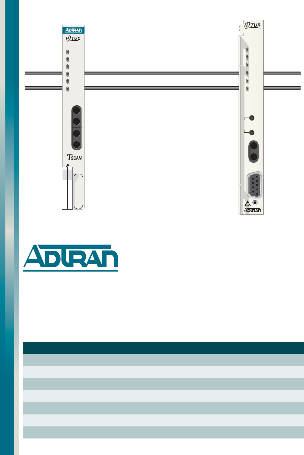
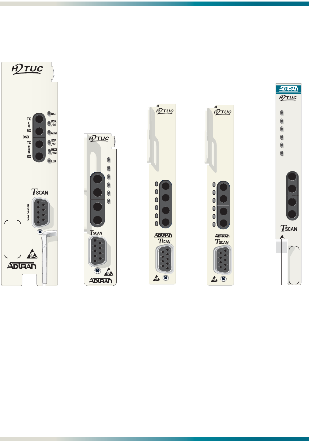
Figure 1 illustrates the front panels of the ADTRAN H2TU-C modules approved for general
distribution.
Figure 1. ADTRAN HDSL2 Central Office Units for General Distribution
220 H2TU-C
P/N 1223001L2
DDM+ H2TU-C
P/N 1223003L2
3192 H2TU-C
P/N 1223004L2
Total Access 3000
H2TU-C
P/N 1181113L2
1223001L2
1
1223003L2
R
S
2
3
2
TX
TX
RX
DSX MON
DSX EQ
ALM
DSL
LBK
ESF
/SF
DSX
/DS1
B8ZS
/AMI
RX
1223004L2
DSL TX
RX
TX
RX
DSX
/DS1
ALM
LBK
ESF
/SF
B8ZS
/AMI
DSX EQ
DSX MON
1181113L2
DSL
DSX/DS1
ALM
B8ZS/AMI
(YEL) (GRN)
ESF/ SF
(YEL) (GRN)
LBK
TX
RX
E
Q
M
O
N
TX
RX
1223004L12
DSL TX
RX
TX
RX
DSX
/DS1
ALM
LBK
ESF
/SF
B8ZS
/AMI
DSX EQ
DSX MON
3192M H2TU-C
P/N 1223004L12
HDSL2 for General Distribution Installation and Maintenance Practice Product Description
61223HDSL2L2-5B 3
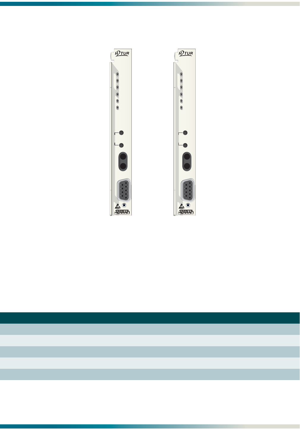
Figure 2 illustrates the front panels of the ADTRAN H2TU-R modules approved for general
distribution.
Figure 2. ADTRAN HDSL2 Remote Units for General Distribution
The H2TU-R is a T200 mechanics card which will fit Type 200 or Type 400 mechanics enclosures, as listed in
Table 3. This table also provides reference information on the ADTRAN enclosures.
Table 3. H2TU-R Enclosure Compatibility
Part Number Description1Document Number
1242007Lx HR12 Metal Enclosure Remote Shelf 61242007LX-5x
1242008L1 HR4 Remote Housing 61242008L1-5
1242034L2 T400 Single Mount (removable RJ-48 jacks) 61242034L2-5
1242034L3 T400 Single-Mount High Voltage Enclosure 61242034L3-5
1245034L12T200 Dual-Mount Installation/Maintenance 61245034L1-5
1. In all applications the H2TU-C must be installed in NEBS compliant and UL listed enclosures to insure full
compliance with this unit.
2 The T200 Dual-Mount housing (P/N 1245034L1) is required when using the T200 H2TU-C for HDSL Loop Support System
(HLSSTM) protection circuits.
T200 H2TU-R,
LOCAL POWERED
P/N 1223024L2
T200 H2TU-R,
SPAN POWERED
P/N 1223026L2
TX
RX
REM
LOC
L
B
K
1223024L2
DSL
LOCAL
DS1
ALM
(GRN)
SF
(YEL)
ESF/
(GRN)
AMI
(YEL)
B8ZS
/
(GRN)
RLB
(YEL)
LLB
/
C
U
S
R
S
2
3
2
T
M
O
N
TX
RX
REM
LOC
L
B
K
1223026L2
DSL
DS1
ALM
(GRN)
SF
(YEL)
ESF/
(GRN)
AMI
(YEL)
B8ZS
/
(GRN)
RLB
(YEL)
LLB
/
C
U
S
R
S
2
3
2
T
M
O
N

Product Description HDSL2 for General Distribution Installation and Maintenance Practice
461223HDSL2L2-5B
Compliance
ADTRAN HDSL2 modules are NRTL listed to the applicable UL standards. The HDSL2
modules are to be installed in a restricted access location and in a type “B” or “E” enclosure
only.
These devices comply with Part 15 of the FCC rules. Operation is subject to the following two
conditions:
1. This device may not cause harmful interference.
2. This device must accept any interference received, including interference that may cause
undesired operation.
Changes or modifications not expressly approved by ADTRAN could void the user’s authority
to operate this equipment.
H2TU-C Compliance
Table 4 shows the compliance codes for the H2TU-C modules.
The H2TU-C modules provide span powering voltage (negative only with respect to ground,
–190 VDC nominal, GFI protection <5 mA) and meets requirements of Bellcore
GR-1089-CORE (Class A2) and ANSI T1.418-2002.
H2TU-R Compliance
Table 5 shows the compliance codes for the H2TU-R modules.
The H2TU-R modules must only be installed in shelves or mountings that utilize pin 27 of the
edge connector as a frame ground.
Table 4. Compliance Codes, H2TU-C
Code Input Output
Power Code (PC) F C
Telecommunication Code (TC) – X
Installation Code (IC) A –
Table 5. Compliance Codes, H2TU-R
Code Input Output
Power Code (PC) C C
Telecommunication Code (TC) X X
Installation Code (IC) A –

HDSL2 for General Distribution Installation and Maintenance Practice Installation Guidelines
61223HDSL2L2-5B 5
INSTALLATION GUIDELINES
After unpacking an HDSL2 module, inspect it for damage. If damage has occurred, file a claim
with the carrier, then contact ADTRAN Customer Service. For more information, refer to
“Appendix D, Warranty”.
If possible, keep the original shipping container for returning the module for repair or for
verification of shipping damage.
CAUTION
Electronic modules can be damaged by Electro-Static Discharge
(ESD). When handling modules, wear an antistatic discharge wrist
strap to prevent damage to electronic components. Place modules
in antistatic packing material when transporting or storing. When
working on modules, always place them on an approved antistatic
mat that is electrically grounded.
ADTRAN HDSL2 modules plug directly into the enclosure. Installation wiring is not required.
WARNING
Up to –200 VDC may be present on telecommunications wiring.
The DSX-1 interface is intended for connection to intra-building
wiring only. Ensure chassis ground is properly connected.
NOTE
These products are intended for installation in restricted access
locations only.
C A U T I O N !
SUBJECT TO ELECTROSTATIC DAMAGE
OR DECREASE IN RELIABILITY.
HANDLING PRECAUTIONS REQUIRED.
Installation Guidelines HDSL2 for General Distribution Installation and Maintenance Practice
661223HDSL2L2-5B
Powering Options
H2TU-C
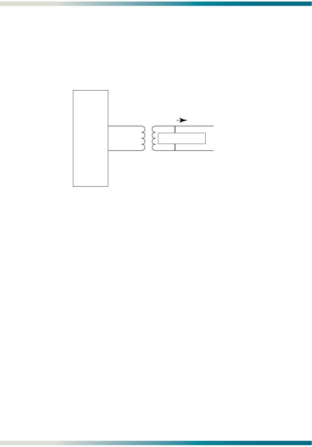
An H2TU-C module is capable of span powering an H2TU-R module by applying current to the
local loop. Current from 10 to 150 mA is coupled onto an HDSL2 span to power the H2TU-R
module when required. Figure 3 shows the HDSL2 span powering diagram.
Figure 3. HDSL2 Span Powering Diagram
H2TU-R Span Power
The H2TU-R P/N 1223026L2 receives span power from the H2TU-C.
H2TU-R Local Power
In some circumstances a locally powered remote unit is required. The H2TU-R
P/N 1223024L2 can meet those needs.
Module Installation
Follow the step-by-step procedures below to put the HDSL2 modules in service.
Total Access 3000 and 220/E220 H2TU-C Installation
To install the Total Access 3000 H2TU-C (P/N 1181113L2) or 220 H2TU-C module (P/N
1223001L2), perform the following steps:
1. Pull the ejector latch, located on the bottom of the module front panel, out from the closed
position.
2. Hold the unit by the front panel while supporting the bottom edge of the module with the
ejector latch opened to engage the enclosure edge.
3. Align the unit edges to fit in the lower and upper guide grooves for the module slot.
HDSL2
TIP (+)
RING (-)
SPAN POWER 190 V
SPAN CURRENT

HDSL2 for General Distribution Installation and Maintenance Practice Installation Guidelines
61223HDSL2L2-5B 7
4. Slide the unit into the module slot. Simultaneous thumb pressure at the top and bottom
of the unit will ensure that the module is firmly seated against the backplane of the
chassis.
5. Secure the module in place by pushing in on the ejector latch.
All Other Modules
To install any of the HDSL2 modules, with the exception of those explained above, perform the
following steps:
1. Hold the unit by the front panel while supporting the bottom edge of the module and
engage the enclosure edge.
2. Align the unit edges to fit in the lower and upper guide grooves for the enclosure slot.
3. Slide the unit into the access module slot. Simultaneous thumb pressure at the top and at
the bottom of the unit will ensure that the module is firmly seated against the backplane
of the enclosure.
NOTE
For the locally powered H2TU-R (P/N 1223024L2), a local power
supply (P/N 1353.DSK48V04) is available from ADTRAN.
Initialization
When a module is first installed, it performs a series of self-tests. Once the power up self-test
is complete, the status LEDs will reflect the true state of the hardware. For more information,
refer to “H2TU-C Front Panel Operation” on page 16 for LED indications.
Connections HDSL2 for General Distribution Installation and Maintenance Practice
861223HDSL2L2-5B
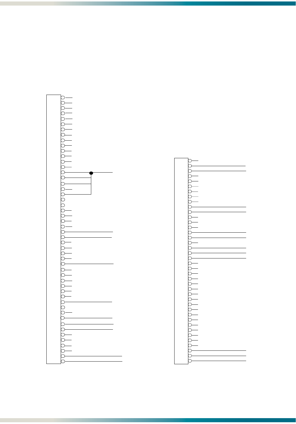
CONNECTIONS
An H2TU-C module occupies one card slot in the respective Office Repeater Bay for which it is
named. Power and alarm signals are provided to the module through the backplane of the
shelf. DSX-1 and HDSL2 loop signals are connected to the wire-wrap pins or mass termi-
nation (amphenol) shelf connectors corresponding to the slot the module occupies.
Figure 4, Figure 5, and Figure 6 specify the edge connection wiring required for proper
operation.
Figure 4. HDSL2 Edge Connector Wiring
1
2
3
4
5
6
7
8
9
10
11
12
13
14
15
16
17
18
19
20
21
22
23
24
25
26
27
28
29
30
31
32
33
34
35
36
37
38
39
40
41
42
43
44
45
46
47
48
49
50
-48 VDC RET
HDSL2 Tip (Wire-Wrap)
HDSL2 Ring (Wire-Wrap)
-48 VDC (1)
DSX-1 Rx In Tip (Wire-Wrap) Input to H2TU-C
DSX-1 Rx In Ring (Wire-Wrap) Input to H2TU-C
-48 VDC RET
DSX-1 Tx Out Tip (Wire-Wrap) Output from H2TU-C
DSX-1 Tx Out Ring (Wire-Wrap) Output from H2TU-C
Fuse Alarm
220 Edge
Connector Wiring
100
101
102
103
104
105
106
107
108
109
110
111
112
113
114
115
116
117
118
119
200
201
202
203
204
205
206
207
208
209
210
211
212
213
214
215
216
217
218
219
HDSL2 Tip
HDSL2 Ring
DSX-1 Rx Tip
DSX-1 Rx Ring
DSX-1 Tx Tip
DSX-1 Tx Ring
Fuse Alarm (to Alarm Module)
-48 VDC Return
Frame Ground
-48 VDC
-48 VDC Return
-48 VDC Return
DDM+ Edge
Connector Wiring

HDSL2 for General Distribution Installation and Maintenance Practice Connections
61223HDSL2L2-5B 9
Figure 5. HDSL2 Edge Connector Wiring, continued
3192 Edge
Connector Wiring
1
2
3
4
5
6
7
8
9
10
A
B
C
D
E
F
H
J
K
L
R1 Rx DSX (Out to DSX)
R Tx DSX (In from DSX)
GND
-48 VDC
R HDSL2 Loop
Fuse Alarm (to Alarm Module)
T Tx DSX (In from DSX)
T1 Rx DSX (Out to DSX)
Frame Ground
T HDSL2 Loop
T200 H2TU-R Edge
Connector Wiring
1
2
3
4
5
6
7
8
9
10
11
12
13
14
15
16
17
18
19
20
21
22
23
24
25
26
27
28
29
30
31
32
33
34
35
36
37
38
39
40
41
42
43
44
45
46
47
48
49
50
51
52
53
54
55
Chassis Ground
DS1 RX Out Tip
HDSL2 Loop Tip
Chassis Ground
DS1 RX Out Ring
-48 VDC Return
VCC (+5 VDC)
Chassis Ground
-48 VDC
PROT-1
DS1 TX In Ring
DS1 TX In Tip
3192M Edge
Connector Wiring
1
2
3
4
5
6
7
8
9
10
A
B
C
D
E
F
H
J
K
L
R1 Rx DSX (Out to DSX)
R Tx DSX (In from DSX)
GND
-48 VDC
R HDSL2 Loop
Fuse Alarm (to Alarm Module)
T Tx DSX (In from DSX)
T1 Rx DSX (Out to DSX)
Frame Ground
T HDSL2 Loop
HMU Management Bus
RCV LOS (To Alarm Module)

Provisioning HDSL2 for General Distribution Installation and Maintenance Practice
10 61223HDSL2L2-5B
Total Access 3000 H2TU-C Edge Connector
The Total Access 3000 shelf delivers DSX-1 from the network to the H2TU-C via connectors on
the backplane labeled Pair 7 and Pair 8. The HDSL2 signal is provided toward the customer via
the backplane connector labeled Pair 2. Pins 1 and 33 of the connectors Pair 7 and Pair 8 are
the DSX connections for the H2TU-C in slot 1. Pins 2 and 34 of these connectors are
associated with slot 2. Pins 3 and 35 are associated with slot 3, and so forth, up to pins 28
and 60 for slot 28.
Figure 6. HDSL2 Edge Connector Wiring, continued
PROVISIONING
HDSL2 Configuration is performed via software control. For more information, refer to
“Control Port Operation” on page 17. The provisioning settings can be viewed and manipu-
lated through access to the firmware via the front panel RS-232 port. Table 6 lists the
available provisioning options and their factory default settings.
1
2
3
4
5
6
7
8
9
10
11
12
13
14
15
16
17
18
19
20
21
22
23
24
25
26
27
28
29
30
31
32
1
2
3
4
5
6
7
8
9
10
11
12
13
14
15
16
17
18
19
20
21
22
23
24
25
26
27
28
29
30
31
32
1
2
3
4
5
6
7
8
9
10
11
12
13
14
15
16
17
18
19
20
21
22
23
24
25
26
27
28
29
30
31
32
P2, Row A P2, Row B P2, Row C
- 48 volt return
Interrupt Request
MUX B Receive Data
MUX A Receive Clock
MUX A Receive Data
Chassis ground
Chassis ground
SCU Control Lead
Fuse alarm
Interrupt Request Select
MUX B Transmit Clock
MUX A Transmit Clock
Test access bus Loop ring
Test access bus Loop tip
Receive DSX-1 Ring backup connection
Transmit DSX-1 Ring backup connection
Receive DSX-1 Ring normal connection
Transmit DSX-1 Ring normal connection
- 48 volt return
- 48 volt DC A
- 48 volt DC A
HDSL2 Loop Ring (facility)
HDSL2 Loop Tip (facility)
SCU Control Lead
SCU Control Lead
SCU Serial Interface
MUX B Transmit Data
MUX B Receive Clock
MUX A Transmit Data
Receive DSX-1 Tip backup connection
Transmit DSX-1 Tip backup connection
Receive DSX-1 Tip normal connection
Transmit DSX-1 Tip normal connection
- 48 volt DC B
- 48 volt DC B
Total Access 3000
H2TU-C Edge Connector Wiring

HDSL2 for General Distribution Installation and Maintenance Practice Provisioning
61223HDSL2L2-5B 11
Table 6. Provisioning Options
Provisioning Option Option Settings Default Settings
1. DSX-1 Line Build Out 1 0-133 feet, 133-266 feet,
266-399 feet, 399-533 feet,
533-655 feet, EXTERNAL
0 to 133 feet
2. DSX-1/DS1 Line Code B8ZS, AMI B8ZS
3. DSX-1/DS1 Framing SF, ESF, Unframed, Auto ESF
4. Force Frame Conversion Disabled, Enabled Disabled
5. Smartjack Loopback Disabled, Enabled Enabled
6. Loopback Time Out None, 120 Min 120 Minutes
7. Latching Loopback Mode2T1 (Disabled), FT1 (Enabled) T1 (Disabled)
8. DS1 Tx Level 0 dB, –7.5 dB, –15 dB 0 dB
9. Span Power Enabled, Disabled Enabled
10. Customer Loss Indicator3AIS, Loopback, AIS/CI AIS/CI
11. Performance Reporting Messages None, SPRM, NPRM, AUTO (both) AUTO
12. Loop Attenuation Alarm Threshold 0 (Disabled), 1-99 dB 30 dB
13. SNR Margin Alarm Threshold 0 (Disabled), 1-15 dB 04 dB
14. Remote Provisioning Disabled, Enabled Enabled
15. Shelf Alarm 4Disabled, Enabled Enabled
2. External is used only for Kentrox shelves. Unit transmits 12-volt p-p to DSX panel.
3. Latching Loopback Mode
• T1 - When optioned for T1 mode, the unit does not respond to DDS Latching Loopback codes.
• FT1 (Fractional T1) - DDS Latching Loopback operation is supported. The H2TU-C units which are in the
HDSL circuit are treated as Identical Tandem Data ports and the HTU-R is treated as a different Tandem
Data port.
Note: When operating in FT1 mode and during periods of T1 loss of signal, LOS, or T1 AIS from the customer
CI, the HDSL system will send in the network direction from the HTU-C a Fractional DS1 idle signal
consisting of a repeating 7E (HEX) byte payload within a framed/unframed T1 signal. In addition,
when optioned for FT1 mode, the setting for Customer Loss Response is ignored.
4. Customer Loss Indicator
• AIS - Send AIS to network upon T1 loss of signal or T1 AIS from customer.
• LPBK - HTU-R initiates a network loopback upon T1 loss of signal or T1 AIS from customer.
• AIS/CI - HTU-R sends customer disconnect indication upon loss of signal, loss of synchronization, or receipt
of T1 AIS from customer.
Note: The CI is generated by transmitting the framing received from the network while overwriting the
payload with a repeating pattern. For applications where the DS1 is Extended Superframe, the data
link is overwritten with a Yellow Alarm that is interrupted once every second by a 100 milli-second
code burst of 7E (HEX).
5. Shelf Alarm is on the DDM+, 3192M, and 3192 Units only.

HDSL2 System Testing HDSL2 for General Distribution Installation and Maintenance Practice
12 61223HDSL2L2-5B
Provisioning Options, Total Access 3000 H2TU-C
The Total Access 3000 H2TU-C is provisioned through the SCU on the Total Access 3000
chassis. In addition to the options shown in Table 6 on page 11, the options shown in Table 7
apply.
HDSL2 SYSTEM TESTING
The ADTRAN HDSL2 system provides the ability to monitor the status and performance of the
DSX-1 signals, DS1 signals, and HDSL2 loop signals. Detailed performance monitoring is
provided by the front panel-mounted RS-232 control port (or via the SCU RS-232 port for the
Total Access 3000). These features are valuable in troubleshooting and isolating any system
level problems that may occur at installation or during operation of the HDSL2 system.
Additional testing features are described below.
Table 7. Total Access 3000 Additional Provisioning Options
Provisioning Option Option Settings Default Settings
15. Service State1In Service;
Out-of-Service Unassigned;
Out-of-Service Maintenance
Out-of-Service
Maintenance
16. Network Source2DSX, MUX A, MUX B, Auto MUX DSX
17. External Alarms Enabled, Disabled Disabled
18. Auto In Service Disabled, Enabled Enabled
19. Auto IS Startup Period 1 hour, 4 hours, 8 hours,
24 hours
4 hours
20. Auto IS Off Period 1 hour, 4 hours, 8 hours,
24 hours
8 hours
1. The Service State defaults to Out-of-Service Maintenance. This setting allows active connections to the DSX or
MUX interface; however, no alarms will be generated. Out-of-Service Unassigned allows the loops to train up
but will not connect to the DSX or MUX interface. The In Service setting allows full functioning connections to
DSX or MUX interfaces.
2. For Network Source settings, the following options apply:
• DSX-1: The module will utilize the DSX-1 interface. The Muxes will not be used, even if present.
• Mux A: The module will use Mux A as its data source. The module will not switch to Mux B in the case of a
Mux A failure. The EQ jacks can be used as a temporary test point in conjunction with the EQ jack setting
on the loopback/test screen.
• Mux B: The module will use Mux B as its data source. The module will not switch to Mux A in the case of a
Mux B failure. The EQ jacks can be used as a temporary test point in conjunction with the EQ jack setting
on the loopback/test screen.
• Auto Mux: The module will default to Mux A as its data source. In the event of a Mux A failure, the module
will perform a protection switch to Mux B if it is present and in service. The EQ jacks can be used as a
temporary test point in conjunction with the EQ jack setting on the loopback/test screen.

HDSL2 for General Distribution Installation and Maintenance Practice HDSL2 System Testing
61223HDSL2L2-5B 13
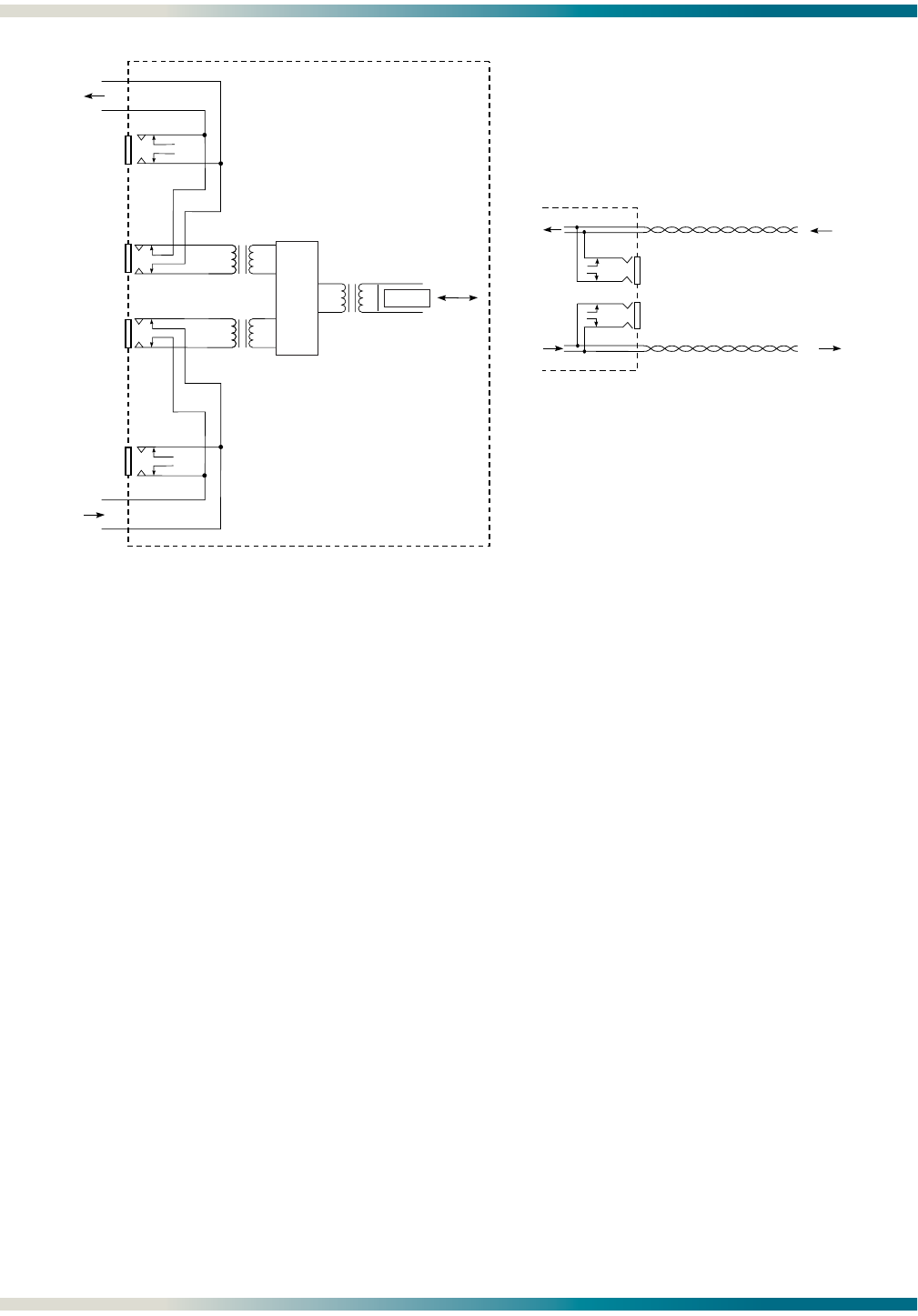
H2TU-C Bantam Jacks
The front panel of an H2TU-C module contains both metallic splitting (EQ) and monitor (MON)
bantam jacks.
The EQ jacks provide an intrusive access point, interrupting signal access to the local loop.
This will enable the user to transmit a test signal toward an H2TU-R module and to receive a
test signal from an H2TU-R module.
The MON jacks, when connected to a bit-error rate test set that is configured for monitor
(bridging) mode, provide a nonintrusive test access point for observing the transmit or receive
signal. In this configuration, synchronization, test patterns, and other functions can be
observed.
Alternatively, the MON jacks can also be used for intrusive testing toward the network. To
utilize this configuration, perform the following steps:
1. Disconnect the H2TU-C DSX-1 interface by opening both the metallic splitting TX and RX
EQ jacks with either a bantam open plug or a bantam test cord that is not terminated.
2. Configure a test set for Terminate mode.
3. Connect the test set to the MON jacks. (Test access toward the network equipment is
achieved).
4. Connect the output (TRANS) of the test set to the MON RX jack, and the input (REC) of the
test set to the MON TX jack.
NOTE
For additional Bantam Jack testing from the Total Access 3000
H2TU-C (P/N 1181113L2), refer to “Appendix C, Front Panel DSX
and MUX Mode Test Access”.
H2TU-R Bantam Jacks
The DS1 monitoring from the H2TU-R is accomplished using the MON bantam jacks.
The jacks labeled MON provide a test access point for monitoring the transmit and receive
signals at the DS1 interface point. The bridging jacks can be used in two different ways:
1. The bridging jack of an H2TU-R module provides a nonintrusive tap onto a signal line and
permits the connection of test equipment to monitor the characteristics of the signal with
the DS1 test set optioned for Bridging mode.
2. If the DS1 test set is optioned for Terminate mode and the customer DS1 is disconnected,
then the bridging jack of an H2TU-R module provides an intrusive tap and could be used
to transmit and receive signals between an H2TU-R module and the network.
Figure 7 illustrates the complete bantam jack arrangement and details for specific jacks.
HDSL2 System Testing HDSL2 for General Distribution Installation and Maintenance Practice
14 61223HDSL2L2-5B
Figure 7. Bantam Jack Arrangements
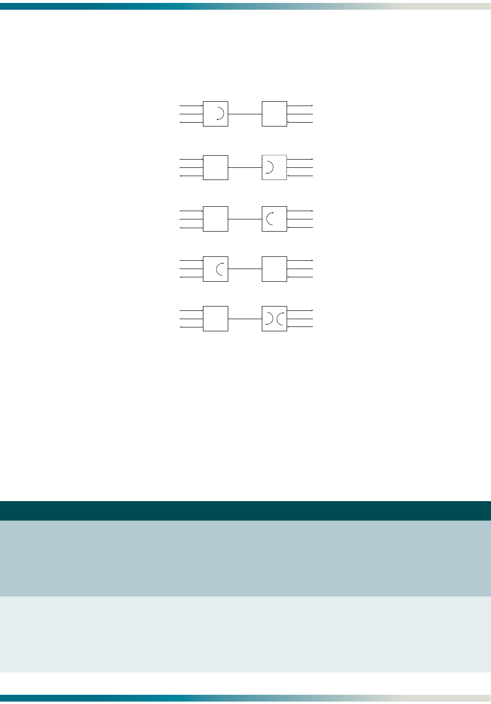
Loopbacks
The ADTRAN HDSL2 modules respond to three different loopback activation processes. These
processes may be utilized to provide a loopback that affects either an H2TU-C or an H2TU-R
module (locally or remotely).
1. Loopbacks may be activated using the craft interface. The Loopback Options screen that
provides for the H2TU-C and H2TU-R loopbacks is described in “Control Port Operation”
on page 17.
2. The modules respond to the industry standard for HDSL loopbacks. A detailed description
of these loopback sequences is given in “Appendix A, HDSL2 Loopbacks”.
3. HDSL2 modules respond to loopbacks depending on the module type as follows:
• H2TU-C modules respond to loopbacks initiated using the software functions described
in 1 and 2 above.
• H2TU-R modules respond to loopbacks initiated using front panel pushbuttons. See
Table 8.
ADTRAN HDSL2 modules contain smartloop technology which constantly monitors the DSX-1
for a framing pattern. ADTRAN HDSL2 modules will initiate the proper loopback regardless of
how the loopback control sequence is sent (framed or unframed).
The loopback condition imposed in both cases is a logic level loopback at the point within an
H2TU-C module where the DSX-1 signal passes into the HDSL2 modulators. Figure 8 depicts
all of the loopback locations possible with ADTRAN HDSL2 equipment.
DSX-1
BRG
Rx
H2TU-C
DATA
PUMP
DSX-1
T1
R1
DSX-1
T
R
HDSL2
EQ
Rx
DSX-1
BRG
Tx
EQ
Tx
POWER
Tx
Rx
DS1
MON
CPE
DS1
INTERFACE
H2TUR
T
R
T1
R1
H2TU-C Bantam Jack Arrangement
(except DDM+ H2TU-C)
H2TU-R Bantam Jack Arrangement
HDSL2 for General Distribution Installation and Maintenance Practice HDSL2 System Testing
61223HDSL2L2-5B 15
In addition to network-side loopbacks, an H2TU-C module provides customer-side loopbacks
initiated by using either the terminal control port or in-band loop codes. For more infor-
mation, refer to “Appendix A, HDSL2 Loopbacks”. In this mode, an AIS signal (all ones) is
supplied to the network.
Figure 8. HDSL2 Loopbacks
H2TU-R Front Panel Pushbuttons
Two loopback (LBK) pushbuttons are accessible from the front panel of the H2TU-R. The REM
loopback button controls a customer loopback at the H2TU-C. The LOC loopback button
controls a bidirectional loopback at the H2TU-R. Table 8 details the loopback pushbutton
operation.
Table 8. Front Panel Loopback Pushbuttons
Switch Label Function
REM Pressing this button changes the H2TU-C loopback state as follows:
• If the H2TU-C is not in loopback, pressing this button will activate a bilateral
loopback.
• If the H2TU-C is in loopback, pressing this button will deactivate the bilateral
loopback.
LOC Pressing this button changes the H2TU-R loopback state as follows:
• If the H2TU-R is not in loopback, pressing this button will activate a bilateral
loopback.
• If the H2TU-R is in loopback, pressing this button will deactivate the bilateral
loopback.
DSX-1
H2TU-C
LOCAL
LOOP
H2TU-C Network-Side Loopback
H2TU-R
H2TU-C
LOCAL
LOOP
H2TU-R Customer-Side Loopback
H2TU-R
H2TU-C
LOCAL
LOOP
H2TU-C Customer-Side Loopback
H2TU-R
X
X
DS1
DSX-1
DSX-1
DSX-1
LOCAL
LOOP
H2TU-R Network-Side Loopback or
H2TU-R NIU Loopback
DS1
DS1
DS1
X
AIS
AIS
AIS
AIS
X = Signal Inactive
H2TU-C
LOCAL
LOOP
H2TU-R Bilateral Loopback
DS1DSX-1
H2TU-R
H2TU-C H2TU-R
X
H2TU-C Front Panel Operation HDSL2 for General Distribution Installation and Maintenance Practice
16 61223HDSL2L2-5B
H2TU-C FRONT PANEL OPERATION
LED indicators mounted on the front panel of the unit provide status of the HDSL2 circuit.
Each indicator is described in Table 9 for the H2TU-C and Table 10 for the H2TU-R.
Table 9. H2TU-C Front Panel LED Indications
Front
Panel Label Status Description
DSL Green
Red
DSL sync, no errors currently detected, and signal margin ≥ 2 dB
No DSL sync, errors being detected, or signal quality < 2 dB
DSX/DS1 Green
Red
DSX-1 signal is present and synchronized and no errors are
detected
No DSX-1 signal, or signal is present with errors
ALM Off
Red
Yellow
No alarm condition detected
Loss of DSX-1 signal to the unit
Loss of DS1 signal to the remote
ESF/SF Off
Green
Yellow
Unit is provisioned for unframed data
Unit is provisioned for SF data
Unit is provisioned for ESF data
B8ZS/AMI Green
Yellow
Unit is provisioned for AMI line code
Unit is provisioned for B8ZS line code
LBK Off
Yellow
Unit is not in loopback
Unit loopback is active toward network or customer
Table 10. H2TU-R Front Panel LED Indications
Front
Panel Label Status Description
DSL Green
Red
DSL sync, no errors currently detected, and signal margin > 2 dB
No DSL sync, errors being detected, or signal margin ≤ 2 dB
DS1 Green
Red
DS1 signal is present and no errors currently being detected
No DS1 signal or framing mismatch
ALM Off
Red
Yellow
No active alarm present
Loss of DS1 signal to the unit
Loss of DSX signal to the H2TU-C
ESF/SF Off
Green
Yellow
Unit is provisioned for UNFRAMED data
Unit is provisioned for SF data
Unit is provisioned for ESF data
B8ZS/AMI Green
Yellow
Unit is provisioned for AMI line code
Unit is provisioned for B8ZS line code
LLB/RLB Off
Green
Yellow
Unit is NOT in loopback
Active remote loopback from the H2TU-C toward the customer
This unit is in loopback (network and/or customer)
1181113L2
DSL
DSX/DS1
ALM
B8ZS/AMI
(YEL) (GRN)
ESF/ SF
(YEL) (GRN)
LBK
TX
RX
E
Q
LOC
L
B
K
1223024L2
DSL
LOCAL
DS1
ALM
(GRN)
SF
(YEL)
ESF/
(GRN)
AMI
(YEL)
B8ZS
/
(GRN)
RLB
(YEL)
LLB
/
URH T

HDSL2 for General Distribution Installation and Maintenance Practice Control Port Operation
61223HDSL2L2-5B 17
CONTROL PORT OPERATION
The H2TU-C modules provide a DB-9 connector on the front panel that supplies an RS-232
interface for connection to a controlling terminal. The pinout of the DB-9 is illustrated in
Figure 9.
Figure 9. RS-232 (DB-9) Pin Assignments
The Total Access 3000 H2TU-C Control Port access is provided via the DB-9 connector on the
Total Access System Controller Unit (SCU), P/N 1181018L1. This section will include Total
Access H2TU-C screens separately where they differ from other HDSL2 screens.
The terminal interface operates at data rates from 1.2 kbps to 19.2 kbps. (Total Access 3000
SCU default rate is 9.6 kbps.)
The asynchronous data format is fixed at the following parameters:
8 data bits; no parity; 1 stop bit
Disable the line wrap feature of the emulation program if necessary.
NOTE
If using a personal computer (PC) with terminal emulation capabil-
ity, be sure to disable any power saving programs. Otherwise, com-
munication between the PC and the HDSL2 unit may be disrupted,
resulting in misplaced characters or screen time outs.
Terminal Emulation Modes
An H2TU-C module supports two types of terminal emulation modes:
• Manual Update Mode - This mode is a dumb terminal mode, enabling easy access to print
screen and log files commands. This mode also includes a “3 SPACES TO UPDATE”
message on the top of the terminal screen (press the spacebar three times to update the
screen).
• Real Time Update Mode (default) - This mode is a VT100 terminal mode. This mode enables
all screen highlighting and cursor placement. Print screen and log file commands are not
available in this mode.
NOTE
The Manual Update Mode is not available on the Total Access 3000
H2TU-C.
6
7
8
9
1
2
3
4
5
TXD (Transmit Data)
RXD (Receive Data)
SGN (Signal Ground)

Control Port Operation HDSL2 for General Distribution Installation and Maintenance Practice
18 61223HDSL2L2-5B
Screens
The screens illustrated in Figure 10 through Figure 47 are for an HDSL2 circuit deployed with
the ADTRAN HDSL2 technology. The circuit includes an H2TU-C module and an H2TU-R
module.
Logon to Main Menu
A terminal session is initiated by entering multiple spacebar characters, which are used by an
H2TU-C module to determine the speed of the terminal. Once the speed has been determined,
the ADTRAN HDSL2 Main Menu is displayed from which the various Operation, Adminis-
trative, Maintenance, and Provisioning (OAM&P) screens may be accessed (Figure 10). To
display a particular screen from the menu, press the number key associated with the screen
title, and press the ENTER key.
NOTE
When the ADC HiGain® Management Unit (HMU) is installed, the
3192M DB-9 is disabled. Terminal screens must be accessed from
any one of these HMUs:
HMU-319-L7A
HMU-319-L7AV307
HMU-319-L7A32.
Figure 10. ADTRAN HDSL2 Main Menu
Circuit ID:HNTSVLALHDSL2 03/01/05 09:29:45
Adtran HDSL2 Main Menu
1. HDSL2 Unit Information
2. Provisioning
3. Span Status
4. Loopbacks and Test
5. Performance History
6. Scratch Pad, Ckt ID, Time/Date
7. Terminal Modes
8. Alarm History
9. Event History
10. System PM/Screen Report
11. Clear PM and Alarm Histories
12. Troubleshooting
13. Virtual Terminal Control
Selection:

HDSL2 for General Distribution Installation and Maintenance Practice Control Port Operation
61223HDSL2L2-5B 19
Descriptions for the menu items on the HDSL2 Main Menu include the following:
•“HDSL2 Unit Information” on page 21
•“Provisioning” on page 22
•“Span Status” on page 24
•“Loopbacks and Test” on page 27
•“Performance History” on page 31
•“Scratch Pad, Circuit ID, Time/Date Screen” on page 33
•“Terminal Modes” on page 34
•“Alarm History” on page 35
•“Event History” on page 38
•“System PM/Screen Report” on page 39
•“Clear PM and Alarm Histories” on page 39
•“Troubleshooting” on page 40
•“Virtual Terminal Control” on page 46
Logon to Main Menu, Total Access 3000 H2TU-C
Accessing the HDSL2 circuit information via the Total Access 3000 SCU control port requires
the user to logon by entering a user name and password (Figure 11). The default account
name is ADMIN. The default password is PASSWORD.
After successful logon, the Total Access Main Menu (Figure 12) will appear. Select Access
Modules (option 4) from this menu.
Figure 11. Logon Screen
TID: Total Access System 03/01/05 09:29
Unit Number: 1
Total Access System
Account Name :
'?' - System Help Screen

Control Port Operation HDSL2 for General Distribution Installation and Maintenance Practice
20 61223HDSL2L2-5B
Figure 12. Total Access Main Menu
The Access Module Menus screen (Figure 13) will display the access modules occupying the
Total Access 3000 shelf. Select the corresponding channel slot number for the desired
H2TU-C. To the right of each access module listed, the current alarm state is indicated.
When the module is selected, the ADTRAN HDSL2 Main Menu is displayed, from which the
various Operation, Administrative, Maintenance, and Provisioning (OAM&P) screens are
accessed (Figure 14). To display a particular screen from the menu, press the number key
associated with the screen title, and then press the ENTER key.
Figure 13. Access Module Menus Screen
Shelf: 1 Total Access System 03/01/05 09:29
Unacknowledged Alarms: None
Total Access
1. System Controller
2. Common A - [.....]
3. Common B - [.....]
4. Access Modules
5. System Alarms
6. Network Management
7. Logoff
Selection:
'?' - System Help Screen
Shelf: 1 Total Access System 03/01/05 09:29
Unacknowledged Alarms: None
Access Module Menus
1 - H2TU-C L2... [None] 15 - ............ [None]
2 - ............ [None] 16 - ............ [None]
3 - ............ [None] 17 - ............ [None]
4 - ............ [None] 18 - ............ [None]
5 - ............ [None] 19 - ............ [None]
6 - ............ [None] 20 - ............ [None]
7 - ............ [None] 21 - ............ [None]
8 - ............ [None] 22 - ............ [None]
9 - ............ [None] 23 - ............ [None]
10 - ............ [None] 24 - ............ [None]
11 - ............ [None] 25 - ............ [None]
12 - ............ [None] 26 - ............ [None]
13 - ............ [None] 27 - ............ [None]
14 - ............ [None] 28 - ............ [None]
Enter Channel Slot Number :

HDSL2 for General Distribution Installation and Maintenance Practice Control Port Operation
61223HDSL2L2-5B 21
Figure 14. Total Access 3000 H2TU-C Main Menu Screen
HDSL2 Unit Information
The Unit Information screen (Figure 15) provides detailed product information on each
component in the HDSL2 circuit. ADTRAN Technical Support contact numbers are also
available from the Unit Information screen. This screen is shown as an example of an actual
HDSL2 screen.
Figure 15. ADTRAN Information Screen
Shelf: 1 Slot: 15 Total Access System 03/01/05 09:29
Unacknowledged Alarms: None
Circuit ID:
HDSL2 Main Menu
1. HDSL2 Unit Information
2. Provisioning
3. Status
4. Loopbacks and Test
5. Performance Monitoring
6. Scratch Pad, Ckt ID
7. Alarm History
8. Event History
9. System Status/PM Report
10. Clear PM and Alarm Histories
11. Troubleshooting
12. Flash Upgrade
Selection:
Circuit ID:HNTSVLALHDSL2 03/01/05 09:29:45
Press ESC to return to previous menu
ADTRAN
901 Explorer Boulevard
Huntsville, Alabama 35806-2807
--------------------- For Information or Technical Support --------------------
Support Hours ( Normal 7am - 7pm CST, Emergency 7 days x 24 hours )
Phone: 800.726.8663 / 888.873.HDSL Fax: 256.963.6217 Internet: www.adtran.com
-------------------------------------------------------------------------------
ADTN H2TU-C ADTN H2TU-R
P/N: 1223001L2 P/N: 1223026L2
S/N: FD14E3648 S/N: 123456789
CLEI: T1L7J2MAAA CLEI: T1L8MOKCAA
Manf: 08/08/2004 Manf: 08/01/2004
Ver: A07 Ver: A09

Control Port Operation HDSL2 for General Distribution Installation and Maintenance Practice
22 61223HDSL2L2-5B
Provisioning
The Provisioning menu (Figure 16) displays current settings. To change a particular option
setting (for example, “1” for DSX-1 Line Build Out) select the appropriate number, press ENTER,
and the new menu will appear with a list of the available settings. To return to this screen
and/or the Main Menu, press ESC. To re-deploy this unit, press D which will restore the factory
default settings to those shown in Table 6 on page 11.
Figure 16. Provisioning Screen
NOTE
DSX-1 Line Build Out is set to 0-133 feet. This option is set to
EXTERNAL if using a Kentrox shelf. Otherwise, the LBO option
should be set to zero (0).
NOTE
Shelf Alarm option is on the DDM+ and 3192 modules only.
Total Access 3000 H2TU-C Provisioning Menu
Two screens comprise the provisioning menu for the Total Access 3000 H2TU-C. Figure 17
illustrates the first page of the menu.
Press the N (and ENTER) to move forward to the next screen. Figure 18 shows the remainder of
the Provisioning menu.
To return to the previous screen, press P.
To return to the Main Menu, press ESC.
Circuit ID:HNTSVLALHDSL2 03/01/05 09:29:45
Press ESC to return to previous menu
Provisioning
1. DSX-1 Line Buildout = 0-133 feet
2. DSX-1/DS1 Line Code = B8ZS
3. DSX-1/DS1 Framing = ESF
4. Forced Frame Conversion = Disabled
5. Smartjack Loopback = Enabled
6. Loopback Timeout = 120 Minutes
7. Latching Loopback Mode = T1 (Disabled)
8. DS1 TX Level = 0 dB
9. Span Power = Enabled
10. Customer Loss Indicator = AIS / CI
11. PRM Setting = AUTO
12. Loop Atten Alarm Thres = 30 dB
13. SNR Margin Alarm Thres = 04 dB
14. Remote Provisioning = Enabled
15. Shelf Alarm = Enabled
D. Restore Factory Defaults
Selection:

HDSL2 for General Distribution Installation and Maintenance Practice Control Port Operation
61223HDSL2L2-5B 23
To re-deploy this unit, press D which restores the factory default settings to those shown in
Table 6 and Table 7. The options shown in these tables are available with the H2TU-R (P/N
1223026L2). Some settings may differ when using different H2TU-Rs.
Figure 17. Provisioning Menu, Page 1
Figure 18. Provisioning Menu, Page 2
Shelf: 1 Slot: 14 Total Access System 03/01/05 09:29
Unacknowledged Alarms: None
Circuit ID:
Provisioning
1. DSX-1 Line Buildout = 0-133 Feet
2. DSX-1/DS1 Line Code = B8ZS
3. DSX-1/DS1 Framing = ESF
4. Forced Frame Conversion = Disabled
5. Smartjack Loopback = Enabled
6. Loopback Timeout = 120 Min
7. Latching Loopback Mode = T1 (Disabled)
8. DS1 TX Level = 0 dB
9. Span Power = Enabled
10. Customer Loss Indicator = AIS / CI
11. PRM Setting = AUTO
12. Loop Atten Alarm Thres = 30dB
13. SNR Margin Alarm Thres = 04dB
14. Remote Provisioning = Enabled
15. Service State = OOS Maintenance
16. Network Source = DSX
N. Next Page
Selection:
Shelf: 1 Slot: 14 Total Access System 03/01/05 09:29
Unacknowledged Alarms: None
Circuit ID:HntsvlALMn0103
Provisioning
17. External Alarms = Disabled
18. Auto In Service = Enabled
19. Auto IS Startup Period = 4 hours
20. Auto IS Off Period = 8 hours
D. Restore Factory Defaults
P. Previous Page
Selection:

Control Port Operation HDSL2 for General Distribution Installation and Maintenance Practice
24 61223HDSL2L2-5B
Span Status
The Span Status Screen (Figure 19) provides quick access to status information for each
HDSL2 receiver in the circuit.
Figure 19. Span Status Screen
The Total Access 3000 Span Status Screen (Figure 20) includes an option to access the Auto
In Service feature of Total Access 3000.
Figure 20. Span Status Screen, Total Access 3000
Circuit ID:HNTSVLALHDSL2 03/01/05 09:29:45
Press ESC to return to previous menu
Span Status Screen
ATTEN
______ <-00dB-> ______
|H2TUC | |H2TUR |
--LOS->| | | |------>
| | | |
NET | |<--------->| | CUST
| |17dB 17dB| |
<------| | MARGIN | |<-LOS--
DSX-1 |______| |______| DS1
1. Legend
2. Detailed Status
Selection:
Shelf: 5 Slot: 22 Total Access System 03/01/05 09:29
Unacknowledged Alarms: None
Circuit ID:
Span Status Screen
ATTEN
______ <-02dB-> ______
|H2TU-C | |H2TU-R |
------>| | | |------>
| | | |
NET | |<--------->| | CUST
| |17dB 17dB| |
<------| | MARGIN | |<------
DSX-1 |______| |______| DS1
1. Legend
2. Detailed Status
3. View Auto In Service Status
Selection:

HDSL2 for General Distribution Installation and Maintenance Practice Control Port Operation
61223HDSL2L2-5B 25
Status Screen Legend Screen
The Status Screen Legend (Figure 21) provides a description of messages used on the Status
screens.
Figure 21. Status Screen Legend
Detailed Status Screen
The Detailed Status selection from the Span Status Screen menu (Figure 22) displays the T1
and HDSL2 status for each receiver point.
Figure 22. Detailed Status Screen
Press ESC to return to previous menu
STATUS SCREEN LEGEND
Loop Attenuation
______ <---------- 25dB ------------> ______
|H2TUC | |H2TUR |
<------| | | |------>
| | | |
| | | |
| |<---------------------------------->| |
| |9dB 8dB| |
| | | | | |
------>| | Signal Margin | | |<------
|______| above 10e-7 BER | |______|
for H2TUC Receiver |
Signal Margin
above 10e-7 BER
Alarm Indicators: Error Indicators: for H2TUR Receiver
LOS = Loss of Signal ES = Errored Second
LOF = Loss of Frame Sync SES = Severely Errored Second
RAI = Yellow Alarm UAS = Unavailable Second
AIS = Blue Alarm
Circuit ID:HNTSVLALHDSL2 03/01/05 09:29:45
Press ESC to return to previous menu
Detailed HDSL2 and T1 Status
HDSL2 RECEIVER DATA
H2TU-C H2TU-R
-------- --------
MARGIN(CUR/MIN/MAX): 17/17/17 17/17/17
ATTEN(CUR/MAX): 00/00 00/00
ES 15MIN: 000 000
SES 15MIN: 000 000
UAS 15MIN: 000 000
T1 RECEIVER DATA
DSX-1 DS1
------- -------
FRAMING: UNFR UNFR
LINE CODE: B8ZS B8ZS
ES-P/ES-L: 000/000 000/000 1. Zero Registers
SES-P/SES-L: 000/000 000/000 2. Restart Min/Max
UAS-P/UAS-L: 000/000 000/000
ALARMS: None None Selection:

Control Port Operation HDSL2 for General Distribution Installation and Maintenance Practice
26 61223HDSL2L2-5B
Total Access 3000 H2TU-C Auto In Service Status Screen
The Auto In Service Status Screen (Figure 23) provides the status of the Auto In Service
feature.
The T1 alarm indications will display if the External Alarms option is enabled on the Provi-
sioning menu (Figure 17).
The Auto In Service Status screen also indicates the startup or exit period remaining as either
1, 4, 8, or 24 hours. This is the time during which the unit monitors both loop synchroni-
zation (Loop Sync) and T1 alarms (if enabled) and will only go into (or out of) service if the
circuit remains synchronized and without T1 alarms during the entire measured period.
These times are also set from the Provisioning menu. System responses displayed in the
status fields on this screen are shown in Table 11 below.
A single menu option is provided to view the Alarm History Screen. This screen is also
available by selecting the HDSL2 Main Menu option.
Figure 23. Auto In Service Screen
Table 11. Auto In Service Status Indications
Status Field Name System Indications
Current Auto In Service State (line 1) In-Service
Out-of-Service Maintenance
Auto In Service Status (line 2) Currently in startup period
Currently in exiting period
OK, Startup Period COMPLETED
OK, Startup INCOMPLETE (forced in-service)
Auto In Service Criteria (line 3) DSL Loop Sync (T1 alarms ignored)
DSL Loop Sync and absence of T1 alarms
Criteria (current status) DSL Loop Sync = OK or LOS (LOS shown in Figure 23)
T1 Alarm Status = Alarm or OK
Shelf: 1 Slot: 15 Total Access System 03/01/05 09:29
Unacknowledged Alarms: None
Circuit ID:
Auto In Service Status Screen
Current Auto In Service State = Out-of-Service Maintenance
Auto In Service Status = Currently in Startup Period
Auto In Service Criteria = DSL Loop Sync (T1 alarms ignored)
NOTE: The external alarms provisioning option determines
whether T1 alarms are an auto in service criterion.
Enabling external alarms sets T1 alarms as a criterion.
Criteria Status
--------------- ------
DSL Loop Sync LOS
---Startup Period Timer---
4 hrs 0 mins
--------------------------------------------------------------------------------
1. View Alarm History
Selection:

HDSL2 for General Distribution Installation and Maintenance Practice Control Port Operation
61223HDSL2L2-5B 27
Loopbacks and Test
The Loopback and Test Commands screen (Figure 24) provides the user with the ability to
initiate or terminate all available HDSL2 loopbacks. Each HDSL2 circuit component can be
looped toward the network or customer from this screen. Unit self tests can also be initiated
from this screen. A “Loop Down ALL Units” command will be available in lieu of the “Run Self
Tests” option when any loopback is active.
Figure 24. Loopback and Test Commands Screen
Total Access 3000 H2TU-C Loopback and Test Screen
The Total Access 3000 H2TU-C (Figure 25) has the following additional features:
• Equipment Jack - Select Network or Customer for testing purposes. Refer to “Appendix C,
Front Panel DSX and MUX Mode Test Access” for details.
• BERT Test Functions
Circuit ID:HNTSVLALHDSL2 03/01/05 09:29:45
Press ESC to return to previous menu
Loopback and Test Commands
______ ______
|H2TUC | |H2TUR |
------>| | | |------>
| | | |
NET | |<--------->| | CUST
| | | |
<------| | | |<------
DSX-1 |______| |______| DS1
1. Run Self Tests
2. H2TU-C Loopup Network
3. H2TU-C Loopup Customer
4. H2TU-R Loopup Network
5. H2TU-R Loopup Customer
Selection:

Control Port Operation HDSL2 for General Distribution Installation and Maintenance Practice
28 61223HDSL2L2-5B
Figure 25. Total Access 3000 H2TU-C Loopback and Test Commands Screen
BERT Test Functions
The Bit Error Rate Testing (BERT) Test Screen (Figure 26) is accessed by selecting the
associated number on the Loopback and Test menu. A five-selection menu is at the bottom of the
screen. Option 1, (Re)start Pattern is used to start (or restart) a test, and option 2, Stop Test is
used to manually stop the test.
NOTE
The BERT only runs unframed patterns. When the BERT is
running, option 5 changes to Inject Bit Errors.
Shelf: 5 Slot: 22 Total Access System 03/01/05 09:29
Unacknowledged Alarms: None
Circuit ID:
Loopback and Test Commands
______ ______
|H2TU-C | |H2TU-R |
------>| | | |------>
| | | |
NET | |<--------->| | CUST
| | | |
<------| | | |<------
DSX-1 |______| |______| DS1
1. Run Self Tests
2. H2TU-C Loopup Network
3. H2TU-C Loopup Customer
4. H2TU-R Loopup Network
5. H2TU-R Loopup Customer
6. Equipment Jack = Unavailable
7. BERT Test Functions

HDSL2 for General Distribution Installation and Maintenance Practice Control Port Operation
61223HDSL2L2-5B 29
Figure 26. BERT Test Screen
NOTE
When the BERT is started, the H2TU-R will automatically be put in
loopback and the default test length of 2 hours will be initiated.
Selecting option 3, Select Data Pattern from the BERT Test Screen allows the appropriate data
test pattern for the desired results to be selected. Figure 27 shows this screen with the menu
of test patterns.
Figure 27. Select Data Pattern
Shelf: 1 Slot: 18 Total Access System 03/01/05 09:29
Unacknowledged Alarms: None
Circuit ID:
BERT Test Screen
Test Results
----------------------------------------------------
Test Direction: Customer
Unframed Pattern Generation: OFF
Pattern: QRSS Pattern
Line Coding: B8ZS
Bit Errors: 0000000
Bit Error Rate: 0.0E-08
Pattern Sync: N/A
Pattern Sync Losses: 000
Test Length (HH:MM:SS): 02:00:00
Time Elapsed (HH:MM:SS): 00:55:12
----------------------------------------------------
1. (Re)start Pattern
2. Stop Test
3. Select Data Pattern
4. Enter Test Timeout
5. Toggle Test Direction
Selection:
Shelf: 1 Slot: 18 Total Access System 03/01/05 09:29
Unacknowledged Alarms: None
Circuit ID:
CUSTOMER Pattern Screen
Current Pattern = QRSS Pattern
--------------------------------------
1. 63 Pattern
2. 511 Pattern
3. 2047 Pattern
4. REV. 2047 Pattern
5. 2^15 Pattern
6. 2^20 Pattern
7. QRSS Pattern
8. 2^23 Pattern
Selection:

Control Port Operation HDSL2 for General Distribution Installation and Maintenance Practice
30 61223HDSL2L2-5B
Option 4, Enter Test Timeout from the BERT Test Screen displays the Timeout Screen (Figure
28). The time out can run for a specific duration by entering the hours and/or minutes, or can
run indefinitely by entering 00:00, as indicated by the note on the screen. With no test
running the Toggle Test Direction option from the BERT Test Screen allows the toggling of the
test signal in the opposite direction (from customer to network and vice versa).
Figure 28. BERT Test Functions - Enter Test Timeout Option
When option 1, (Re)start Pattern is selected to start the test, option 5 changes to Inject Bit
Errors. This option is used to display the screen shown in Figure 29. This allows the insertion
of errors from this test origination point to validate the test results.
Figure 29. BERT Inject Errors Screen
Shelf: 1 Slot: 18 Total Access System 03/01/05 09:29
Unacknowledged Alarms: None
Circuit ID:
CUSTOMER Timeout Screen
Test Timeout(Hr:Min) = 02:00
----------------------------
1. Change Timeout
*NOTE: When timeout is set to 00:00, the
test will run indefinitely.
Selection:
Shelf: 1 Slot: 14 Total Access System 03/01/05 09:29
Unacknowledged Alarms: None
Circuit ID:
BERT Test Screen
Test Results
----------------------------------------------------
Test Direction: Customer
Unframed Pattern Generation: ON
Pattern: 2^23 Pattern
Line Coding: B8ZS
Bit Errors: 0000000
Bit Error Rate: 0.0E-05
Pattern Sync: ACQUIRED
Pattern Sync Losses: 000
Test Length (HH:MM:SS): 02:00:00
Time Elapsed (HH:MM:SS): 00:02:32
----------------------------------------------------
1. Number of Errors to Inject = 001 (Maximum=255)
2. Inject Bit Error
3. (Re)start
Selection:

HDSL2 for General Distribution Installation and Maintenance Practice Control Port Operation
61223HDSL2L2-5B 31
Performance History
The Performance History screens (Figure 30) display the historical HDSL2 and T1 perfor-
mance data in several different registers. At each 15-minute interval, the performance infor-
mation is transferred to the previous 15-minute performance data register. This unit stores
performance data in 15-minute increments for the last 24-hour period.
Additionally, some modules store up to 48 hours worth of 60-minute interval data. At each
24-hour interval, the performance data is transferred into the previous 24-hour performance
data registers. The module used in this example stores up to 31 days of 24-hour interval data.
Select a module and interface to view the corresponding performance data. Line (L) and Path
(P) can be viewed.
Figure 30. Performance History, 15-Minute Line Data
Abbreviations used in the Performance Data screens are defined in the Data Definitions
screens (Figure 31 and Figure 32).
Circuit ID:HNTSVLALHDSL2 03/01/05 09:29:45
Press ESC to return to previous menu
Menu 15 Minute H2TUC DSX-1 Performance Data
1. Definitions ES-L SES-L UAS-L PDVS-L B8ZS-L CV-L
2. Reset Data 002 002 002 000 000 00000
3. 15 Min Data 11:45 --- --- --- --- --- -----
4. 60 Min Data 11:30 --- --- --- --- --- -----
5. 24 Hr Data 11:15 --- --- --- --- --- -----
6. Line Data 11:00 --- --- --- --- --- -----
7. Path Data 10:45 --- --- --- --- --- -----
8. H2TUC DSX-1 10:30 --- --- --- --- --- -----
9. H2TUC LOOP 10:15 --- --- --- --- --- -----
10. H2TUR LOOP 10:00 --- --- --- --- --- -----
11. H2TUR DS1 09:45 --- --- --- --- --- -----
09:30 --- --- --- --- --- -----
09:15 --- --- --- --- --- -----
09:00 --- --- --- --- --- -----
___ ___
--8>| C | | R |--->
| |<-9---------------10>| |
<---|___| |___|<-11
Selection:

Control Port Operation HDSL2 for General Distribution Installation and Maintenance Practice
32 61223HDSL2L2-5B
Figure 31. Performance Data Definitions, Loop
Figure 32. Performance Data Definitions, Path
Circuit ID:HNTSVLALHDSL2 03/01/05 09:29:45
Press ESC to return to previous menu
Performance Data Definitions
H2TUC, H2TUR, and H2R LOOP Related: HDSL2 Framing
ES-L Errored Seconds CRC>=1 or LOSW>=1
SES-L Severely Errored Seconds CRC>=50 or LOSW>=1
UAS-L Unavailable Seconds >10 cont. SES-Ls
DS1 and DSX-1 Line Related: Superframe and Extended Superframe
ES-L Errored Seconds (BPV+EXZ)>=1 or LOS>= 1
SES-L Severely Errored Seconds (BPV+EXZ)>=1544 or LOS>=1
UAS-L Unavailable Seconds >10 cont. SES-Ls
PDVS-L Pulse Density Violation Secs EXZ>=1; >7 zeros if B8ZS, >15 if AMI
B8ZS-L B8ZS Seconds B8ZS coded signal received
CV-L Code Violation Count (BPV+EXZ) count
NOTE: Reverse video indicates invalid data due to a terminal restart (or power
cycle), a data register reset, or a system date or time change.
N. Next
P. Previous Selection:
Circuit ID:HNTSVLALHDSL2 03/01/05 09:29:45
Press ESC to return to previous menu
Performance Data Definitions
DS1 and DSX-1 Path Related: Superframe Extended Superframe
ES-P Errored Seconds FE>=1 or CRC>=1 or
SEF>=1 or AIS>=1 SEF>=1 or AIS>=1
SES-P Severely Errored Seconds FE>=8 or CRC>=320 or
SEF>=1 or AIS>=1 SEF>=1 or AIS>=1
UAS-P Unavailable Seconds >10 cont. SES-Ps >10 cont. SES-Ps
SAS-P SEF/AIS Seconds SEF>=1 or AIS>=1 SEF>=1 or AIS>=1
ES-PFE Far End Errored Seconds n/a PRM bits G1-G6,SE,
or SL=1, or RAI
CV-P Code Violation Count FE count CRC error count
NOTE: Under a UAS-P condition, ES-P and SES-P counts are inhibited.
Under a SES-L or SES-P condition, the respective CV-L or CV-P count is
inhibited.
P. Previous Selection:

HDSL2 for General Distribution Installation and Maintenance Practice Control Port Operation
61223HDSL2L2-5B 33
Scratch Pad, Circuit ID, Time/Date Screen
The Scratch Pad, Circuit ID, Time/Date screen (Figure 33) provides a logging medium for
circuit information. The format for the items on this screen are as follows:
• The scratch pad is for circuit-specific notes and can hold 50 alphanumeric characters in
any combination.
• The circuit ID can be any alphanumeric string up to 25 characters in length.
• The time should be entered using military time format (for example, enter 3:15 p.m. as
“151500”).
• The date should be entered in the MMDDYY format (for example, enter January 02, 2003,
as “010203”).
Figure 33. Scratch Pad, Circuit ID, and Date/Time Screen
Circuit ID:HNTSVLALHDSL2 03/01/05 09:29:45
Press ESC to return to previous menu
Current Scratch Pad:
New Scratch Pad =
New Circuit ID = HNTSVLALHDSL2
New Date = / / (MM/DD/YY)
New Time = : : (HH:MM:SS)
Press TAB to skip to next entry field.

Control Port Operation HDSL2 for General Distribution Installation and Maintenance Practice
34 61223HDSL2L2-5B
Terminal Modes
The module used in this example includes two terminal emulation modes.
• Manual Update Mode - This mode is used to manually update the screens. This mode
supports efficient print screen and log file utilities for storage of key provisioning
parameters, alarm or performance history and current system status. The message “3
SPACES TO UPDATE” appears at the top of each screen. By pressing the spacebar three
times, the screen will be refreshed and will reflect the most current circuit conditions and
provisioning options.
• Real-Time Update Mode (VT100) - This mode provides real-time updating of HDSL2 circuit
conditions and provisioning options as changes occur. The default mode is Real-Time
Update.
The desired terminal mode can be selected from the Terminal Modes Menu, illustrated in
Figure 34. Additionally, pressing CTRL+T while on any screen can toggle the two terminal
modes.
Figure 34. Terminal Mode Screen
NOTE
The Manual Update Mode is not available on the Total Access 3000
H2TU-C.
Circuit ID:HNTSVLALHDSL2 03/01/05 09:29:45
Press ESC to return to previous menu
TERMINAL MODES MENU
MANUAL UPDATE MODE:
* You can print or log screens
* No text is highlighted
* "3 SPACES TO UPDATE" appears at the top of each screen,
reminding you to press the spacebar 3 times to update the screen
* There is a delay between screen changes & updates
* After 30 min. of no interaction, a new baud rate search is begun
* Ignores input until screen is finished printing.
REAL-TIME UPDATE MODE:
* Faster of the two modes
* You cannot print screens to a log file
* Highlighting is enabled
* Recommended for daily operation
Press CTRL+T to toggle update modes on any screen.

HDSL2 for General Distribution Installation and Maintenance Practice Control Port Operation
61223HDSL2L2-5B 35
Alarm History
The Alarm History screens are divided into three separate screens:
•“T1 Alarm History” on page 35
•“HDSL2 Span History” on page 36
•“HDSL2 Facility Alarm History” on page 37
T1 Alarm History
The T1 Alarm History screen (Figure 35) displays the following information:
• DSX-1/DS1 Red Alarm
• DSX-1/DS1 Yellow Alarm
• DSX-1/DS1 Blue Alarm
Figure 35. T1 Alarm History Screen
Circuit ID:HNTSVLALHDSL2 03/01/05 09:29:45
Press ESC to return to previous menu
T1 Alarm History
LOCATION ALARM FIRST LAST CURRENT COUNT
--------------------------------------------------------------------------------
H2TU-C RED(LOS/LOF) 01/01/00 00:00:04 01/01/00 00:00:04 Alarm 002
(DSX-1) YELLOW(RAI) OK 000
BLUE(AIS) OK 000
H2TU-R RED(LOS/LOF) 01/01/00 00:14:05 01/01/00 00:14:05 Alarm 001
(DS1) YELLOW(RAI) OK 000
BLUE(AIS) OK 000
--------------------------------------------------------------------------------
1. T1 Alarm 2. HDSL2 Span 3. Facility Alarm C. Clear T1 Alarm
Selection:

Control Port Operation HDSL2 for General Distribution Installation and Maintenance Practice
36 61223HDSL2L2-5B
HDSL2 Span History
The HDSL2 Span History screen (Figure 36) displays the following information:
• Loss of Sync for each HDSL2 receiver
• Margin Threshold Alarm for each HDSL2 receiver
• Attenuation Threshold Alarm for each HDSL2 receiver
Figure 36. HDSL2 Span History Screen
Circuit ID:HNTSVLALHDSL2 03/01/05 09:29:45
Press ESC to return to previous menu
HDSL2 Span History
LOCATION ALARM FIRST LAST CURRENT COUNT
--------------------------------------------------------------------------------
SPAN 1 LOOP HLOS OK 000
H2TU-C MRGN OK 000
H2TU-R MRGN OK 000
H2TU-C ATTN OK 000
H2TU-R ATTN OK 000
--------------------------------------------------------------------------------
1. T1 Alarm 2. HDSL2 Span 3. Facility Alarm C. Clear HDSL2 Span
Selection:

HDSL2 for General Distribution Installation and Maintenance Practice Control Port Operation
61223HDSL2L2-5B 37
HDSL2 Facility Alarm History
The HDSL2 Facility Alarm History screen (Figure 37) displays the following information:
•DC Open
• Over-current (short)
• Ground fault
• Power cycle
Figure 37. HDSL2 Facility Alarm History Screen
Circuit ID:HNTSVLALHDSL2 03/01/05 09:29:45
Press ESC to return to previous menu
Facility Alarm History
LOCATION ALARM FIRST LAST CURRENT COUNT
--------------------------------------------------------------------------------
FACILITY DC OPEN 01/01/00 00:00:03 01/01/00 00:13:06 OK 002
FACILITY SHORT OK 000
FACILITY GROUND FAULT OK 000
H2TU-C POWER CYCLE 01/01/00 00:00:02 01/01/00 00:00:02 OK 002
--------------------------------------------------------------------------------
1. T1 Alarm 2. HDSL2 Span 3. Facility Alarm C. Clear Facility Alarm
Selection:

Control Port Operation HDSL2 for General Distribution Installation and Maintenance Practice
38 61223HDSL2L2-5B
Event History
The Event History screen (Figure 38) provides a log history of HDSL2 circuit events. The
following is a list (but not all-inclusive) of possible events:
Figure 38. Event History Screen
•Circuit ID Change
• DS1 Transmit Level Option Change
• DSX/DS1 Alarm Type Active/Inactive
• DSX-1 Line Build Out Option Change
• Element Network/Customer
Loop up/Loop down
• Event Log Reset
• External Alarm Blocking Change
• Framing Option Change
• H2TU-C/H2TU-R Powered Up
• HDSL/T1 PM Registers Reset
• Line Code Option Change
• Loopback Time Out Option Change
• Network Source Setting Change
•NIU Loopback Option Change
• Span Power Option Change
• Time/Date Changed From/To
• Loop Segment XX In/out of Sync
• Splice Detector Reset
• Bad Splice Detected
Circuit ID:HNTSVLALHDSL2 03/01/05 09:29:45
Press ESC to return to previous menu
Num Description of Event Date Time Source
-------------------------------------------------------------------------
1. H2TU-C Powered Up 01/01/00 00:00:01 H2TU-C
2. H2TU-R Powered Up 01/01/00 00:03:08 H2TU-R
3. H2TU-C Powered Up 01/01/00 00:00:01 H2TU-C
4. H2TU-R Powered Up 01/01/00 00:14:03 H2TU-R
5. Default Options Restored 01/01/00 00:16:23 H2TU-C
6. Date changed to 06/09/04 02:18:07 H2TU-C
7. Time changed to 06/09/04 11:28:00 H2TU-C
8. T1 PM Registers Reset 06/09/04 11:54:37 H2TU-C
9. T1 PM Registers Reset 06/09/04 11:57:09 H2TU-C
Page Number: 1/ 1 Number of Events: 9
-------------------------------------------------------------------------
'P' - Previous Page 'H' - Home 'R' - Reset Events
'N' - Next Page 'E' - End
Selection:

HDSL2 for General Distribution Installation and Maintenance Practice Control Port Operation
61223HDSL2L2-5B 39
System PM/Screen Report
The System PM/Screen Report option (Figure 39) offers four types of reports on performance
monitoring. Selecting a report type will display all the reports for that category on the screen
at once, which is more efficient than accessing each menu individually.
Figure 39. System PM/Screen Report Option
Clear PM and Alarm Histories
The Clear PM and Alarm Histories option from the HDSL2 Main Menu initializes data from
performance monitoring and alarm histories. Selecting this option from the Main Menu
displays the prompt shown in Figure 40.
Figure 40. Clear PM and Alarm Histories
6. Scratch Pad, Ckt ID, Time/Date
7. Terminal Modes
8. Alarm History
9. Event History
10. System PM/Screen Report
11. Clear PM and Alarm Histories
12. Troubleshooting
13. Virtual Terminal Control
Selection: 10
Enable data logging now.
Select Report Type or Press Escape to cancel:
1) Full System/History Report
2) Current Status Report
3) System Configuration Report
4) Alarm/Event History
Circuit ID:HNTSVLALHDSL2 03/01/05 09:29:45
Adtran HDSL2 Main Menu
1. HDSL2 Unit Information
2. Provisioning
3. Span Status
4. Loopbacks and Test
5. Performance History
6. Scratch Pad, Ckt ID, Time/Date
7. Terminal Modes
8. Alarm History
9. Event History
10. System PM/Screen Report
11. Clear PM and Alarm Histories
12. Troubleshooting
13. Virtual Terminal Control
This will clear the PM, Alarm, Span Status, and
Troubleshooting Histories for all circuit elements.
Are you sure (Y/N)?
Selection: 11

Control Port Operation HDSL2 for General Distribution Installation and Maintenance Practice
40 61223HDSL2L2-5B
Troubleshooting
The Troubleshooting screens include the new feature “Splice Detection.” This and other new
features are described in more detail in “Appendix B, HDSL2 Features”.
The Troubleshooting screen (Figure 41) provides troubleshooting menu items at the bottom of
the screen plus ADTRAN contact information. Select from the following menu options:
•“Troubleshooting Guidance” on page 41
•“General Information” on page 42
•“Chronic Circuit Guidance” on page 43
Figure 41. Troubleshooting Screen
Circuit ID:HNTSVLALHDSL2 03/01/05 09:29:45
Press ESC to return to previous menu
Troubleshooting
For HELP based on detected problems, select Troubleshooting Guidance from the
list below. If further assistance is needed, contact ADTRAN Tech Support.
Hours: Normal 7am - 7pm CST 1. Troubleshooting Guidance
Emergency 7 days x 24 hours 2. General Information
Phone: 800.726.8663 / 888.873.HDSL 3. Chronic Circuit Guidance
Fax: 256.963.6217
Selection:

HDSL2 for General Distribution Installation and Maintenance Practice Control Port Operation
61223HDSL2L2-5B 41
Troubleshooting Guidance
Selecting the option number associated with the Troubleshooting Guidance selection on the
Troubleshooting screen causes an H2TU-C module to read the operational status of the circuit
and return troubleshooting guidance to the probable cause of the trouble, as shown in Figure
42.
Figure 42. Troubleshooting Guidance
NOTE
The display on the Troubleshooting screens represent a single cir-
cuit problem, based upon a hierarchy within the software. Other
problems may exist.
Circuit ID:HNTSVLALHDSL2 03/01/05 09:29:45
Press ESC to return to previous menu
DSX-1 Loss of Signal(LOS) / Loss of Frame(LOF) (Red Alarm)
- Patch test set REC jack into H2TUC BRG TRANS jack to verify integrity of
signal to the H2TUC from the network (verify test set in Bridge mode).
- If signal to H2TUC is missing, insert test set at DSX panel IN Jack connecting
toward H2TUC (to verify wiring between DSX and H2TUC shelf). Check H2TUC to
verify DSX-1 LOS alarm is cleared. This verifies TX(out) and RX(in) pairs are
not swapped.
- If signal from DSX OK, verify cross-connect wiring at DSX panel is turned over
(OUT to IN) and (IN to OUT).
-If DSX wiring OK, connect test set REC to the DSX MON, network side equipment,
to verify signal from network (verify test set to MON). If no signal,
troubleshoot office problems.

Control Port Operation HDSL2 for General Distribution Installation and Maintenance Practice
42 61223HDSL2L2-5B
General Information
The General Information screen (Figure 43), from the main Troubleshooting screen, provides
a summary of the deployment guidelines necessary to provision this HDSL2 circuit.
Figure 43. General Information Screen
Circuit ID:HNTSVLALHDSL2 03/01/05 09:29:45
Press ESC to return to previous menu
HDSL2 Loop Guidelines for optimum operation
-------------------------------------------
Non-loaded cable pair
Single bridge tap < 2Kft
Total bridge taps < 2.5Kft
Bridge tap within 1000ft of transceiver may affect performance.
Impulse noise < 50dBrnF (F filter)
Wideband noise < 31dBrnF (f filter)
Power influence <= 80 dBrnC
Longitudinal Balance >= 60dB (If using Wideband test at 196 Khz >= 40dB)
Foreign DC Voltage (t-r,t-g,r-g) < 3VDC
Loop Resistance <= 775 ohms
Margin >= 6 dB
Attenuation <= 28 dB

HDSL2 for General Distribution Installation and Maintenance Practice Control Port Operation
61223HDSL2L2-5B 43
Chronic Circuit Guidance
Selecting the Chronic Circuit Guidance option displays the Chronic Circuit Problems screen
(Figure 44). General information about circuits with bad splices is provided as well as a menu
to the Bad Splice Detection feature.
Splices that are varying in impedance will cause the HDSL data pump to see a reduced and/or
fluctuating signal quality (margin). The HDSL data pump will attempt to track these changes,
but when the changes become too severe, errors or loss of synchronization result. This is
reflected by the symptoms described on this screen. If a circuit meets the criteria listed on the
screen then the possibility of an impedance-varying splice should be considered.
Figure 44. Chronic Circuit Problems Screen
Descriptions of the menu items on this screen are provided as follows:
•“View Splice Results” on page 43
•“Splice Histogram” on page 44
•“Reset Splice Detector” on page 45
View Splice Results
The View Splice Results screen (Figure 45) reports one of three things for each transceiver in
the Splice Detection Results column:
• NTF - No Trouble is Found on the circuit.
• LOS - Loss of Synchronization exists on the circuit (remote unit has not been detected).
• Number - A number is shown if an anomaly has been detected a number of times that
exceeds the detection count threshold of eight. The number shown in this column
represents the distance, in feet, from the transceiver (Reference Point) to that anomaly.
In this example, a detection has occurred approximately 250 feet from an H2TU-C module.
Circuit ID:HNTSVLALHDSL2 03/01/05 09:29:45
Press ESC to return to previous menu
Chronic Circuit Problems
Field experience has shown that many chronic circuit failures are due to
bad splices. These type circuits generally have the following symptoms:
- Wire pairs pass all electrical tests and meet deployment guidelines.
- Large margin fluctuations will occur on the suspect pair. This can be seen
on the Detailed Status Screen. (Min & Max margins differ by > 6 dB)
- Pairs experience errored seconds (ES,SES,UAS) and/or loss of sync (LOS).
- The bad splice will most severely impair the unit closest to the splice.
This HDSL unit has the ability to test for bad splices. This detection
should be used as a last resort after all other loop testing has been
done. The detection is an approximation which can point the technician
to the general area of the suspect splice.(+/- 275 ft). For best
results, re-splice all splices close to the indicated trouble.
1. View Splice Results
2. View Histogram Screen
3. Reset Splice Detector

Control Port Operation HDSL2 for General Distribution Installation and Maintenance Practice
44 61223HDSL2L2-5B
The (B) Back command will allow the technician to scroll back through the last 14 days Splice
Detection Results.
Figure 45. View Splice Results Screen
Splice Histogram
The Splice Histogram Screen (Figure 46) displays the counters that the splice detector uses to
make its result decision. For HDSL2, it displays six columns. The first and fourth columns,
labeled Splice (feet), represent the distance away from the respective transceiver that the
anomaly detector is evaluating. Columns 2 and 5 display the counters incremented by an
H2TU-C module when it detects an anomaly. Columns 3 and 6 display the counters incre-
mented by an H2TU-R module when it detects an anomaly.
In this example, the distances shown are corresponding to an H2TU-C module since that is
the transceiver that has detected the anomaly. The count of 09 in the 250 feet row under the
H2TU-C column indicates that an anomaly has been seen nine times at this distance from an
H2TU-C module. Since nine is larger than the count detection threshold of eight, this result is
reported to the Splice Result screen. Since the H2TU-R column shows 00 for all counts in
columns 3 and 6, there is no reason to change (C) the view of the distance column to show the
distances an H2TU-R module is evaluating.
Circuit ID:HNTSVLALHDSL2 03/01/05 09:29:45
Press ESC to return to previous menu
* Note: Chronic Circuit Results are only valid after all other circuit *
* qualification tests have been performed and failed to show a trouble !! *
Splice Detector Version 1 Result Definitions:
---------------------------------------------
NTF - No Trouble Found yet.
LOS - Unit not in sync.
Number - Distance from Reference point (in ft.) of suspect splice.
Reference Splice Detection Version Result Shown
Point Results Number for date
--------- ---------------- ------- MM/DD/YY
H2TUC 0250 01 --------
H2TUR NTF 01 03/01/05
(B)Back

HDSL2 for General Distribution Installation and Maintenance Practice Control Port Operation
61223HDSL2L2-5B 45
Figure 46. Histogram Screen
Reset Splice Detector
Choosing Reset Splice Detector will prompt to make sure a reset is desired. If Y (yes) is chosen
the splice detector will re-initialize and start running again.
Circuit ID: 11/05/04 09:29:45
Press ESC to return to previous menu
Splice Histogram Screen
H2TUC Press C to Change H2TUC
Splice | Splice |
(feet) | H2TUC H2TUR (feet) | H2TUC H2TUR
------ | ----- ----- ------ | ----- -----
0000 | 00 00 3890 | 00 00
0250 | 09 00 4170 | 00 00
0530 | 00 00 4455 | 00 00
0810 | 00 00 4740 | 00 00
1090 | 00 00 5025 | 00 00
1370 | 00 00 5310 | 00 00
1650 | 00 00 5595 | 00 00
1930 | 00 00 5880 | 00 00
2210 | 00 00 6165 | 00 00
2490 | 00 00 6450 | 00 00
2770 | 00 00 6735 | 00 00
3050 | 00 00 7020 | 00 00
3330 | 00 00 7305 | 00 00
3610 | 00 00 7590 | 00 00

Control Port Operation HDSL2 for General Distribution Installation and Maintenance Practice
46 61223HDSL2L2-5B
Virtual Terminal Control
The Virtual Terminal Control screen (Figure 47) is available on all modules except the Total
Access 3000 H2TU-C. It allows control of remote unit provisioning from an H2TU-C module.
Select the Log into H2TU-R option from this screen, and press ENTER to begin a user-initiated
session with the remote unit. When the remote session is completed, press CTRL+X to
terminate the session.
Figure 47. Virtual Terminal Control Screen
Circuit ID:HNTSVLALHDSL2 03/01/05 09:29:45
Press ESC to return to previous menu
Virtual Terminal Session: Inactive
Virtual Host: no
Virtual Terminal Control
1. Log into H2TU-R
Selection:

HDSL2 for General Distribution Installation and Maintenance Practice Control Port Operation
61223HDSL2L2-5B 47
Total Access 3000 H2TU-C Flash Upgrade
Ability to download new firmware for the unit is available via the Total Access H2TU-C Flash
Image screen (Figure 48). This feature allows the download and installation of a firmware
upgrade. Any existing provisioning setting will be retained, while new provisioning items will
assume the factory default settings. Prior to installing, the H2TU-C will confirm that the
firmware is correct. When initiated, setup instructions will be displayed on the craft access
terminal.
Figure 48. Total Access 3000 H2TU-C Flash Image Screen
The Download H2TU-C via Y-Modem menu (Figure 49) allows the user to initiate a Y-Modem
file transfer from the computer connected to the SCU craft access port to the H2TU-C. This file
is transferred to the SCU and downloaded to the H2TU-C at the SCU craft port baud rate;
therefore, a higher-speed connection to the SCU is recommended (typically 115200 baud) to
reduce file download times. At 115200 baud, a typical flash download to the H2TU-C will take
less than 3 minutes.
NOTE
The file downloaded to the H2TU-C via the SCU should be of the
“.bin” file type only and will be provided for feature enhancements
and additions.
Shelf: 1 Slot: 14 Total Access System 03/01/05 10:59
Unacknowledged Alarms: INFO
Circuit ID:HntsvlALMn0103
Main SW Ver Boot SW Ver Checksum
HTUC Flash Image: A01 01 1234
Software Update
1. Download H2TU-C via Y-Modem
2. Download H2TU-C via TFTP
3. Boot Block Status
Selection:

Control Port Operation HDSL2 for General Distribution Installation and Maintenance Practice
48 61223HDSL2L2-5B
Figure 49. Download H2TU-C via Y-Modem Menu
Figure 50 illustrates a Flash upgrade session in progress.
Figure 50. Flash Upgrade, Y-Modem in Progress
Shelf: 1 Slot: 14 Total Access System 03/01/05 10:59
Unacknowledged Alarms: INFO
Circuit ID:HntsvlALMn0103
Download H2TU-C via Y-Modem
This utility programs the H2TUC. The VT100 terminal emulation
program used must support Y-Modem file transfers and have access to
the software binary file (*.bin).
1. Start Transfer
2. Abort
Selection:
Shelf: 1 Slot: 14 Total Access System 03/01/05 10:59
Unacknowledged Alarms: MAJOR INFO
Circuit ID:
...Requesting SCU maintenance channel for Flash Upgrade process
Setup Instructions:
[Note: Your terminal program may differ slightly]
1. Select “Send File” from Transfer options.
2. Set “Transfer Protocol” to the following:
Xmodem(CRC) or Ymodem
3. Select appropriate binary file (*.BIN) to upload.
4. Upload File.
[Note: The screen will start displaying C's - this is normal.]
=CCCC

HDSL2 for General Distribution Installation and Maintenance Practice Control Port Operation
61223HDSL2L2-5B 49
The Download H2TUC via TFTP menu (Figure 51) is utilized to perform a TFTP file transfer
from a remotely located computer/server to the H2TU-C. During TFTP transfers, the SCU
continues to act as an intermediary to receive the file data from the remote computer and then
send it to the H2TU-C unit. Before initiating a TFTP transfer from the menu screen, first enter
the TFTP remote filename that is listed on H2TU-C TFTP menu (option 1). The IP address of
the remotely located computer must also be set from the network management menu on the
SCU (note: this is an SCU menu option and not an H2TU-C menu option).
In addition, the Ethernet interface of the SCU must also be provisioned properly for TFTP
transfers. The Ethernet interface settings allow the SCU to communicate properly over the
Ethernet network in which it is installed. Without setting these items up properly, neither
Telnet sessions nor remote TFTP file transfers will be available.
Refer to the appropriate SCU Installation and Maintenance Practice for details on Ethernet
settings.
Once the H2TU-C and SCU have been provisioned properly for the TFTP file transfer, select
option 2 from the H2TU-C TFTP file transfer menu screen to initiate the TFTP file transfer from
the remotely located computer to the H2TU-C. TFTP file transfers are typically faster than
Y-Modem transfers. Once the SCU receives the file from the remote computer, the file is sent
from the SCU to the H2TU-C to be downloaded (typically less than 2 minutes).
TFTP transfers can also be initiated remotely using SNMP – totally eliminating the need to be
at the Total Access 3000 shelf to update the H2TU-C.
Figure 51. Download H2TU-C via TFTP
Shelf: 1 Slot: 14 Total Access System 03/01/05 10:59
Unacknowledged Alarms: INFO
Circuit ID:HntsvlALMn0103
Download H2TUC via TFTP
This utility programs the H2TUC. You must set the SCU to the IP
address of the TFTP server that has the firmware binary file (*.bin).
1. Remote Filename = 1181113L2_a01.bin
2. Start Transfer
3. Abort
Selection:

Control Port Operation HDSL2 for General Distribution Installation and Maintenance Practice
50 61223HDSL2L2-5B
Boot Block
The Boot Block Status screen (Figure 52) provides the status of the Boot Block sector, which
in rare cases can become locked. If locked, the bootcode cannot be upgraded by future
firmware upgrades. The bootcode is seldom changed with new download code.
The bootcode is the small piece of code that allows firmware upgrades on the H4TU-C unit. If
the bootcode becomes corrupted, the H4TU-C will require factory service to restore it to a
functional state.
Figure 52. Boot Block Status Screen
Shelf: 1 Slot: 17 Total Access System 03/01/05 10:59
Unacknowledged Alarms: MAJOR INFO
Circuit ID:
Boot Block Status = OK (not locked)

HDSL2 for General Distribution Installation and Maintenance Practice HDSL2 Deployment Guidelines
61223HDSL2L2-5B 51
HDSL2 DEPLOYMENT GUIDELINES
The ADTRAN HDSL2 system is designed to provide DS1 based services over loops designed to
comply with carrier service area (CSA) guidelines. CSA deployment guidelines are given below:
• All loops are nonloaded only.
• For loops with 26-AWG cable, the maximum loop length including bridged tap lengths is
9 kilofeet.
• For loops with 24-AWG cable, the maximum loop length including bridged tap lengths is
12 kilofeet.
• Any single bridged tap is limited to 2 kilofeet.
• Total bridged tap length is limited to 2.5 kilofeet.
• The total length of multigauge cable containing 26-AWG cable must not exceed the results
obtained in the following formula:
12–[(3*L26) / (9–LBTAP)] (in kilofeet)
where L26 = Total length of 26-AWG cable excluding bridged taps (in kilofeet)
and where LBTAP = Total length of all bridged taps (in kilofeet)
These deployment criteria are summarized in the chart shown in Figure 53.
Figure 53. HDSL2 Deployment Guidelines
0
12
11
10
9
8
7
6
5
4
3
2
1
0
1234
WORKING LENGTH OF 26 GAUGE CABLE (KFT)
WORKING LENGTH OF 24 GAUGE (OR COARSER) CABLE (KFT)
56789
2.5
INVALID CABLE LENGTHS
1.5
1.0
0.5
TOTAL
BRIDGED
TAP
LENGTH
(KFT)
VALID CABLE LENGTHS
2.0
0.0

Maintenance HDSL2 for General Distribution Installation and Maintenance Practice
52 61223HDSL2L2-5B
Loop loss per kilofoot for standard wire gauges is summarized in Table 12.
An approximation for the maximum amount of wideband noise as measured using an F filter
on an HDSL2 loop having 35 dB loss is < –47 dBrnF.
An approximation for the maximum level of impulse noise as measured using an F filter on an
HDSL2 loop having 35 dB loss is ≤ –38 dBrnF.
For additional information on these and other deployment issues, refer to Supplemental
Deployment Information for HDSL, HDSL2, and HDSL4 (HDSLx), document number
61221HDSLL1-10.
NOTE
These approximations are to be used as guidelines only and may
vary slightly on different loops. Adhering to the guidelines should
produce performance in excess of 10-7 BER.
MAINTENANCE
The HDSL2 products detailed in this document do not require routine maintenance. In case of
equipment malfunction, use the front panel bantam jack connectors to isolate the source of
the problem.
ADTRAN does not recommend that repairs be performed in the field. Repair services may be
obtained by returning the defective unit to ADTRAN. For more information, refer to “Appendix
D, Warranty”.
Table 12. HDSL2 Loss Values
Cable Gauge Cable
Type Temperature
68°F 90°F 120°F
26 PIC 3.902 4.051 4.253
26 Pulp 4.030 4.179 4.381
24 PIC 2.863 2.957 3.083
24 Pulp 3.159 3.257 3.391
22 PIC 2.198 2.255 2.333
22 Pulp 2.483 2.545 2.629
19 PIC 1.551 1.587 1.634
19 Pulp 1.817 1.856 1.909

HDSL2 for General Distribution Installation and Maintenance Practice Troubleshooting
61223HDSL2L2-5B 53
TROUBLESHOOTING
Table 13 provides a H2TU-C troubleshooting guide to assist in problem resolution.
Table 13. H2TU-C Troubleshooting Guidelines
Condition Solution
All front panel indicators are
off.
1. Verify that –48 VDC power is properly connected to the shelf.
2. Inspect the fuse and verify that it is not blown.
3. Insert the H2TU-C into a slot known to be in good working condi-
tion, and check the LED indicators.
4. If steps 1 and 2 pass, but step 3 fails, replace the H2TU-C.
DSL LED is solid Red. Loop has poor signal quality or loss of sync. Basic troubleshooting
procedures should identify a problem with the cable pair.
DSX/DS1 LED is solid Red. Errors are being taken on the DSX-1, DS1 or HDSL2 loop. The craft
interface will identify the source. BERT tests toward the appropriate
loopbacks should also reveal the source of the problem.
ALM LED is solid Red. Loss of DSX-1 signal to the unit.
ALM LED is Yellow. If customer equipment is not installed, initiate an H2TU-R to Network
Loopback and perform a BERT test. If this test fails, or the craft inter-
face indicates a loss of sync, then there is a potential problem with
the cable pair that should be identified through basic troubleshooting
procedures.

Troubleshooting HDSL2 for General Distribution Installation and Maintenance Practice
54 61223HDSL2L2-5B
Table 14 provides an H2TU-R troubleshooting guide to assist in problem resolution.
Table 14. H2TU-R Troubleshooting Guidelines
Condition Solution
All front panel indicators are
off.
1. Make sure the H2TU-R is properly seated in the housing.
2. Check powering voltage:
• For Span Powered unit (1223026L2) verify that the H2TU-C is
delivering sufficient simplex voltage to the loop.
• For Local Powered unit (1223024L2) verify that –48 VDC is
properly connected.
3. If steps 1 and 2 pass, replace the H2TU-R.
Power is present and ade-
quate, but loop sync is not
available (DSL LED is off).
1. Verify that the loop conforms with CSA guidelines (not too long,
etc.). For more information, refer to “HDSL2 Deployment Guide-
lines”.
2. Verify that loop loss at 196 kHz is not greater than 35 dB.
3. Verify that noise on the HDSL2 loop is within acceptable limits.
4. If steps 1 through 3 pass and loop sync is still not available,
replace unit.

HDSL2 for General Distribution Installation and Maintenance Practice Specifications
61223HDSL2L2-5B 55
SPECIFICATIONS
Table 15 lists the product specifications for each H2TU-C included in this practice.
Table 15. H2TU-C Product Specifications
Specification Description
Loop Interface
Modulation Type:
Mode:
Number of Pairs:
Bit Rate:
Baud Rate:
Service Range:
Loop Loss:
Bridged Taps:
Performance:
H2TU-C Tx Pwr (Data) Level:
H2TU-C Tx Pwr (Activation) Level:
Input Impedance:
Maximum Loop Resistance:
Return Loss:
16-TC PAM
Full Duplex,
Partially Overlapped,
Echo Canceling
1
1.552 Mbps
517.333 kbaud
Defined by Carrier Service Area Guidelines
35 dB maximum @ 196 kHz
Single Taps < 2 kilofeet, Total Taps < 2.5 kilofeet
Compliant with T1.418-2002 (HDSL2 Standard)
16.6 ± 0.5 dBm (0 to 450 kHz)
16.3 ± 0.5 dBm (0 to 450 kHz)
135 ohms
775 ohms per span
12 dB (50 kHz to 200 kHz)
Network Interface
DSX-1 Line Build Out:
DS1 Line Coding:
DS1 Framing Format:
0-133 feet (default)
133-266 feet
266-399 feet
399-533 feet
533-655 feet
AMI, B8ZS (default)
Auto, Unframed (default)
Power
Tested with the ADTRAN H2TU-R (1223026L2)
Total Power:
H2TU-C Power Dissipation:
Span Power:
Fusing:
–48 VDC @ 160 mA with an H2TU-R module
4.0 watts with an H2TU-R module
–190 VDC (Internally Generated);
Class A2 compliant; current limited at 150 mA
1.00 amp (on-board; not field-replaceable)
Clock
Clock Sources:
Internal Clock Accuracy:
DSX-1 Derived (with HDSL2 frame bit stuffing)
± 25 ppm (exceeds Stratum 4); meets T1.101 tim-
ing requirements

Specifications HDSL2 for General Distribution Installation and Maintenance Practice
56 61223HDSL2L2-5B
Tests
Diagnostics: Self-Test
Local Loopback (H2TU-C)
Remote Loopback (H2TU-R)
Physical
Dimensions: Total Access 3000 H2TU-C
220 H2TU-C:
DDM+ H2TU-C:
3192 H2TU-C:
Weight:
5.35 in. high × 0.69 in. wide × 10.2 in. deep
6.00 in. high × 1.40 in. wide × 10.00 in. deep
4.00 in. high × 0.69 in. wide × 10.13 in. deep
4.75 in. high × 0.69 in. wide × 10.13 in. deep
Less than 1 pound
Environment
Temperature, Operating:
Temperature, Storage:
Relative Humidity:
–40°C to +70°C;
–40°C to +85°C
Up to 95% noncondensing
Compliance
NRTL Listed to the applicable UL standards
Bellcore NEBS Level 3 (SR-3580)
FCC 47CFR Part 15, Class A
Part Number
Total Access 3000 H2TU-C:
220 H2TU-C:
DDM+ H2TU-C:
3192 H2TU-C:
3192M H2TU-C:
1181113L2
1223001L2
1223003L2
1223004L2
1223004L12
Table 15. H2TU-C Product Specifications (Continued)
Specification Description

HDSL2 for General Distribution Installation and Maintenance Practice Specifications
61223HDSL2L2-5B 57
Table 16 lists the product specifications for each H2TU-R included in this practice.
Table 16. H2TU-R Product Specifications
Specification Description
Loop Interface
Modulation Type:
Mode:
Number of Pairs:
Bit Rate:
Baud Rate:
Service Range:
Loop Loss:
Bridged Taps:
Performance:
H2TU-C Tx Pwr (Data) Level:
H2TU-C Tx Pwr (Activation) Level:
Input Impedance:
Maximum Loop Resistance:
Return Loss:
16-TC PAM
Full Duplex,
Partially Overlapped,
Echo Canceling
1
1.552 Mbps
517.333 kbaud
Defined by Carrier Service Area Guidelines
Refer to the “HDSL2 Deployment Guidelines”
section.
Single Taps < 2 kilofeet, Total Taps < 2.5 kilofeet
Compliant with T1.418-2002 (HDSL2 Standard)
16.8 ± 0.5 dBm (0 to 450 kHz)
16.3 ± 0.5 dBm (0 to 450 kHz)
135 ohms
775 ohms per span
12 dB (50 kHz to 200 kHz)
Network Interface
DS1 Output Level:
DS1 Signal Input Level:
DS1 Line Coding:
DS1 Framing Format:
0 dB, –7.5 dB, –15 dB
0 to –22.5 dB
AMI, B8ZS (default)
SF, ESF (default), Auto, Unframed
Power
Tested with the ADTRAN H2TU-C (1223001L2)
1223024L2 Local Power:
1223026L2 Span Power:
H2TU-R Maximum Heat Dissipation:
Fusing:
–24 to –48 VDC
Powered by an H2TU-C module at –190 VDC;
Class A2 compliant; current limited at 150 mA
3.0 watts
1.00 amp (on-board; not field-replaceable)
Clock
Clock Sources:
Internal Clock Accuracy:
HDSL2 loop derived
± 25 ppm (exceeds Stratum 4); meets T1.101 tim-
ing requirements

Specifications HDSL2 for General Distribution Installation and Maintenance Practice
58 61223HDSL2L2-5B
Tests
Diagnostics: Self Test
Loopback (H2TU-R) initiated with T1 NIU in-
band codes
Loopback (H2TU-R) initiated with H2TU-C
command
Loopback (H2TU-R) initiated manually
Loopback (H2TU-R) initiated from H2TU-R con-
trol port
Physical
Dimensions: T200 H2TU-R:
Weight:
Height: 5.50 inches
Width: 0.69 inch
Depth: 6.00 inches
Less than 1 pound
Environment
Temperature, Operating:
Temperature, Storage:
Relative Humidity:
–40°C to +70°C;
–40°C to +85°C
Up to 95% noncondensing
Compliance
NRTL Listed to the applicable UL standards
Bellcore NEBS Level 3 (SR-3580)
FCC 47CFR Part 15, Class A
Part Number
1223024L2:
1223026L2:
T200 H2TU-R, Local Powered
T200 H2TU-R, Span Powered
Table 16. H2TU-R Product Specifications (Continued)
Specification Description

61223HDSL2L2-5B A-1
Appendix A
HDSL2 Loopbacks
HDSL2 LOOPBACK AND CONTROL CODES
This appendix describes the operation of the HDSL2 system in detection of inband and ESF
facility data link loopback codes.
Upon deactivation of a loopback, the HDSL2 system will synchronize automatically.
Loopback Process Description
In general, the loopback process for the HDSL2 system elements is modeled on the corre-
sponding DS1 system process. Specifically, the H2TUC loopback is similar to an Intelligent
Office Repeater loopback and the H2TU-R loopbacks are similar to an in-line T1 Repeater
loopback.
In-band control code sequences are transmitted over the DS1 link by either the unframed or
overwrite method. The HDSL2 elements respond to either method.
The unframed method produces periodic control sequences and the normal DS1 framing bit is
omitted.
The overwrite method produces periodic control sequences. However, once per frame, the
framing bit overwrites one of the bits in the control sequence.
The unit can detect the loopback activation or deactivation code sequence only if an error rate
of 1E-03 or better is present.
DDS Latching Loopback Operation
If the unit is optioned for FT1 mode, then DDS Latching Loopback operation is supported as
described in Bellcore TA-TSY-000077, Issue 3, Section 5.1.3. The H2TU-C in the HDSL2
circuit is treated as an Identical Tandem Dataport, and the H2TU-R is treated as a Different
Tandem Dataport. The H2TU-R will establish a network loopback upon detection of standard
DDS NI-NEI/RPTR loopback sequence.
Loopback Control Codes
A summary of control sequences is given in Table A-1 and Table A-2.

HDSL2 Loopback and Control Codes HDSL2 for General Distribution Installation and Maintenance Practice
A-2 61223HDSL2L2-5B
NOTE
In all control code sequences presented, the inband codes are
shown leftmost bit transmitted first, and the ESF data link codes
with rightmost bit transmitted first.
Table A-1. HDSL2 Loopback Control Codes
Type Source * Code Name
Abbreviated (N)
(N)
(C)
(C)
3in7 (1110000)
4in7 (1111000)
5in7 (1111100)
6in7 (1111110)
Loopback data from network toward network in
the H2TU-R
Loopback data from network toward network in
the H2TU-C
Loopback data from customer toward customer
in the H2TU-R
Loopback data from customer toward customer
in the H2TU-C
Wescom (N)
(C)
(N)
(C)
(N)
(N/C)
(N/C)
FF1E
(1111 1111 0001 1110)
3F1E
(0011 1111 0001 1110)
FF02
(1111 1111 0000 0010)
3F02
(0011 1111 0000 0010)
FF48 (ESF-DL)
(1111 1111 0100 1000)
1in3 (100)
FF24 (ESF-DL)
(1111 1111 0010 0100)
Loopback data from network toward network at
H2TU-C
Loopback data from customer toward customer
at H2TU-C
Loopback data from network toward network at
H2TU-R
Loopback data from customer toward customer
at H2TU-R
Loopback data from network toward network at
H2TU-R
Loop down everything
Loop down everything
* The Source column indicates from which side of the interface the control codes are sent. For example, an (N)
indicates a network sourced code while a (C) indicates a customer sourced code.
Note: All codes are in-band unless labeled ESF-DL.
Note: All codes listed above must be sent for a minimum of 5 seconds in order for them to be detected and acted
upon.

HDSL2 for General Distribution Installation and Maintenance Practice HDSL2 Loopback and Control Codes
61223HDSL2L2-5B A-3
Table A-2. In-Band Addressable Loopback Codes
(All codes listed below must be sent for a minimum of 5 seconds in order for them to be detected and acted upon.)
Function Code Source Code and Response
Arm 11000 (2-in-5 pattern) (N) If the pattern is sent from the network, the units
arm, and the H2TU-R loops back if Smartjack Loop-
back is enabled.
Disarm 11100 (3-in-5 pattern) (N/C) The H2TU-C is removed from the armed state. Any
units in loopback when the 11100 pattern is
received loop down. The LBK LEDs extinguish on all
units.
H2TU-C
Network
Loopback
D3D3
(1101 0011 1101 0011)
(N) If the units have been armed and no units are in
loopback, the H2TU-C loops back toward the net-
work, 2 seconds of AIS (all ones) are sent, 5 seconds
of data pass, and then 231 bit errors are injected
into the DSX-1 signal. As long as the pattern contin-
ues to be sent, 231 errors are injected every 20 sec-
onds. When the pattern is removed, the unit remains
in loopback. If the pattern is reinstated, the injection
of 231 bit errors resumes at 20-second intervals.
If Smartjack Loopback is enabled, then the H2TU-R
can be in network loopback when the H2TU-C loop-
up codes are sent.
HRE
Network
Loopback
C741
(1100 0111 0100 0001)
(N) If an HRE is present, the units have been armed, the
HRE loops back towards the network, 2 seconds of
AIS (all 1s) are sent, 5 seconds of data pass, and
then 10 bit errors will be injected into the DSX-1 sig-
nal. As long as the pattern continues to be sent, 10
bit errors are injected every 20 seconds. When the
pattern is removed, the unit remains in loopback. If
the pattern is reinstated, the injection of 10 bit
errors resumes at 20-second intervals.
H2TU-R
Loopback
C742
(1100 0111 0100 0010)
(N) When set from the network, an HTU-R network loop-
back is activated and a 20-bit error confirmation is
sent every 10 seconds.
Loop
Down
9393
(1001 0011 1001 0011)
(N) When sent from the network, all units currently in
loopback loop down. Armed units do not disarm. In
order to behave like a smartjack, the H2TU-R does
loop down from a network loopback in response to
the 9393 pattern, if Smartjack Loopback is enabled.

HDSL2 Loopback and Control Codes HDSL2 for General Distribution Installation and Maintenance Practice
A-4 61223HDSL2L2-5B
Loopback
Query
D5D5
(1101 0101 1101 0101)
(N) If unit is in loopback towards pattern, errors are
periodically injected toward pattern as long as pat-
tern is present.
H2TU-C 231 Errors every 20 seconds
HRE 10 Errors every 20 seconds.
H2TU-R 20 Errors every 10 seconds.
Loopback
Time Out
Override
D5D6
(1101 0101 1101 0110)
(N) If the units are armed and this pattern is sent, the
loopback time out is disabled. The time out option is
updated on the Provisioning menu of the H2TU-R to
“None” (viewable through the RS-232 port). As long
as the units remain armed, the time out remains
disabled. When the units are disarmed, the loopback
time out returns to the value it had before the D5D6
code was sent. As long as the pattern continues to be
sent, errors are injected again every 20 seconds as
follows:
H2TU-C 231 errors
H2TU-R 20 errors
Span
Power
Disable
6767
(0110 0111 0110 0111)
(N) If the units are armed and this pattern is sent, the
H2TU-C deactivates the span power supply, turning
off the H2TU-R. As long as the pattern continues to
be sent, the span power supply remains disabled.
When the pattern is no longer being sent, the
H2TU-C reactivates the span power supply, turning
the remote unit(s) on. All units retrain and return to
the disarmed and unlooped state.
Table A-2. In-Band Addressable Loopback Codes (Continued)
(All codes listed below must be sent for a minimum of 5 seconds in order for them to be detected and acted upon.)
Function Code Source Code and Response

61223HDSL2L2-5B B-1
Appendix B
HDSL2 Features
HDSL NEW ENHANCED FEATURE OVERVIEW
The new HDSL2 and HDSL4 products contain new features to enhance their performance and
help the customer reduce down time. The following features are described in this appendix:
•“TScan” on page 1
•“Splice Detection Feature” on page 2
•“Fault (GFI, Short) Bridging” on page 9
•“Fast Retrain Feature” on page 10
TScan
This unit is equipped to support the TScan™ feature, which provides data retrieval and
diagnostic capabilities for remote management of DS1 circuits. TScan allows provisioning,
performance, and event history information to be retrieved by the test center via the Facility
Data Link (FDL). In addition, TScan can be used to determine the nature and location of faults
on DS1 trouble circuits. TScan is accessible only through the remote test center.
TScan is a patent-pending, single-ended, diagnostic routine residing on a host server at the
central test facility that issues commands and retrieves data via FDL from the H2TU-C.
TScan performs the following functions (see Figure B-1):
• Detection and location of an open on one or both conductors
• Detection and location of a short between Tip and Ring
• Detection and location of a ground fault from either or both conductors
• Detection of foreign voltage
• H2TU-C Self Diagnostics
• Remote detection of the presence or absence of a ground connection in the remote mount
Use TScan to integrate these capabilities across multiple computing platforms with existing
operating systems.
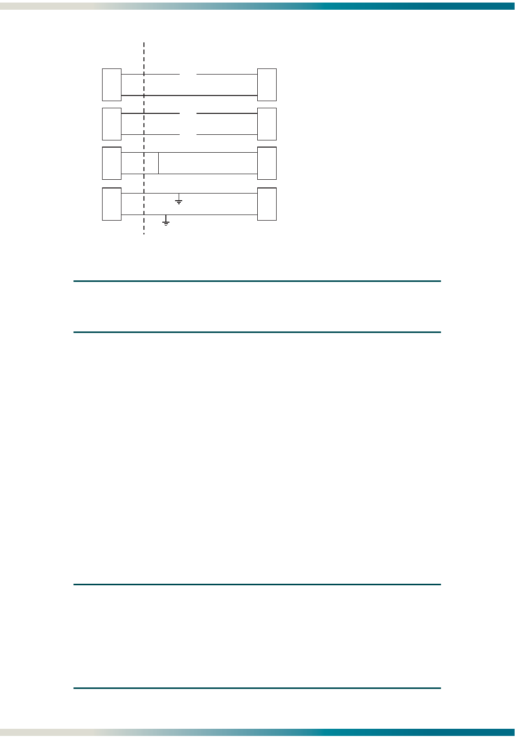
HDSL New Enhanced Feature Overview HDSL2 for General Distribution Installation and Maintenance Practice
B-2 61223HDSL2L2-5B
Figure B-1. TScan Diagnostic Capabilities
NOTE
For implementation of TScan please contact an ADTRAN sales
representative.
Splice Detection Feature
Runtime TScan 2.0TM splice detection feature is an ADTRAN proprietary non-intrusive
algorithm for detection of anomalies (bad splices) in the copper pair.
Data transmission transceivers (especially echo-cancelled technologies) are subject to perfor-
mance degradations and errors in the presence of bad splices. A splice may be benign for a
period of time, allowing a circuit to behave appropriately for portions of the day. However, over
time the splice will oxidize and incur small, rapid changes in impedance. This inconsistency in
behavior makes the problem difficult to locate. Additionally, an impedance change that is
large enough to cause the transceiver trouble may still be small enough to be undetected by
test equipment utilized on the copper pairs. Therefore a non-intrusive method of identifying
these bad splices has been developed to aid the customer in troubleshooting their distribution
plant.
NOTE
The Splice Detection Feature is included with this product as an aid
to troubleshooting. Due to inconsistency in environmental condi-
tions and their effect on telecommunications plant, ADTRAN cannot
guarantee the accuracy of the measurements. Comparison to
existing engineering drawings should provide exact locations of
suspect splices indicated by ADTRAN algorithms.
C
CO Outside Plant Facilities
ROpen on either conductor
CROpen on both conductors
CRShort between T&R
CR
Short to ground from eith
er
or both conductors
X
X
X

HDSL2 for General Distribution Installation and Maintenance Practice HDSL New Enhanced Feature Overview
61223HDSL2L2-5B B-3
The support mechanisms for this feature can logically be divided into the following six
segments:
These support mechanisms are described in the following subsections.
Splice Detection Algorithm
The splice detection algorithm is designed to detect bad splices in training mode and data
mode. The training mode detection is important if the splice is bad enough to prevent synchro-
nization. In data mode, the detector will run periodically after synchronization is achieved.
The HDSL2/HDSL4 transceiver monitors the loop for impedance changes that are of a
magnitude to cause the received signal of the transceiver to be degraded. When a significant
impedance change is detected by the transceiver, the approximate distance from that trans-
ceiver to the anomaly is recorded on the Splice Histogram screen by incrementing the appro-
priate counter. When enough counts are accumulated at a particular distance, this distance
will be reported on the Splice Results screen.
Screen Support
The craft terminal port allows access to the splice detection menus via the Troubleshooting
selection on the main menu. The Chronic Circuit Guidance selection takes the customer to
the main splice detection screen which describes the symptoms of a circuit with bad splices.
This menu provides three choices:
1. View Splice Results - This option will displays a screen that provides the results of the
splice detection tests. These results are calculated for each receiver point on the circuit. If
multiple bad splices are detected for a receiver, the worst is reported.
2. View Histogram Screen - Choosing this option will take the customer to the Histogram
Screen which displays the raw counters for each element at all receiver points.
3. Reset Splice Detector - Choosing this option will allow the customer to reset the splice
detector. This choice requires a confirmation. The reset of the detector is done locally and
the command is sent across the EOC so that all units will also reset their detectors.
EOC Support
To get full coverage of the loop, all elements in the circuit run a local detector and then
transmit the results (local histogram counts and corresponding distance buffers) of that
detection across the EOC to the terminating units (CO and RT). The terminating units then
use these counts to present a result to the customer.
FDL Support
All the information available on the troubleshooting screens is also available via the FDL,
allowing the detection to be monitored via network management utilities.
• Splice Detection Algorithm • FDL Support
• Screen Support • EEPROM Support
• EOC Support • Event Support

HDSL New Enhanced Feature Overview HDSL2 for General Distribution Installation and Maintenance Practice
B-4 61223HDSL2L2-5B
EEPROM Support
The results of the splice detector are stored to the Electronically Erasable Programmable
Read-Only Memory (EEPROM) on a daily basis at the same time the 24-hour PM registers are
stored to EEPROM. A total of 14 days splice detection history is retained. This history is read
from the EEPROM upon power up.
Event Support
An event log entry “Splice Detector Reset” is made any time the splice detector is reset. Also an
event log entry “Bad Splice Detected” is made on the first detection occurrence seen since the
last splice detection reset. This entry serves to alert the technician that a trouble has been
detected without filling up the event log.
Splice Detection Screens
Chronic Circuit Screen
The Chronic Circuit screen (Figure B-2) displays general information about circuits with bad
splices.
Figure B-2. Chronic Circuit Screen
NOTE
Since this detector employs a very sensitive measurement, it is
imperative that all obvious troubles be cleared prior to relying on the
splice detection information for troubleshooting the circuit. This is
reflected by the following screen statement: “Wire pairs pass all
electrical tests and meet deployment guidelines.”
Circuit ID: Chronic Circuit 01/09/05 11:34:00
Press ESC to return to previous menu
Chronic Circuit Problems
Field experience has shown that many chronic circuit failures are due to
bad splices. These type circuits generally have the following symptoms:
- Wire pairs pass all electrical tests and meet deployment guidelines.
- Large margin fluctuations will occur on the suspect pair. This can be seen
on the Detailed Status Screen. (Min & Max margins differ by > 6 dB)
- Pairs experience errored seconds (ES,SES,UAS) and/or loss of sync (LOS).
- The bad splice will most severely impair the unit closest to the splice.
This HDSL unit has the ability to test for bad splices. This detection
should be used as a last resort after all other loop testing has been
done. The detection is an approximation which can point the technician
to the general area of the suspect splice.(+/- 275 ft). For best
results, re-splice all splices close to the indicated trouble.
1. View Splice Results
2. View Histogram Screen
3. Reset Splice Detector

HDSL2 for General Distribution Installation and Maintenance Practice HDSL New Enhanced Feature Overview
61223HDSL2L2-5B B-5
Splices that are varying in impedance will cause the HDSL data pump to see a reduced and/or
fluctuating signal quality (margin). The HDSL data pump will attempt to track these changes,
but when the changes become too severe, errors or loss of synchronization result. This is
reflected by the symptoms described on this screen.
If a circuit meets these criteria, the possibility of an impedance-varying splice should be
considered.
Three choices are provided on the Chronic Circuit screen:
1. View Splice Results
2. View Histogram Screen
3. Reset Splice Detector
Choosing option 3 will prompt to make sure a reset is desired. If Y (yes) is chosen the splice
detector will re-initialize and start running again.
View Splice Results Screen
Selecting the View Splice Results option from the menu displays this screen (Figure B-3).
Results will be reported in the Splice Detection Results column for each transceiver:
• NTF - Reported if the unit is active and no problems have been detected or the number of
anomalies detected have not yet reached the detection count threshold, which facilitates the
reporting of the result to this screen. (Eight is the present threshold.)
• LOS - Reported if the remote unit has not been detected.
• Number - Reported if an anomaly has been detected a number of times that exceeds the
detection count threshold of eight. The number shown in this column represents the
number of feet from the transceiver (Reference Point) to that anomaly. This number will also
reflect the highest anomaly count seen, as it is possible to have more than one bad splice
per circuit. This screen will report the worst (most frequently detected) anomaly.
In this example, a detection has occurred approximately 250 feet from an H2TU-C module.
The (B) Back command will allow the technician to scroll back through the last 14 days Splice
Detection Results.

HDSL New Enhanced Feature Overview HDSL2 for General Distribution Installation and Maintenance Practice
B-6 61223HDSL2L2-5B
Figure B-3. Splice Results Screen
View Splice Histogram Screen
The View Splice Histogram Screen (Figure B-4) displays the counters that the splice detector
uses to make its result decision. For HDSL2, it displays six columns. The first and fourth
columns labeled Splice (feet) represent the distance from the respective transceiver that the
anomaly detector is evaluating. Columns 2 and 5 display the counters incremented by an
H2TU-C module when its detects an anomaly. Columns 3 and 6 display the counters incre-
mented by an H2TU-R module when its detects an anomaly.
H2TU-C and H2TU-R modules exchange this information so that the counters of each trans-
ceiver are visible locally at each end of the circuit. Since the distances that each transceiver is
evaluating may or may not be exactly the same, the Splice (feet) column reflects the distance
calculation from the displayed transceiver. To show the distances measured from the other
transceiver, press the C (Change) key. The counters on this screen are always valid for all
transceivers shown; however, the distance associated with that counter should be verified by
using the C (Change) key to get the most accurate distance.
In the example below, the distances shown are corresponding to an H2TU-C module since that
is the transceiver that has detected the anomaly. The count of 09 in the 250 feet row under
the H2TU-C column indicates that an anomaly has been seen nine times at this distance from
an H2TU-C module. Since nine exceeds the count detection threshold of eight, this result is
reported to the Splice Result Screen. Since the H2TU-R shows 00 for all counts in columns 3
and 6, there is no reason to Change (C) the view of the distance column to show the distances
an H2TU-R module is evaluating.
Circuit ID:HNTSVLALHDSL2 01/09/05 12:16:05
Press ESC to return to previous menu
* Note: Chronic Circuit Results are only valid after all other circuit *
* qualification tests have been performed and failed to show a trouble !! *
Splice Detector Version 1 Result Definitions:
---------------------------------------------
NTF - No Trouble Found yet.
LOS - Unit not in sync.
Number - Distance from Reference point (in ft.) of suspect splice.
Reference Splice Detection Version Result Shown
Point Results Number for date
--------- ---------------- ------- MM/DD/YY
H2TUC 0250 01 --------
H2TUR NTF 01 01/09/05
(B)Back
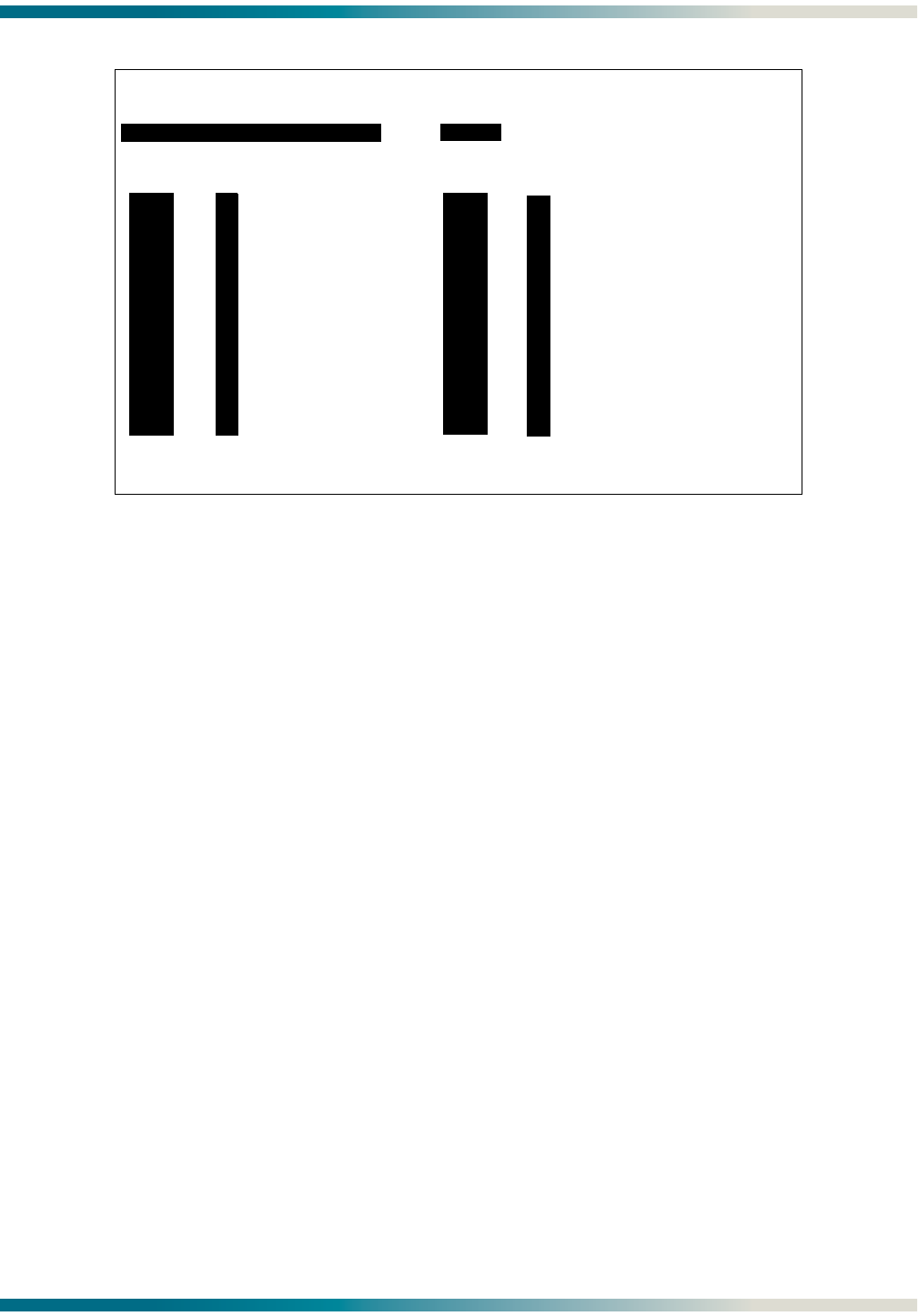
HDSL2 for General Distribution Installation and Maintenance Practice HDSL New Enhanced Feature Overview
61223HDSL2L2-5B B-7
Figure B-4. Splice Histogram Screen
Compatibility
The H2TU-C and H2TU-R both run local detectors; therefore, a splice-detection capable
H2TU-C will be able to detect bad splices up to slightly more than half the circuit length.
Likewise, a splice detection capable H2TU-R will be able to detect bad splices up to slightly
more than half the circuit from the remote end. With older (non-splice detection units) the
splice-detection capable units will not receive Embedded Operations Channel (EOC) messages
from the older units so visibility from the other end is lost. Splice detection support is not
available for two-wire repeaters.
Circuit ID: 11/05/04 09:29:45
Press ESC to return to previous menu
Splice Histogram Screen
H2TUC Press C to Change H2TUC
Splice | Splice |
(feet) | H2TUC H2TUR (feet) | H2TUC H2TUR
------ | ----- ----- ------ | ----- -----
0000 | 00 00 3890 | 00 00
0250 | 09 00 4170 | 00 00
0530 | 00 00 4455 | 00 00
0810 | 00 00 4740 | 00 00
1090 | 00 00 5025 | 00 00
1370 | 00 00 5310 | 00 00
1650 | 00 00 5595 | 00 00
1930 | 00 00 5880 | 00 00
2210 | 00 00 6165 | 00 00
2490 | 00 00 6450 | 00 00
2770 | 00 00 6735 | 00 00
3050 | 00 00 7020 | 00 00
3330 | 00 00 7305 | 00 00
3610 | 00 00 7590 | 00 00

HDSL New Enhanced Feature Overview HDSL2 for General Distribution Installation and Maintenance Practice
B-8 61223HDSL2L2-5B
Using the Bad Splice Detector
A brief synopsis of steps that might be utilized on a trouble analysis are as follows:
1. Check the HDSL units for margin fluctuation by checking the Min & Max margins on the
Detailed Span Status screen (differ by > 6 dB) corresponding to the time of the trouble.
2. Check for recorded errors (ES, SES, UAS) and/or loss of sync (LOS) in Performance
History data that also correspond to the time of the reported trouble.
3. Check that the copper pairs pass specifications using appropriate test equipment.
If copper pairs pass all tests, re-install the HDSL units. After they achieve
synchronization, clear the PM and Alarm histories from the main menu.
4. Go to the Chronic Circuit menu and reset the splice detector. (It is recommended that the
splice detector be reset after a circuit is installed to avoid inaccurate results due to old
splice-detect data left in the non-volatile memory).
5. Leave the circuit operating for a few hours or days (depending on severity of problem) and
then re-check.
6. Go to Splice Detector Results Screen and see if any indicated trouble is reported.
7. If a problem splice has been detected, re-splicing the closest splices to the indicated
trouble (±275 feet for HDSL-2 and ±550 feet for HDSL-4) is recommended.
NOTE
In general, the shorter the distance, the more accurate the mea-
surement.
8. If no trouble is reported on the Splice Detection Results Screen, go to the Histogram
screen and check for anomalies that have been detected. The anomaly can exist but may
not have reached the threshold level to report it to the Splice Detection Results Screen.
Any non-zero counter numbers on this screen may correspond to a deteriorating splice
point that should be investigated.
NOTE
If a cable pair acceptance test verified the cable pairs at turn up,
and the Splice Detector was reset at that time, then the trouble-
shooting procedure would include step 1 and step 2, then proceed
immediately with step 7 on the first trouble call.

HDSL2 for General Distribution Installation and Maintenance Practice HDSL New Enhanced Feature Overview
61223HDSL2L2-5B B-9
Event History Screen
The Event History screen (Figure B-5) shows the messages reported in the event log due to the
splice detector. Any reset of the detector is shown as well as the first detect seen since the last
reset.
Figure B-5. Event History Screen
Fault (GFI, Short) Bridging
The Fault Bridging feature minimizes circuit downtime by sustaining the circuit during the
impairment until good signal returns, thereby preventing a retrain. Downtime can occur when
an intermittent impairment (GFI, short, micro-interruption, bad splice, noise burst, etc.)
briefly affects the HDSL loop.
Fault bridging addresses two general types of problems:
• Brief power fault incidents (lightning)
• Brief signal distortions
In the older generation HDSL2 and HDSL4 transceivers, a brief short or GFI would cause a
hardware control to quickly shut down the span power supply for safety reasons. The software
would then detect the power fault and would hold the span supply off for 3 seconds. The
HDSL units would then reinitialize and retrain in approximately 25 to 30 seconds.
In the new enhanced units a combination of hardware and software enhancements allows the
units to sustain communication during brief interruptions in the span supply or brief distor-
tions of the HDSL signal. The hardware will still react to shut down the span supply for the
duration of a power fault to comply with safety requirements; however, the software will wait
much longer (150 msec of fault) before holding the span supply off. This will allow the span
power to return immediately if the power fault disappears. The hardware contains extra
capacitance to help maintain the power supply voltages during this brief interruption of span
Circuit ID: Chronic Circuit 01/09/05 13:31:36
Press ESC to return to previous menu
Num Description of Event Date Time Source
------------------------------------------------------------------------------
1. H2TU-C Event Log Reset 01/09/05 13:34:36 H2TU-C
2. H2TU-C Powered Up 01/09/05 13:30:01 H2TU-C
3. H2TU-R Powered Up 01/09/05 13:30:15 NO ID
4. Splice Detector Reset 01/09/05 13:30:29 H2TU-R
5. Bad Splice Detected 01/09/05 17:30:33 NO ID
Page Number: 1/ 1 Number of Events: 5
-------------------------------------------------------------------------
'P' - Previous Page 'H' - Home 'R' - Reset Events
'N' - Next Page 'E' - End
Selection:

HDSL New Enhanced Feature Overview HDSL2 for General Distribution Installation and Maintenance Practice
B-10 61223HDSL2L2-5B
power. When the software detects the power fault, the data pump goes into a fault bridging
mode to protect the data pump filters and to maintain service until the anomaly clears.
The software also implements the same fault bridging mode if the HDSL received signal is
distorted out on the loop during a non-power fault event (analog signal micro-interruption) to
keep the data pump stable until the anomaly clears.
Fast Retrain Feature
Fast Retrain is an ADTRAN proprietary feature whose intent is to minimize downtime when an
intermittent non power-related impairment (bad splice, noise burst, etc.) affects the HDSL
loop and cannot be bridged.
HDSL-2 and HDSL-4 transceivers normally train in approximately 25 to 30 seconds. For an
initial circuit turn-up, this is not a big issue. However, once service has been established on
the circuit, any large down-time will interrupt communications on the circuit. A loss of
synchronization on the HDSL loop can cause excessive down times due not only to the 30
second HDSL retrain time, but also further delays due to the higher level protocols in the
network going through re-synchronization. On the older generation HDSL2 and HDSL4 units,
a 1-second loss of HDSL frame synchronization would cause the data pumps to retrain. This
retrain would take approximately 25 seconds during which AIS would be sent to the termi-
nating equipment. The reception of AIS by the terminating equipment then might trigger
higher level protocol re-synchronizations.
In an effort to minimize this down time, the Fast Retrain feature has been implemented. If an
impairment (bad splice, for example) causes the HDSL data pump to lose frame synchroni-
zation for 500 msec or longer, instead of retraining, a fast retrain will be attempted. This
abbreviated train can achieve data mode in 5 to 7 seconds. A successful fast retrain should be
evident by watching the Span Status screen and by reduced unavailable seconds (UAS) in the
PM data for each LOS alarm recorded.
NOTE
Fast-Retrain capable units must be installed on both ends of the
HDSL2 circuit for this feature to function properly. Also, if there is
a failure of a fast retrain attempt, for any reason, then the tradi-
tional (25-30 second) retrain will be initiated.

61223HDSL2L2-5B C-1
Appendix C
Front Panel DSX and MUX Mode Test Access
GENERAL
Figure C-1 through Figure C-3 are DSX-1 fed modes of operation, and Figure C-4 through
Figure C-7 are MUX fed modes of operation. From the Provisioning menu (“Provisioning” on
page 22), the Network Source option is used to choose either MUX fed or DSX fed. When
performing intrusive MUX mode testing, the equipment jack on the front panel can be
configured to access the signal going to the Network or the Customer. The Equipment Jack
option, on the Loopback and Test Commands screen (“Loopbacks and Test” on page 27) is
used to configure the equipment jack for the network or customer. Every time the HTU-C is
power-cycled, it will default to the Customer direction.
DSX MODE TEST ACCESS
DSX Mode connects to the DSX (network) connector on the backplane of the chassis, where a
Multiplexer (MUX) is not utilized in the Total Access 3000 shelf.
DSX MON, Tx to Customer
The Rx of the BERT receives data from the TX MON jack (Figure C-1). This data has a monitor
jack impedance of 432 ohms and comes from the Backplane Network T1 DSX (the data that
would go toward the customer). The BERT TX is not used. This test is non-intrusive.
NOTE
The H2TU-C must be provisioned for the Out-of-Service Mainte-
nance service state when intrusive bantam jack testing is being
performed.
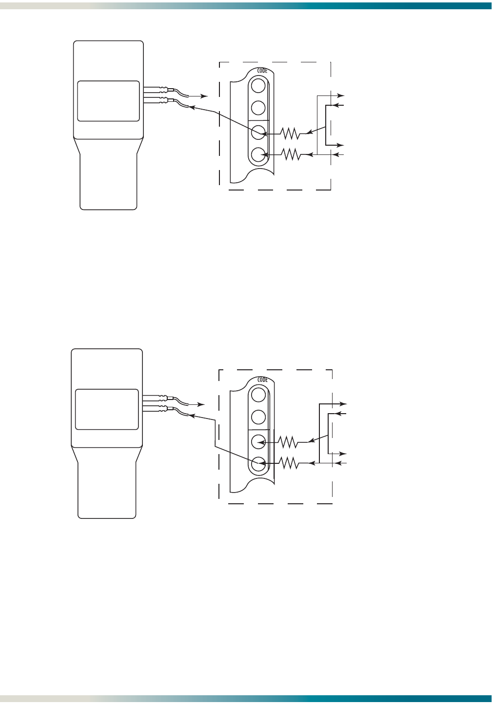
DSX Mode Test Access HDSL2 for General Distribution Installation and Maintenance Practice
C-2 61223HDSL2L2-5B
Figure C-1. DSX MON, Tx to Customer
DSX MON, Rx from Customer
The Rx of the BERT receives data from the RX MON jack (Figure C-2). This data has a monitor
jack impedance of 432 ohms and comes from the customer originated data. The BERT TX is not
used. This test is non-intrusive.
Figure C-2. DSX MON, Rx from Customer
DSX EQ, Tx to Customer, Rx from Customer
The Tx of the BERT goes to the TX EQ jack, and the Rx of the BERT goes to the RX EQ jack
(Figure C-3). The TX EQ data from the BERT is sent to the customer. The RX EQ data to the
BERT is data from the customer. The MON jack TX and RX are 432 ohm replicas of the EQ TX
and RX direct connections. This test is intrusive, as it connects the EQ jacks directly to and
from the customer data.
TX
DSX
EQ
RX
TX
DSX
MON
RX
XFrom DSX
To DSX
From CUST
To CUST
From MUX
To MUX
TX
RX
T1 BERT
432 Ω
432 Ω
TX
DSX
EQ
RX
TX
DSX
MON
RX
X
From DSX
To DSX
From CUST
To CUST
From MUX
To MUX
TX
RX
T1 BERT
432 Ω
432 Ω
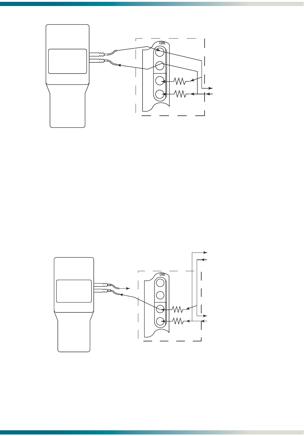
HDSL2 for General Distribution Installation and Maintenance Practice MUX Mode Test Access
61223HDSL2L2-5B C-3
Figure C-3. DSX EQ, Tx to Customer, Rx from Customer
MUX MODE TEST ACCESS
MUX Mode tests through a MUX on the Total Access 3000 shelf.
MUX MON, Tx to Customer
The Rx of the BERT receives data from the TX MON EQ jack (Figure C-4). This data is a copy of
the data that the H2TU-C will transmit to the customer. The Tx of the BERT is not used. This
test is non-intrusive.
Figure C-4. MUX MON, Tx to Customer
TX
DSX
EQ
RX
TX
DSX
MON
RX From CUST
To CUST
From MUX
To MUX
TX
RX
T1 BERT
From DSX
To DSX
432 Ω
432 Ω
TX
DSX
EQ
RX
TX
DSX
MON
RX
XFrom DSX
To DSX
From CUST
To CUST
From MUX
To MUX
TX
RX
T1 BERT
432 Ω
432 Ω
MUX Mode Test Access HDSL2 for General Distribution Installation and Maintenance Practice
C-4 61223HDSL2L2-5B
MUX MON, Rx from Customer
The Rx of the BERT receives data from the RX MON jack (Figure C-5). This data is 432 ohm
copy of the data that the H2TU-C will receive from the customer and route to the Total Access
shelf's MUX (network). The Tx of the BERT is not used. This test is non-intrusive.
Figure C-5. MUX MON, Rx from Customer
MUX EQ, Tx to Network, Rx from the Network
The Tx of the BERT is connected to the EQ TX jack, and the Rx of the BERT is connected to the
RX EQ jack (Figure C-6). The Tx of the BERT is then substituted for the data that the H2TU-C
sends to the Total Access Shelf’s MUX (network). The Rx of the BERT receives data directly
from the MUX (network). The MON TX and RX jacks are 432 ohm impedance copies of the EQ
jack TX and RX. This test is intrusive. Via the Test screen, ensure that the equipment jack is
in the To Network mode. In the To Network mode, AIS (unframed all 1’s) is sent in the customer
direction.
Figure C-6. MUX EQ, Tx to Network, Rx from Network
TX
DSX
EQ
RX
TX
DSX
MON
RX
XFrom DSX
To DSX
From CUST
To CUST
From MUX
To MUX
TX
RX
T1 BERT
432 Ω
432 Ω
TX
DSX
EQ
RX
TX
DSX
MON
RX
TX
RX
T1 BERT
From DSX
To DSX
From CUST
To CUST
From MUX
To MUX
432 Ω
432 Ω
HDSL2 for General Distribution Installation and Maintenance Practice MUX Mode Test Access
61223HDSL2L2-5B C-5
MUX EQ, Tx to Customer, Rx from Customer
The Tx of the BERT is connected to the EQ TX jack, and the Rx of the BERT is connected to the
RX EQ jack (Figure C-7). The Tx of the BERT is then substituted for the data that the H2TU-C
sends to the customer. The Rx of the BERT receives data directly from the customer. The MON
TX and RX jacks are 432 ohm impedance copies of the EQ jack TX and RX. This test is
intrusive. Via the Test screen, ensure that the equipment jack is in the To Customer mode. In
the To Customer mode, AIS (unframed all 1’s) is sent in the network direction.
Figure C-7. MUX EQ, Tx to Customer, Rx from Customer
TX
DSX
EQ
RX
TX
DSX
MON
RX
TX
RX
T1 BERT
From DSX
To DSX
From Selected CUST
To Selected CUST
From MUX
To MUX
432 Ω
432 Ω

MUX Mode Test Access HDSL2 for General Distribution Installation and Maintenance Practice
C-6 61223HDSL2L2-5B
This page is intentionally blank.

61223HDSL2L2-5B D-1
Appendix D
Warranty
WARRANTY AND CUSTOMER SERVICE
ADTRAN will replace or repair this product within the warranty period if it does not meet its
published specifications or fails while in service. Warranty information can be found at
www.adtran.com/warranty.
Refer to the following subsections for sales, support, Customer and Product Service (CAPS)
requests, or further information.
ADTRAN Sales
Pricing/Availability:
800-827-0807
ADTRAN Technical Support
Pre-Sales Applications/Post-Sales Technical Assistance:
800-726-8663
Standard hours: Monday - Friday, 7 a.m. - 7 p.m. CST
Emergency hours: 7 days/week, 24 hours/day
ADTRAN Repair/CAPS
Return for Repair/Upgrade:
(256) 963-8722
Repair and Return Address
Contact CAPS prior to returning equipment to ADTRAN.
ADTRAN, Inc.
CAPS Department
901 Explorer Boulevard
Huntsville, Alabama 35806-2807

Carrier Networks Division
901 Explorer Blvd.
Huntsville, AL 35806
®
