Adtran Network Router Dsu 56 Users Manual 64
DSU 56-64 User Manual DSU 56-64 User Manual
DSU_56_64_User_Manua.. DSU_56_64_User_Manual
DSU 56 to the manual 805f99fd-479a-4d60-b16f-3792d1d1c120
2015-01-24
: Adtran Adtran-Network-Router-Dsu-56-Users-Manual-345216 adtran-network-router-dsu-56-users-manual-345216 adtran pdf
Open the PDF directly: View PDF ![]() .
.
Page Count: 44

DSU 56/64
Data Service Unit
User Manual
Part Number 1200062L1
61200062L1-1E
May 2001

901 Explorer Boulevard
P.O. Box 140000
Huntsville, AL 35814-4000
(256) 963-8000
© 2001 ADTRAN, Inc.
All Rights Reserved.
Printed in U.S.A.
iii
The following conventions are used in this manual.
Important Safety Instructions
When using your telephone equipment, please follow these basic safety precautions
to reduce the risk of fire, electrical shock, or personal injury:
1. Do not use this product near water, such as near a bathtub, wash bowl, kitchen
sink, laundry tub, in a wet basement, or near a swimming pool.
2. Avoid using a telephone (other than a cordless-type) during an electrical storm.
There is a remote risk of shock from lightning.
3. Do not use the telephone to report a gas leak in the vicinity of the leak.
4. Use only the power cord, power supply, and/or batteries indicated in the manual.
Do not dispose of batteries in a fire. They may explode. Check with local codes for
special disposal instructions.
Save These Important Safety Instructions
Notes provide additional useful information.
Cautions signify information that could prevent service interruption.
Warnings provide information that could prevent damage to the equip-
ment or endangerment to human life.

iv
Affidavit Requirements for Connection to Digital Services
• An affidavit is required to be given to the telephone company whenever digital
terminal equipment without encoded analog content and billing protection is
used to transmit digital signals containing encoded analog content which are
intended for eventual conversion into voice band analog signal and transmitted
on the network.
• The affidavit shall affirm that either no encoded analog content or billing informa-
tion is being transmitted or that the output of the device meets Part 68 encoded
analog content or billing protection specification.
• End user/customer will be responsible to file an affidavit with the local exchange
carrier when connecting unprotected CPE to a 1.544 Mbps or subrate digital ser-
vice.
• Until such time as subrate digital terminal equipment is registered for voice appli-
cations, the affidavit requirements for subrate services are waived.

v
Affidavit for Connection of Customer Premises Equipment to 1.544 MBPS and/
or Subrate Digital Services
For the work to be performed in the certified territory of ______________ (telco name)
State of ________________________________
County of ______________________________
I, _______________________ (name), ____________________ (business address),
_____________________ (telephone number) being duly sworn, state:
I have the responsibility for the operation and maintenance of the terminal equipment
to be connected to 1.544 Mbps and/or __________________ subrate digital services.
The terminal equipment to be connected complies with Part 68 of the FCC rules
except for the encoded analog content and billing protection specification. With
respect to encoded analog content and billing protection:
( ) I attest that all operations associated with the establishment, maintenance and adjust-
ment of the digital CPE with respect to encoded analog content and billing protection
information continuously complies with Part 68 of the FCC rules and Regulations.
( ) The digital CPE does not transmit digital signals containing encoded analog con-
tent or billing information which is intended to be decoded within the telecommuni-
cations network.
( ) The encoded analog content and billing protection is factory set and is not under
the control of the customer.
I attest that the operator(s) maintainer(s) of the digital CPE responsible for the estab-
lishment, maintenance and adjustment of the encoded analog content and billing
information has (have) been trained to perform these functions by successfully having
completed one of the following (check appropriate blocks):
( ) A. A training course provided by the manufacturer/grantee of the equipment used
to encode analog signals; or
( ) B. A training course provided by the customer or authorized representative, using
training materials and instructions provided by the manufacturer/grantee of the
equipment used to encode analog signals; or
( ) C. An independent training course (e.g., trade school or technical institution) rec-
ognized by the manufacturer/grantee of the equipment used to encode analog sig-
nals; or

vi
( ) D. In lieu of the proceeding training requirements, the operator(s)/maintainer(s) is
(are) under the control of a supervisor trained in accordance with _______________
(circle one) above.
I agree to provide ____________________ (telco’s name) with proper documentation
to demonstrate compliance with the information in the preceding paragraph, if so
requested.
_____________________ Signature
_____________________ Title
_____________________ Date
Subscribed and sworn to before me
This _________ day of ___________________, 20__
_______________________________________
Notary Public
My commission expires: _________________________

vii
FCC regulations require that the following information be provided in this manual:
1. This equipment complies with Part 68 of the FCC rules. On the bottom of the
equipment housing is a label that shows the FCC registration number and Ringer
Equivalence Number (REN) for this equipment, if applicable. If required, this
information must be given to the telephone company.
2. The following information may be required when applying to the local telephone
company for leased line facilities.
3. An FCC compliant telephone cord with a modular plug may be provided with
this equipment. This equipment is designed to be connected to the telephone net-
work or premises wiring using a compatible modular jack, which is FCC Part 68
compliant. See Chapter 2, Installation on page 2-1 for details.
4. If this equipment causes harm to the telephone network, the telephone company
may temporarily discontinue service. If possible, advance notification is given;
otherwise, notification is given as soon as possible. The telephone company will
advise the customer of the right to file a complaint with the FCC.
5. The telephone company may make changes in its facilities, equipment, operations,
or procedures that could affect the proper operation of this equipment. If this hap-
pens, the telephone company will provide advance notification and the opportunity
to make the necessary modifications to maintain uninterrupted service.
6. If experiencing difficulty with this equipment, please contact ADTRAN for repair and
warranty information. If the equipment is causing harm to the network, the telephone
company may request this equipment to be disconnected from the network until the
problem is resolved or it is certain that the equipment is not malfunctioning.
7. This unit contains no user serviceable parts.
8. The FCC recommends that the AC outlet to which equipment requiring AC
power is to be installed is provided with an AC surge arrester.
Service Type Digital Facility
Interface Code Service Order Code Network
Jacks
56 kbps Digital Interface 04DU5-56 6.0F RJ-48S

viii
Federal Communications Commission Radio Frequency Interference Statement
This equipment has been tested and found to comply with the limits for a Class A dig-
ital device, pursuant to Part 15 of the FCC Rules. These limits are designed to provide
reasonable protection against harmful interference when the equipment is operated in
a commercial environment. This equipment generates, uses, and can radiate radio fre-
quency energy and, if not installed and used in accordance with the instruction man-
ual, may cause harmful interference to radio frequencies. Operation of this equipment
in a residential area is likely to cause harmful interference in which case the user will
be required to correct the interference at his own expense.
Shielded cables must be used with this unit to ensure compliance with Class A FCC
limits.
Canadian Emissions Requirements
This digital apparatus does not exceed the Class A limits for radio noise emissions
from digital apparatus as set out in the interference-causing equipment standard enti-
tled “Digital Apparatus," ICES-003 of the Department of Communications.
Cet appareil nuerique respecte les limites de bruits radioelectriques applicables aux
appareils numeriques de Class A prescrites dans la norme sur le materiel brouilleur:
"Appareils Numeriques," NMB-003 edictee par le ministre des Communications.
Change or modifications to this unit not expressly approved by the party re-
sponsible for compliance could void the user’s authority to operate the equip-
ment.

ix
Canadian Equipment Limitations
Notice: The Canadian Industry and Science Canada label identifies certified equip-
ment. This certification means that the equipment meets certain telecommunications
network protective, operational, and safety requirements. The Department does not
guarantee the equipment will operate to the user’s satisfaction.
Before installing this equipment, users should ensure that it is permissible to be con-
nected to the facilities of the local telecommunications company. The equipment must
also be installed using an acceptable methods of connection. In some cases, the com-
pany’s inside wiring associated with a single line individual service may be extended
by means of a certified connector assembly (telephone extension cord). The customer
should be aware that compliance with the above limitations may not prevent degra-
dation of service in some situations.
Repairs to certified equipment should be made by an authorized Canadian mainte-
nance facility designated by the supplier. Any repairs or alterations made by the user
to this equipment, or equipment malfunctions, may give the telecommunications
company cause to request the user to disconnect the equipment.
Users should ensure for their own protection that the electrical ground connections of
the power utility, telephone lines and internal metallic water pipe system, if present,
are connected together. This precaution may be particularly important in rural areas.
The Load Number (LN) assigned to each terminal device denotes the percentage of
the total load to be connected to a telephone loop which is used by the device, to pre-
vent overloading. The termination on a loop may consist of any combination of
devices subject only to the requirement that the total of the Load Numbers of all
devices does not exceed 100.
Users should not attempt to make such connections themselves, but
should contract the appropriate electric inspection authority, or an elec-
trician, as appropriate.

x
Limited Product Warranty
ADTRAN warrants that for five (5) years from the date of shipment to Customer, all
products manufactured by ADTRAN will be free from defects in materials and work-
manship. ADTRAN also warrants that products will conform to the applicable speci-
fications and drawings for such products, as contained in the Product Manual or in
ADTRAN's internal specifications and drawings for such products (which may or
may not be reflected in the Product Manual). This warranty only applies if Customer
gives ADTRAN written notice of defects during the warranty period. Upon such
notice, ADTRAN will, at its option, either repair or replace the defective item.
If ADTRAN is unable, in a reasonable time, to repair or replace any equipment to a
condition as warranted, Customer is entitled to a full refund of the purchase price
upon return of the equipment to ADTRAN. This warranty applies only to the original
purchaser and is not transferable without ADTRAN's express written permission.
This warranty becomes null and void if Customer modifies or alters the equipment in
any way, other than as specifically authorized by ADTRAN.
EXCEPT FOR THE LIMITED WARRANTY DESCRIBED ABOVE, THE FOREGOING
CONSTITUTES THE SOLE AND EXCLUSIVE REMEDY OF THE CUSTOMER AND
THE EXCLUSIVE LIABILITY OF ADTRAN AND IS IN LIEU OF ANY AND ALL
OTHER WARRANTIES (EXPRESSED OR IMPLIED). ADTRAN SPECIFICALLY DIS-
CLAIMS ALL OTHER WARRANTIES, INCLUDING (WITHOUT LIMITATION),
ALL WARRANTIES OF MERCHANTABILITY AND FITNESS FOR A PARTICULAR
PURPOSE. SOME STATES DO NOT ALLOW THE EXCLUSION OF IMPLIED WAR-
RANTIES, SO THIS EXCLUSION MAY NOT APPLY TO CUSTOMER.
In no event will ADTRAN or its suppliers be liable to Customer for any incidental,
special, punitive, exemplary or consequential damages experienced by either Cus-
tomer or a third party (including, but not limited to, loss of data or information, loss
of profits, or loss of use). ADTRAN is not liable for damages for any cause whatsoever
(whether based in contract, tort, or otherwise) in excess of the amount paid for the
item. Some states do not allow the limitation or exclusion of liability for incidental or
consequential damages, so the above limitation or exclusion may not apply to Cus-
tomer.

xi
Customer Service, Product Support Information, and Training
ADTRAN will replace or repair this product within five years from the date of ship-
ment if the product does not meet its published specification, or if it fails while in ser-
vice.
A return material authorization (RMA) is required prior to returning equipment to
ADTRAN. For service, RMA requests, training, or more information, see the toll-free
contact numbers given below.
Presales Inquiries and Applications Support
Please contact your local distributor, ADTRAN Applications Engineering, or ADT-
RAN Sales:
Post-Sale Support
Please contact your local distributor first. If your local distributor cannot help, please
contact ADTRAN Technical Support and have the unit serial number available.
The Custom Extended Services (ACES) program offers multiple types and levels of ser-
vice plans which allow you to choose the kind of assistance you need. For questions,
call the ACES Help Desk.
Repair and Return
If ADTRAN Technical Support determines that a repair is needed, Technical Support
will coordinate with the Custom and Product Service (CAPS) department to issue an
RMA number. For information regarding equipment currently in house or possible
fees associated with repair, contact CAPS directly at the following number:
Applications Engineering (800) 615-1176
Sales (800) 827-0807
Technical Support (888) 4ADTRAN
ACES Help Desk (888) 874-2237
CAPS Department (256) 963-8722

xii
Identify the RMA number clearly on the package (below address), and return to the fol-
lowing address:
ADTRAN Customer and Product Service
901 Explorer Blvd.
Huntsville, Alabama 35806
RMA # _____________
Training
The Enterprise Network (EN) Technical Training Department offers training on our
most popular products. These courses include overviews on product features and func-
tions while covering applications of ADTRAN's product lines. ADTRAN provides a va-
riety of training options, including customized training and courses taught at our
facilities or at your site. For more information about training, please contact your Terri-
tory Manager or the Enterprise Training Coordinator.
Training - phone (800) 615-1176, ext. 7500
Training - fax (256) 963 7941
Training - email training@adtran.com

61200062L1-1 DSU 56/64 User Manual xiii
Table of Contents
List of Figures ...................................................................................................................... xv
List of Tables ......................................................................................................................xvii
Chapter 1. Introduction
Product Overview ...............................................................................................................1-1
Front Panel ...........................................................................................................................1-2
LED Identification .................................................................................................1-2
DTE Status (Green) ........................................................................................1-2
Network Status (Red) ....................................................................................1-2
Test Status/Error (Yellow/Red) ..................................................................1-3
Test Switches .........................................................................................................1-3
Rear Panel .............................................................................................................................1-4
Chapter 2. Installation
Unpack, Inspect, Power Up ...............................................................................................2-1
Contents of Shipping Package ....................................................................................2-1
Customer Provides.......................................................................................................2-1
Power Up........................................................................................................................2-2
Configuration .......................................................................................................................2-2
Clear To Send (CS) - SW 1 ...................................................................................2-2
Down - Normal ..............................................................................................2-2
Up - On ............................................................................................................2-2
Clear to Send Delay (CS Delay) - SW 2 ..............................................................2-2
Switch Position ...............................................................................................2-2
Down - Short ..................................................................................................2-2
Up - Long ........................................................................................................2-2
Antistream - SW 3 .................................................................................................2-3
Down - Off ......................................................................................................2-3
Up - On ............................................................................................................2-3

Table of Contents
xiv DSU 56/64 User Manual 61200062L1-1
Carrier Detect (CD) - SE 4 ....................................................................................2-3
Down - Normal ..............................................................................................2-3
Up - On ............................................................................................................2-3
Data Set Ready (SR) - SW 5 ..................................................................................2-3
Down - On .......................................................................................................2-3
Up - Normal ....................................................................................................2-3
Remote Digital Loopback (RDL) - SW 6 ............................................................2-4
Down - Enable ................................................................................................2-4
Up - Disable ....................................................................................................2-4
Loop Rate - SW 7 ...................................................................................................2-4
Down - 56 Kbps ..............................................................................................2-4
Up - 64 kbps ....................................................................................................2-4
Scrambler - SW 8 ...................................................................................................2-4
Down - On .......................................................................................................2-4
Up - Off ............................................................................................................2-4
Network Connections .........................................................................................................2-5
DTE Connections .................................................................................................................2-5
Chapter 3. Test Modes
Self Test .................................................................................................................................3-1
Near End Tests .....................................................................................................................3-2
DTE Only Test ......................................................................................................................3-2
DTE with Test Pattern (TP) ................................................................................................3-3
DTE and Loop Test (LL) .....................................................................................................3-4
Loop Only Test (RT) ............................................................................................................3-6
Far End Tests ........................................................................................................................3-7
Remote Digital...............................................................................................................3-7
RDL with Test Pattern (TP)..........................................................................................3-7
Test Pattern (PTRN)......................................................................................................3-8
Remote Tests ........................................................................................................................3-9
Appendix A. Pinouts........................................................................................................ A-1
Appendix B. Specifications............................................................................................ B-1
Index ............................................................................................................................Index-1

61200062L1-1 DSU 56/64 User Manual xv
List of Figures
Figure 1-1. DSU 56/64 Unit ..............................................................................................1-2
Figure 1-2. DSU 56/64 Rear Panel...................................................................................1-4
Figure 3-1. DTE Only Test Diagram.................................................................................3-2
Figure 3-2. DTE with TP Test Diagram ...........................................................................3-4
Figure 3-3. DTE and Loop Test Diagram ........................................................................3-5
Figure 3-4. Loop Only Test Diagram ...............................................................................3-6

List of Figures
xvi DSU 56/64 User Manual 61200062L1-1

61200062L1-1 DSU 56/64 User Manual xvii
List of Tables
Table 2-1. Default Option Switch Settings....................................................................2-5
Table A-1. Pinouts for RJ-48S Network Connections..................................................A-1
Table A-2. V.35 DTE Pinouts...........................................................................................A-2

List of Tables
xviii DSU 56/64 User Manual 61200062L1-1

61200062L1-1 DSU 56/64 User Manual 1-1
Chapter 1 Introduction
PRODUCT OVERVIEW
The ADTRAN DSU 56/64, shown in Figure 1-1 on page 1- 2, is a
technologically advanced, high performance Data Service/Channel
Service Unit (DSU/CSU) that provides the interface between telco
provided Digital Data Service (DDS) and the customer’s Data
Terminal Equipment (DTE).
The DSU 56/64 supports both 56 kbps and 64 kbps loop service
rates with the DTE interface rate matching the selected loop rate. A
synchronous V.35 interface is provided for the DTE interface.
All setup or configuration is accomplished with a single eight-
position DIP switch that is accessible from the back panel of the
unit.

Chapter 1. Introduction
1-2 DSU 56/64 User Manual 61200062L1-1
FRONT PANEL
As shown in Figure 1-1, the front panel of the DSU 56/64 contains
eleven light emitting diode (LED) indicators that display DTE
interface, network, and test status. These indicators are defined in
the LED Identification section, below.
Figure 1-1. DSU 56/64 Unit
LED Identification
DTE Status (Green)
Network Status (Red)
SELECT
ERRORPTRNRDL
TEST
LOOPDTE
TEST
DSU 56/64
CDRDTDCSRS ALM
Indicator Definition Source
RS
CS
TD
RD
CD
Request To Send
Clear To Send
Transmit Data
Receive Data
Carrier Detect
DTE
DSU
DTE
DSU
DSU
The active state for the status indicators (RS, CS, and CD) is On while
the on state for the data indicators (TD and RD) represents a Space con-
dition.
ALM ON indicates a problem on the local loop or within the
DDS network.
OFF indicates normal loop and network conditions.

Chapter 1. Introduction
61200062L1-1 DSU 56/64 User Manual 1-3
Test Status/Error (Yellow/Red)
Tests defined by the above indicators are explained in greater detail
in Chapter 3, Test Modes on page 3-1.
Test Switches
The front panel also contains two push-button switches for
selecting and controlling the various test modes for the DSU 56/64.
The descriptions of these switches are as follows:
DTE ON SOLID indicates DTE interface test in progress.
FLASHING indicates Loop Interface test (CSU Loop-
back) has been initiated by telco.
Loop ON SOLID indicates loop interface test has been initiat-
ed from local DSU.
FLASHING indicates loop interface test (CSU or DSU
Loopback) has been initiated by telco.
RDL ON SOLID indicates remote digital loopback test has
been initiated from the local DSU.
FLASHING indicates remote digital loopback test has
been initiated from the remote DSU.
PTRN ON SOLID indicates that integral pattern generator is
being utilized for testing.
Error ON indicates that errors are being detected during a
test or that a test can not be properly initiated.
Select Each time this switch is activated, a valid test mode is in-
dicated by one or more LEDs being turned on solid.
Pressing the SELECT button from within an active test in-
jects a bit error.
Test Once the desired test mode is displayed on the test sta-
tus indicators, the test is initiated by activating this
switch. Pressing the TEST button again will terminate
any test in progress.
Chapter 1. Introduction
1-4 DSU 56/64 User Manual 61200062L1-1
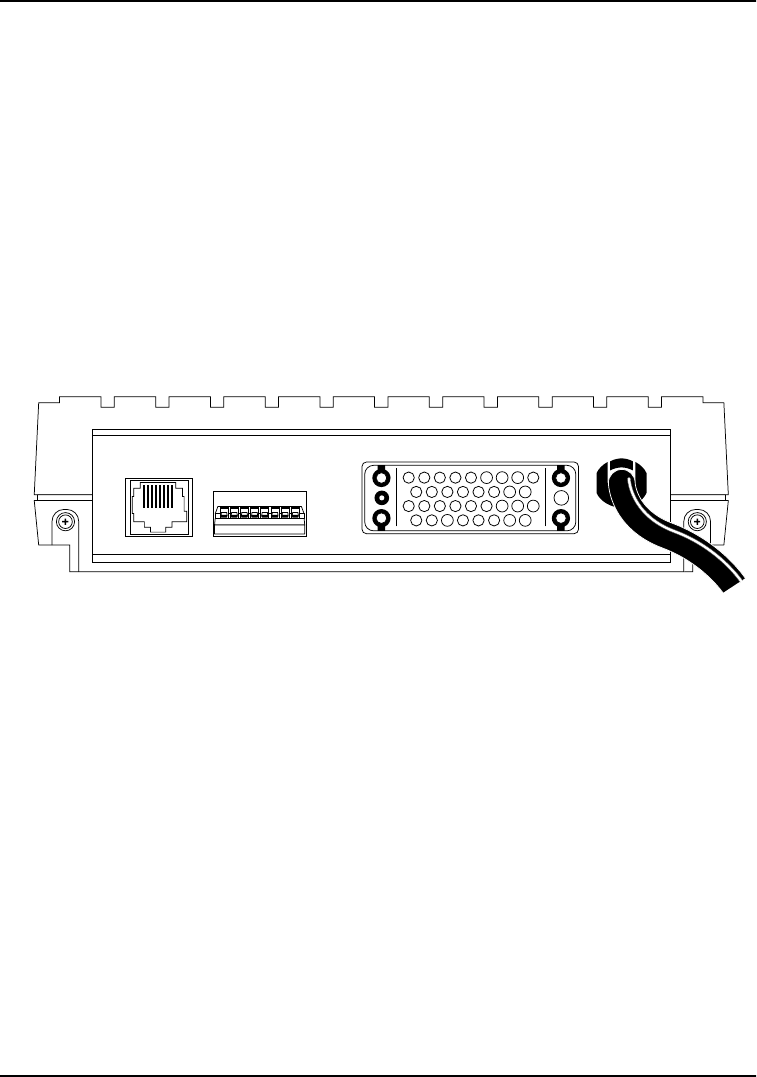
REAR PANEL
The rear panel of the DSU 56/64 is shown in Figure 1-2.
PRIMARY V.35, a thirty-four pin connector, provides the
synchronous DTE interface.
The eight-pin modular jack (RJ-48S) labeled TELCO connects the
DSU 56/64 to the DDS network.
For pinouts to these connectors, see Table A-1, Pinouts for RJ-48S
Network Connections, on page A-1 and Table A-2, V.35 DTE Pinouts,
on page A-2.
Figure 1-2. DSU 56/64 Rear Panel
All setup or configuration parameters for the DSU 56/64 are
selected with an eight-position DIP switch. This switch, labeled
OPTIONS, is accessible from the rear panel. The label also references
the options chart located on the bottom of the unit. The individual
options are explained in detail in Chapter 2 in the section
Configuration on page 2-2.
The power cord on the rear panel of the DSU 56/64 is mechanically
secured to the back panel and provides the connections to the
integral AC/DC power supply.
12345678 115 VAC
60HZ .06A
TELCO OPTIONS
(LISTED ON BOTTOM)
PRIMARY V.35

61200062L1-1 DSU 56/64 User Manual 2-1
Chapter 2 Installation
UNPACK, INSPECT, POWER UP
Carefully inspect the DSU 56/64 for any shipping damages. If
damage is suspected, file a claim immediately with the carrier and
then contact ADTRAN Customer and Product Service (CAPS). If
possible, keep the original shipping container for use in returning
the unit for repair or for verification of damage during shipment.
Contents of Shipping Package
The following items are included in ADTRAN shipments of the
DSU 56/64:
• The DSU 56/64 unit
• Network interface cable
• An 8-position modular to 8-position modular cable
• The DSU 56/64 User Manual
Customer Provides
•V.35 cable

Chapter 2. Installation
2-2 DSU 56/64 User Manual 61200062L1-1
Power Up
The DSU 56/64 is equipped with a captive six-foot power cord that
is terminated with a three-prong plug for connecting to a grounded
power receptacle.
CONFIGURATION
The DSU 56/64 has eight options for controlling the operation of
both the network and DTE interfaces. These options are selected by
setting individual switches on either position DIP switch that is
accessible from the rear panel. A chart showing the options and
switch settings is attached to the bottom of the unit.
Clear To Send (CS) - SW 1
Down - Normal
In the down position, CS follows the RS lead with the selected
amount of delay. The only exceptions to this occur when network
or test conditions prevent data from being transferred over the DTE
interface. During these conditions CS is turned off.
Up - On
CS is forced on all the time.
Clear to Send Delay (CS Delay) - SW 2
Switch Position
RS to CS Delay
Down - Short
250 µs + 125 µs
Up - Long
10 ms + 125 µs
Ensure that a grounded, 115 VAC, 60 Hz receptacle is used for powering
the DSU 56/64 unit.

Chapter 2. Installation
61200062L1-1 DSU 56/64 User Manual 2-3
Antistream - SW 3
The Antistream option is used to select the antistream time out. The
antistream time out is the maximum time the DSU 56/64 is allowed
to transmit data from the DTE into the network. This feature
prevents one DTE device on a multi-drop network from
continuously tying up the transmit circuit from a remote DSU back
to the master DSU.
The antistream timer is reset to zero when RS transitions to the
active state and is updated every second while RS is active. When
the antistream time out expires, the DSU 56/64 stops transmitting
DTE data into the network. It does, however, continue to accept
data. CS is maintained in the active state until the DTE deactivates
the RS input.
Down - Off
The Antistream timer is disabled.
Up - On
The Antistream timer is enabled and set for 45 +/- 0.5 seconds.
Carrier Detect (CD) - SE 4
Down - Normal
CD is on any time customer data is being received and off when the
receive circuit is idle, not carrying customer data.
Up - On
CD is forced on all the time.
Data Set Ready (SR) - SW 5
Down - On
SR is forced on all the time.
Up - Normal
SR is only turned off when the network is out of service or a test is
in progress.

Chapter 2. Installation
2-4 DSU 56/64 User Manual 61200062L1-1
Remote Digital Loopback (RDL) - SW 6
Down - Enable
The DSU 56/64 accepts the industry standard V.54 RDL command
from the far end of the circuit.
Up - Disable
The DSU 56/64 does not respond to the V.54 loopback command
from the far end of the circuit.
Loop Rate - SW 7
Down - 56 Kbps
The network interface of the DSU 56/64 is configured for operation
at 56 kbps.
Up - 64 kbps
The network interface is configured for 64 kbps operation.
Scrambler - SW 8
For 64 kbps clear channel operation, there is a possibility that the
DTE data sequenced might mimic network loop maintenance
functions and erroneously cause other network elements to activate
loopbacks. To prevent this, the Scrambler switch should be set to
the Down (On) position.
The SCRAMBLER ON option must be set the same for both the local
and remote 56/64 DSUs for the situation described above.
The option is only valid when the 64 kbps rate is selected.
Down - On
The scrambler is enabled.
Up - Off
The scrambler is disabled.
Chapter 2. Installation
61200062L1-1 DSU 56/64 User Manual 2-5
NETWORK CONNECTIONS
This interface consists of four leads that are paired to provide
separate transmit and receive circuits. The four leads are provided
on the eight-position modular jack DSU RJ-48S labeled TELCO on
the rear panel of the DSU 56/64.
The pinouts for this connector are shown in Table A-1 on page A-1.
DTE CONNECTIONS
The Data Terminal Equipment (DTE) is attached to the connector
labeled PRIMARY V.35 at the rear of the DSU 56/64.
The pinout for the V.35 DTE connector is shown in Table A-2 on
page A-2.
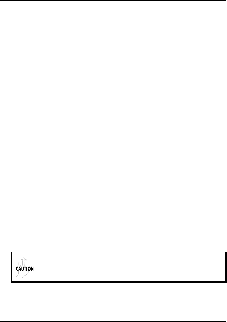
Table 2-1. Default Option Switch Settings
Switch Position Setting
1
2
3
4
5
6
7
8
Down
Down
Down
Down
Up
Down
Down
Down
Clear to Send (CS) Normal
CS Delay Short
Anti-stream Timer Off
Carrier Detect (CD) Normal
Data Set Ready (SR) Normal
Remote Digital Loopback (RDL) Enabled
Loop Rate 56 Kbps
Scrambler Enabled
A shielded V.35 cable is required to prevent possible radio frequency in-
terference emissions.

Chapter 2. Installation
2-6 DSU 56/64 User Manual 61200062L1-1

61200062L1-1 DSU 56/64 User Manual 3-1
Chapter 3 Test Modes
In addition to a self-test mode, the DSU 56/64 has other extensive
test modes which are designed to help isolate problems to specific
components of the communications circuit. These various test
modes for the DSU 56/64 are initiated and terminated from the
front panel using the SELECT and TEST buttons.
SELF TEST
A self-test goes through the following cycle.
1. When the DSU 56/64 is powered on, all LEDs on the front
panel turn on simultaneously for approximately two seconds.
2. After two seconds, all the LEDs turn off briefly.
3. The LEDs then cycle on in pairs with a fan-out pattern away
from the ALM indicator.
4. Next, the LEDs cycle off in pairs with a fan-in pattern back
towards the ALM indicator.
These patterns are repeated four times for visual verification that
all LEDs are functioning properly.
At the completion of the LED test patterns, the PTRN LED is on,
which indicates that the DTE with TP test is being performed.
If the test is successful, the ERROR indicator does not turn on.
If the DTE WITH TP test fails, the RS, ALM, DTE, PTRN, and ERROR
indicators all flash.
Chapter 3. Test Modes
3-2 DSU 56/64 User Manual 61200062L1-1
If an EPROM CHECKSUM failure is detected during self test, CS,
ALM, PTRN, and ERROR indicators all flash at the end of the self
test.
NEAR END TESTS
The local DSU 56/64 can perform the following near end tests:
•DTE Only
• DTE with Test Pattern
• DTE and LOOP (LL)
• Loop Only (RT)
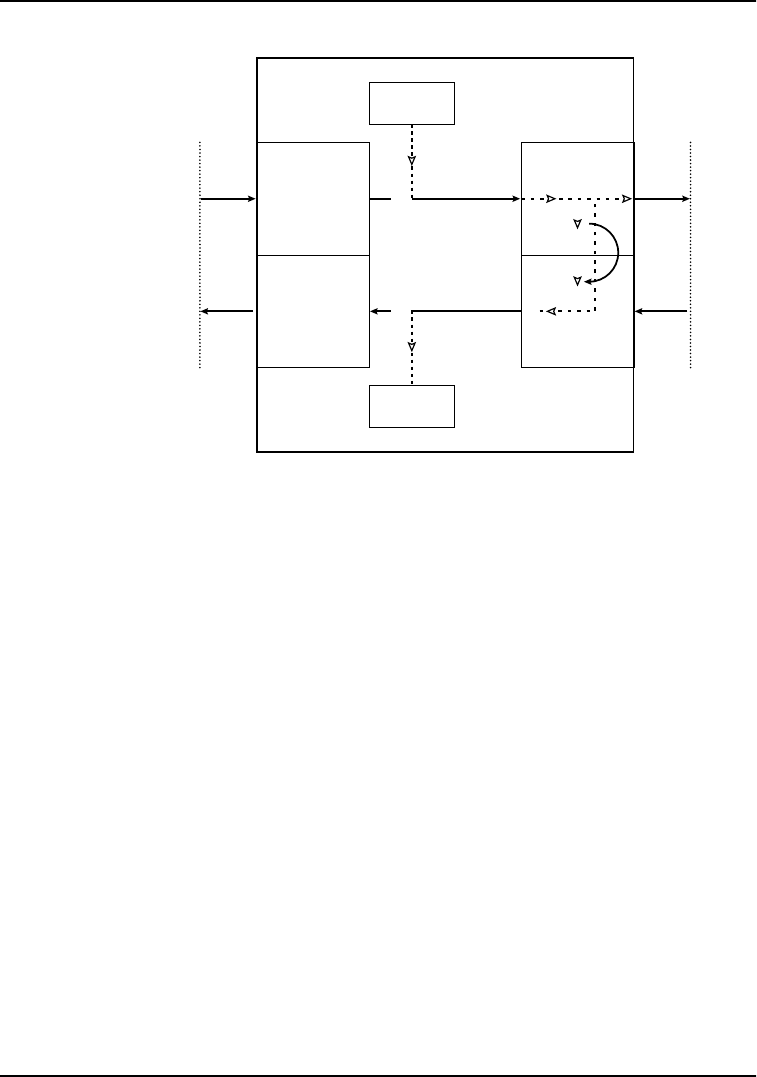
DTE ONLY TEST
The DTE ONLY test can test both the DTE interface of the local DSU
56/64 plus its loop transmitter and receiver. For this test, the loop
transmit data is connected to the loop receive data at a point close
to the physical network interface.
The loopback point and the signal paths for this test are shown in
Figure 3-1.
Figure 3-1. DTE Only Test Diagram
56/64 DSU
DTE
Receive
Interface
DTE
Transmit
Interface
Loop
Transmit
Interface
Loop
Receive
Interface
DTE
Only
TD
DTE or Test
Equipment
Interface
Network
Interface
RD
Loop TX
Loop RX

Chapter 3. Test Modes
61200062L1-1 DSU 56/64 User Manual 3-3
To initiate the DTE ONLY test, perform the following steps:
1. Press SELECT once to turn on the DTE test indicator.
2. Press TEST while the test indicator is on.
3. To terminate the test, press TEST.
Test data from the terminal or test equipment is routed through the
DTE section of the DSU 56/64 and then to the output of the loop
transmitter section where the signal is encoded for transmission.
The output of the loop transmitter is coupled back to the loop
receiver input. The received test signal is then decoded and
returned to the terminal or test equipment where it is checked for
any bit errors.
DTE WITH TEST PATTERN (TP)
The DTE WITH TP test is similar to the DTE ONLY TEST described in
Figure 3-1 on page 3-2. It is initiated at the local DSU 56/64 and is
used to independently test the operation of the DSU 56/64.
To initiate the DTE WITH TP test, perform the following steps:
1. Press SELECT twice to turn on both the DTE and PTRN test
indicators.
2. Press TEST while these test indicators are on.
3. To terminate this test, press TEST.
Instead of using data from the terminal or test equipment, this test
utilizes an internal test pattern generator and detector in the DSU
56/64. The loopback point and the data paths for this test are
illustrated in Figure 3-2 on page 3-4.
Chapter 3. Test Modes
3-4 DSU 56/64 User Manual 61200062L1-1
Figure 3-2. DTE with TP Test Diagram
The internal test pattern generator and detector of the DSU 56/64
operate with a 2047 data pattern. When this test is initiated, the test
pattern detector examines the receive data stream until
synchronization to the 2047 pattern occurs. Once synchronized, the
detector continues to check the receive data and reports any
detected bit errors by turning on the ERROR LED.
Once a test is initialized with the internal test pattern generator and
detector, errors can be injected into the transmit data stream by
pressing SELECT and observed by watching the ERROR LED turn
on for a brief period of time. As previously mentioned, the DTE
WITH TP is automatically performed during the self-test sequence
for the DSU 56/64.
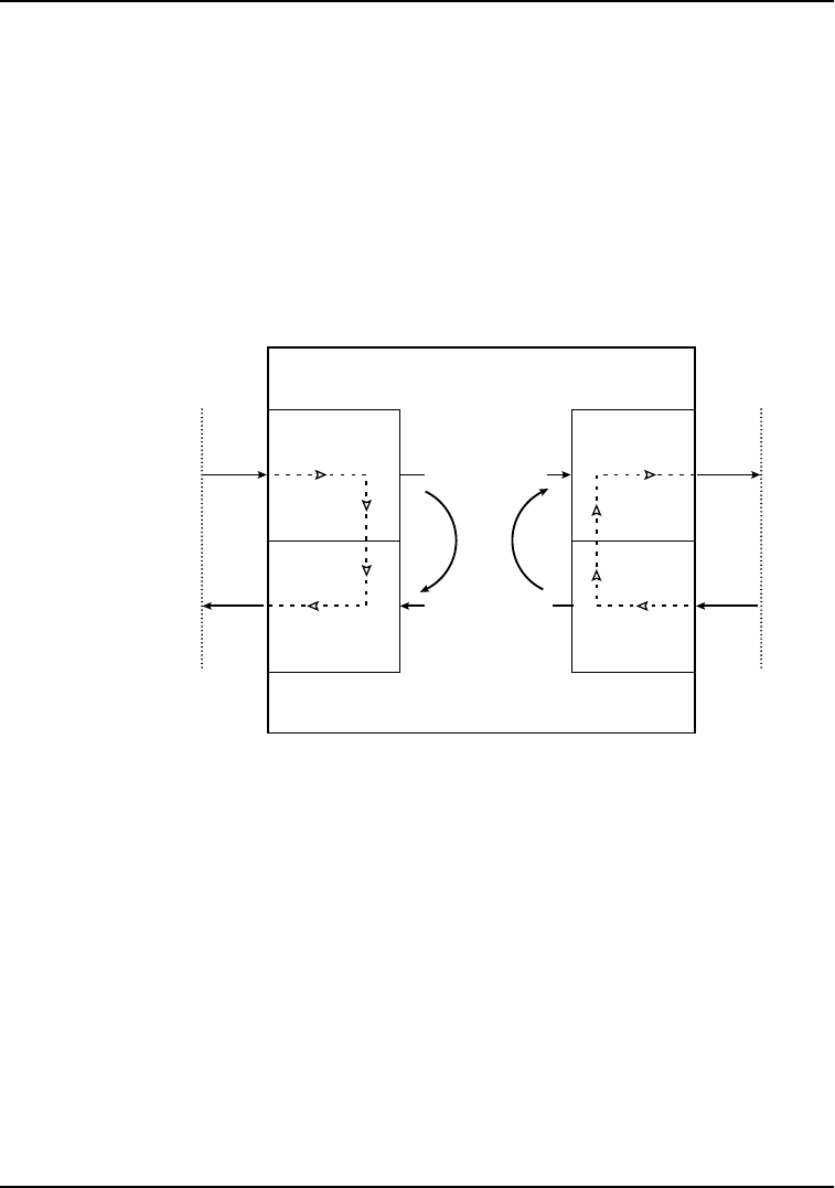
DTE AND LOOP TEST (LL)
This test is initiated at the local DSU 56/64 and allows independent
testing of the separate sections of the DSU 56/64. This includes
testing of the local DTE interface with data from the terminal or test
equipment and testing of the loop interface section of the local DSU
56/64 DSU
DTE
Receive
Interface
DTE
Transmit
Interface
Test
Pattern
Generator
Test
Pattern
Detector
Loop
Transmit
Interface
Loop
Receive
Interface
DTE
with
Test Pattern
TD
DTE or Test
Equipment
Interface
Network
Interface
RD
Loop TX
Loop RX
Chapter 3. Test Modes
61200062L1-1 DSU 56/64 User Manual 3-5
56/64 from the remote site over the actual communications circuit.
Testing from the remote end of the circuit is performed with test
data generated by the remote DSU or terminal type test equipment.
The DTE AND LOOP test splits the DSU 56/64 into separate DTE and
Loop interface sections and then loops the transmit data of each
interface back to its respective receive data. Figure 3-3 illustrates
the loopback points and the signal paths for this test. The DTE AND
LOOP LEDs flash during initialization of the test and turn on solid
once the test is in progress.
Figure 3-3. DTE and Loop Test Diagram
To initiate the DTE AND LOOP test, perform the following steps:
1. Press SELECT three times to turn on both the DTE AND LOOP
test indicators.
2. Press TEST while these test indicators are on.
3. To terminate this test, press TEST.
56/64 DSU
DTE
Receive
Interface
DTE
Transmit
Interface
Loop
Transmit
Interface
Loop
Receive
Interface
DTE
and
Loop
TD
DTE or Test
Equipment
Interface
Network
Interface
RD
Loop TX
Loop RX
Chapter 3. Test Modes
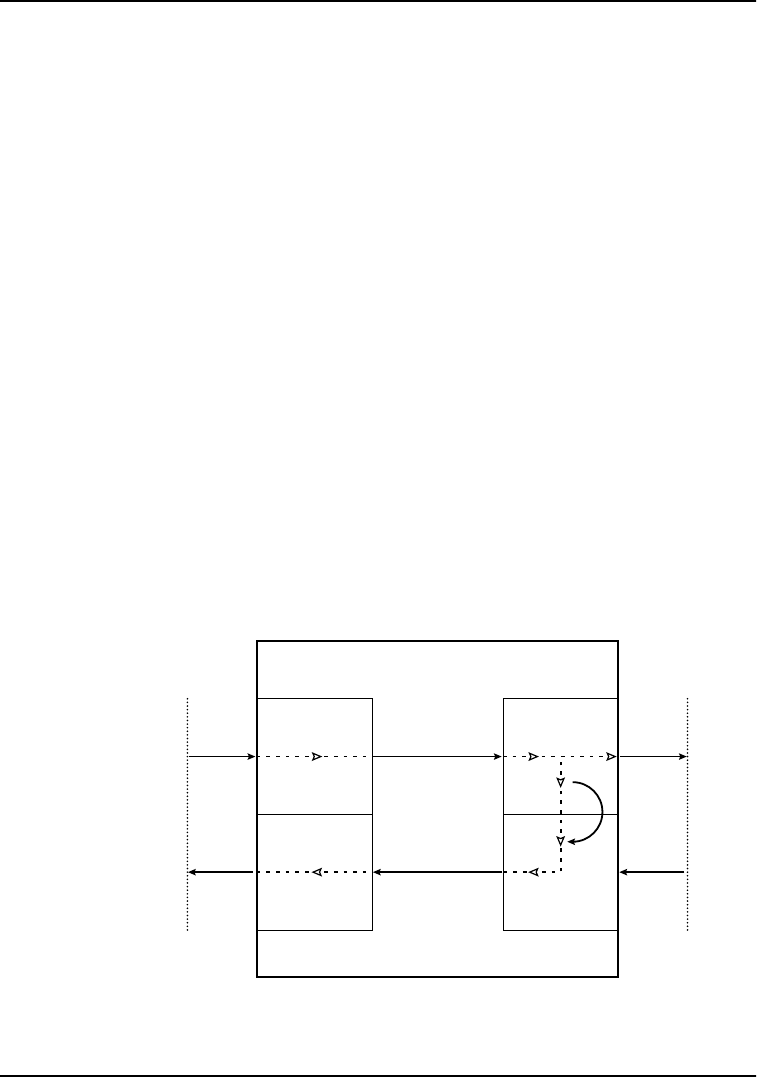
3-6 DSU 56/64 User Manual 61200062L1-1
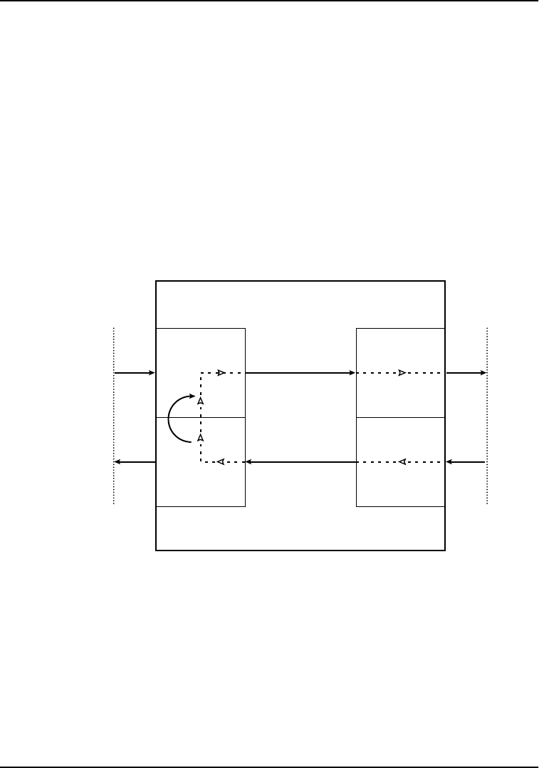
LOOP ONLY TEST (RT)
The LOOP ONLY test or REMOTE LOOPBACK test (RT) is used to test
the loop interface and a major portion of the DTE interface of the
local DSU 56/64 from the remote site over the actual digital data
circuit.
For the LOOP ONLY test, the network receive data is looped to the
network transmit data inside the DTE interface section of the DSU
56/64. The physical DTE interface is ignored for this test. The LOOP
LED flashes during initialization of the test and turns on solid once
the test is in progress. Figure 3-4 illustrates the loopback point and
the signal paths for this test.
Figure 3-4. Loop Only Test Diagram
To initiate the LOOP ONLY test, perform the following steps:
1. Press SELECT four times to turn on the LOOP test indicator.
2. Press TEST while this test indicator is on.
3. To terminate this test, press TEST.
56/64 DSU
DTE
Receive
Interface
DTE
Transmit
Interface
Loop
Transmit
Interface
Loop
Receive
Interface
Loop
Only
TD
DTE or Test
Equipment
Interface
Network
Interface
RD
Loop TX
Loop RX

Chapter 3. Test Modes
61200062L1-1 DSU 56/64 User Manual 3-7
FAR END TESTS
Remote Digital
When the RDL test is initiated at the local DSU 56/64, it commands
the remote DSU into loopback with the industry standard V.54
loopback pattern. The loopback point and the signal paths for the
remote DSU are the same as the LOOP ONLY test for a local DSU,
shown in Figure 3-4 on page 3-6. This Loopback test is performed
with data from the terminal or test equipment. The RDL LED
flashes during initialization of the test and turns on solid once the
test is in progress.
To initiate the RDL test, perform the following steps:
1. Press SELECT five times to turn on the RDL test indicator.
2. Press TEST while this test indicator is on.
3. To terminate this test, press TEST.
RDL with Test Pattern (TP)
When the RDL WITH TP test is initiated at the local DSU 56/64, the
local DSU commands the remote DSU into loopback with the
industry standard V.54 loopback pattern. The loopback point and
the signal paths for the remote DSU are the same as the LOOP ONLY
test for a local DSU; see Figure 3-4 on page 3-6. This LOOPBACK test
is performed with data from the internal test pattern generator and
error detector. The RDL and PTRN LEDs flash during initialization
of the test and turn on solid once the test is in progress.
To initiate the RDL WITH TP test, perform the following steps:
1. Press SELECT six times to turn on both the RDL and PTRN test
indicators.
2. Press TEST while these test indicators are on.
3. To terminate this test, press the TEST switch.

Chapter 3. Test Modes
3-8 DSU 56/64 User Manual 61200062L1-1
Test Pattern (PTRN)
When the PTRN test is initiated, the local DSU 56/64 uses the
integral test pattern generator to transmit a standard 2047 test
pattern to the DSU on the far end of the circuit. The local DSU 56/
64 then examines the received data for the standard 2047 pattern.
Once this pattern is detected and synchronization is achieved, the
ERROR indicator is turned off. The ERROR indicator turns on when
errors in the receive data pattern are detected. While this test is
active, errors can be injected into the transmit data stream by
pressing the SELECT push-button. The PTRN LED flashes during
initialization of the test and turns on solid once the test is in
progress.
To initiate the PTRN test, perform the following steps:
1. Press SELECT seven times to turn on the PTRN test indicator.
2. Press the TEST switch while this test indicator is on.
3. To terminate this test, press TEST.

Chapter 3. Test Modes
61200062L1-1 DSU 56/64 User Manual 3-9
REMOTE TESTS
The DSU 56/64 responds to three remotely activated tests.
• Remote Digital Loopback (RDL)
•CSU Loopback (LL)
• DSU Loopback (RT)
The RDL test is initiated by a remote DSU and causes the local DSU
56/64 to loopback. The loopback point is the same as the loop only
point. See Figure 3-4 on page 3-6. This test is run to test the end-to-
end performance of the circuit.
Both the CSU LOOPBACK and the DSU LOOPBACK tests are
activated from the telephone company diagnostic test equipment
and are used to isolate trouble on a circuit.
The CSU LOOPBACK, commonly called the LL test, has the same
loopback points as the DTE AND LOOP test. It is used by the
telephone company to test the integrity of the local loop.
The DSU LOOPBACK, commonly called the RT test, has the same
loopback point as the LOOP ONLY test and is used by the telephone
company to test the operation of both the local loop and DTE
interface sections.

Chapter 3. Test Modes
3-10 DSU 56/64 User Manual 61200062L1-1

61200062L1-1 DSU 56/64 User Manual A-1
Appendix A Pinouts
Table A-1. Pinouts for RJ-48S Network Connections
Pin Number Function Signal Direction
1 Transmit Data (R) From Customer to Network Interface
2 Transmit Data (T) From Customer to Network Interface
3-6 Not Used N/A
7 Receive Data (T-1) From Network Interface to Customer
8 Receive Data (R-1) From Network Interface to Customer

Appendix A. Pinouts
A-2 DSU 56/64 User Manual 61200062L1-1
Table A-2. V.35 DTE Pinouts
Pin CCITT Description
A 101 Protective Ground
B 102 Signal Ground (SG)
C 105 Request to Send (RS)
D 106 Clear to Send
E 107 Data Set Ready (SR)
F 109 Receive Line Signal Detector (CD)
R 104 Received Data (RD-A)
T 104 Received Data (RD-B)
V 115 Receiver Signal element Timing (SCR-A)
X 115 Receiver Signal Element Timing (SCR-B)
P 103 Transmitted Data (SD-A)
S 103 Transmitted Data (SD-B)
Y 114 Transmitter Signal element Timing (SCT-A)
AA 114 Transmitter Signal element Timing (SCT-B)
U 113 External TX Signal element Timing (SCX-A)
W 113 External TX Signal element Timing (SCX-B)

61200062L1-1 DSU 56/64 User Manual B-1
Appendix B Specifications
SPECIFICATIONS AND FEATURES
The DSU 56/64 is a single stand-alone unit designed to be used
either on a desktop or mounted on a wall.
This section describes the standard specifications and features
incorporated in the DSU 56/64.
Loop Interface
• 4-wire, full duplex
Line Requirements
• Local loop specifications per AT&T Pub 62310
Loop Rates
• 56 kbps or 64 kbps
Receiver Sensitivity
•-45 dB
DTE Interfaces
• V.35 synchronous
DTE Operating Modes
• Full or half duplex
DTE Data Rates
• 56 kbps or 64 kbps synchronous

Appendix B. Specifications
B-2 DSU 56/64 User Manual 61200062L1-1
Diagnostics
Network test center activated:
• CSU loopback on sealing current reversal in local loop
• DSU loopback
User activated:
• Self test,
• Local loopback,
• V.54 activated remote loopback with 2047 test pattern
• DTE data/data from external test set
Power
•115 VAC
• 4 Watts (maximum)
Environment
• Operating Temperature: 0o C to 50o C (32o F to 122o F
• Storage Temperature: - 20o C to 70o C (-4o F to 158o F)
• Relative Humidity: Up to 95%, non-condensing
Hardware Specifications
• Dimensions: 1.56 inches H, 6.50 inches W, 8.32 inches L
•Weight: 1.5 pounds

61202062L1-1 DSU 56/64 User Manual Index-1
Index
A
ACES help desk, xi
affidavit
connection for digital services, iv
connection of CPE equipment, v
antistream - SW-1, 2-3
Applications engineering
how to contact, xi
C
cables
included with shipment, 2-1
provided by customer, 2-1
Canadian emissions requirements, viii
Canadian equipment limitations, ix
CAPS department
how to contact, xi
carrier detect (CD) - SE-4, 2-3
clear to send (CS) SW-1, 2-2
clear to send delay (CS delay) - SW-2, 2-2
configuration
for network and DTE interfaces, 2-2
customer service, xi
D
data set ready (SR) - SW-5, 2-3
diagnostics, of DSU 56/64, B-2
DTE and Looptest 3-4
DTE connections, 2-5
DTE status
LED identification, 1-2
DTE with TP test 3-3
DTE-only test 3-2
E
environmental specifications, B-2
F
Far End Tests 3-7
FCC radio frequency interference, viii
FCC regulations, vii
features of DSU 56/64, B-1
front panel
description and drawing, 1-2
LED identification, 1-2
test switches, 1-3
H
help desk
how to contact, xi
L
LED identification
DTE status 1-2
for front panel, 1-2
Network Status, 1-2
test status/error 1-3
Loop Only Test 3-6
loop rate - SW-7, 2-4
N
network connections, 2-5
Network status
LED identification, 1-2
P
pinouts
RJ-48S network connections, A-1
V.35 DTE, A-2
power cord
description of, 2-2
power features, B-2
product overview, 1-1
product warranty, x
PTRN test 3-8
R
rear panel
description and graphic, 1-4
remote digital loopback (RDL) - SW-6, 2-4
remote digital test 3-7

Index
Index-2 DSU 56/64 User Manual 61202062L1-1
remote tests 3-9
repair and return information, xi
RJ-48S network connections,
pinouts, A-1
RMA requests xi
S
safety instructions, iii
scrambler - SW-8, 2-4
self-test mode 3-1
service type information vii
shipping damage
what to do 2-1
shipping package
contents of, 2-1
specifications B-1
T
technical support
how to contact, xi
test modes 3-1
DTE and Loop Test, 3-4
DTE with Test pattern test, 3-3
DTE-only test, 3-2
Far End Tests, 3-7
loop only test, 3-6
PTRN test, 3-8
remote digital, 3-7
remote tests, 3-9
self-test 3-1
test status/error
LED identification, 1-3
test switches
on front panel 1-3
training information
how to contact, xii
V
V.35 DTE pinouts, A-2
W
warranty, x
