Adtran Recording Equipment 850 Users Manual
850 to the manual 5039f27d-e533-424d-bfc8-ba997e190413
2015-01-24
: Adtran Adtran-Recording-Equipment-850-Users-Manual-345282 adtran-recording-equipment-850-users-manual-345282 adtran pdf
Open the PDF directly: View PDF ![]() .
.
Page Count: 10
61200376L1-5B
Issue 2, June 2000
CLEI Code: SILCHL0DAA
TA 850 System Installation and Maintenance
61200376L1-5B 1
Trademarks: Any brand names and product names included in this document are
trademarks, registered trademarks, or trade names of their respective holdres.
Contents
1. General...........................................................................1
2. Product Overview........................................................ 1
3. Installation.....................................................................2
4. Specifications................................................................. 6
5. Maintenance.................................................................. 6
6. Warranty and Customer Service................................ 6
7. Limited Product Warranty.......................................... 7
8. Regulatory Requirements............................................ 7
Figures
Figure 1. TA 850................................................................ 1
Figure 2. TA 850 Backplane............................................. 2
Figure 3. TA850 Component Layout and Cable Con-
nections.............................................................. 3
Figure 4. Connector Pinout............................................. 5
Figure 5. T1 Connections................................................. 5
Figure 6. Alternate Power Connection..........................5
Figure 7. Office Alarm Connections..............................6
Tables
Table 1. TA 850Backplane Connections....................... 4
Table 2. Wire Wrap Identification..................................6
Table 3. Alarm Notification............................................. 6
Table 4. Specifications and Part Numbers.................. 10
1. GENERAL
This practice provides installation and maintenance
procedures for the ADTRAN Total Access 850 (TA 850)
System. The Specifications and Part Numbers Table
(Table 4onpage 10)showspartnumbersforequipment
and documents referenced in this practice. Referenced
practices should be on-hand during system installation.
Revision History
This is the initial release of this document. Future revi-
sions to this document will be described in this subsec-
tion.
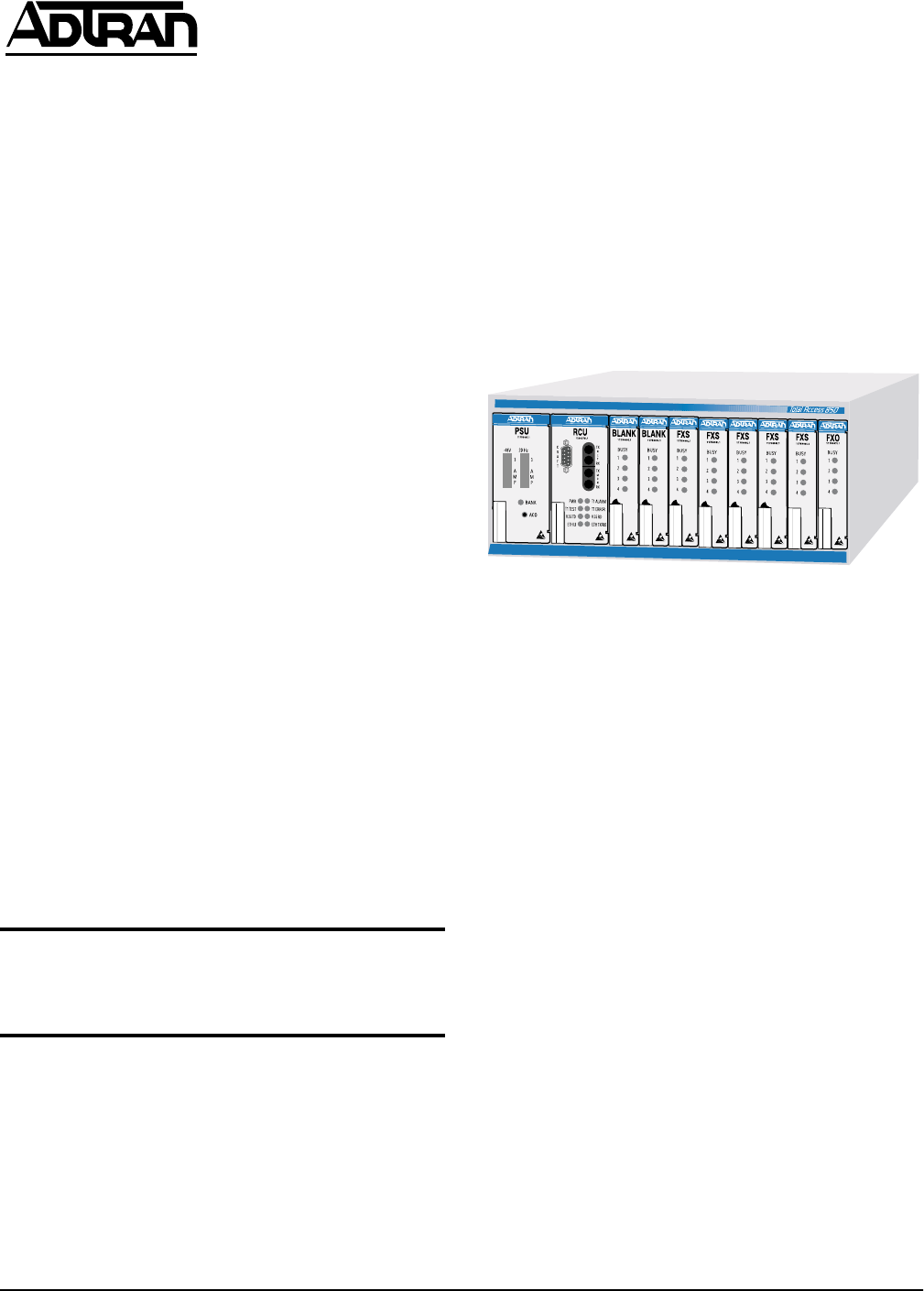
2. PRODUCT OVERVIEW
TheTA850system(seeFigure1)is anintegrated access
device designed for cost-effective deployment of voice
and data services at the customer’s premises. The
TA 850 system benefits integrated communications
providers,suchasCLECs,ILECs,andISPs,whorequire
a customer premises device that integrates voice and
data functions, and provides a viable migration path
from TDM to packet-based technology. The TA 850
features remote management, an integrated IP/IPX
router, and special services slots.
Figure 1. TA 850
TheTA850isamodulardevice,withtwocommonslots
and eight access slots. Common cards required for op-
eration are a power supply unit (PSU) and a router con-
trol unit (RCU). The RCU is a card that currently
supportsTDM-basedapplications,butcan be easily up-
graded to an ATM-based controller as requirements
change. The RCU includes a T1 network interface,
DSX-1PBXinterface,Nx56/64V.35interface,andbuilt-
in IP/IPX router. Six access slots allow the user to com-
bineavarietyofvoiceanddataservices.UptosixQuad
FXS or Quad FXO access modules can be installed to
support up to 24 analog voice lines. Other access mod-
ules for data applications include the OCU DP and
ISDN U-BR1TE. The other two access slots are for fu-
ture hardware options.
Usinglocalorremoteinband management,carrierscan
turn features, functions, and access ports on and off.
Easy access to modules, common cards, power sup-
plies, and the battery back-up system simplify mainte-
nance procedures. Hot-swappable modules may be
replaced without disrupting other units. The four-cir-
cuit-per-module design ensures that only four analog
circuits are affected when replacing a module.
A compact, NEBS-compliant cabinet suitable for the
customer premises or the central office provides added
safety and reliability. The 2U design uses little rack
space. When wall mounted, the 8.5-inch by 11-inch
NOTE
This is not an operational manual. To obtain an
operational manual, contact ADTRAN Technical
Support at (888) 4ADTRAN.

2 Issue 2, June 2000 61200376L1-5B
chassis occupies a space the size of a piece of notebook
paper. Two TA 850 systems can be mounted side-by-
side in either 19-inch or 23-inch relay racks.
Preconfigured packages are available.
Features
TheTA850includesthefollowingfeatures:
• T1/FT1 integrated access
•TDMtoATMmigration
• Modular network interface for future xDSL compati-
bility
• Integrated IP/IPX router
• Integrated DSX-1 PBX interface
• V.35 Nx56/64 DTE interface
• TR-08 signaling support
• Analog FXS and FXO voice expansion (four per
board)
• SNMP management
• NEBS and UL 1950 compliance
• Industry leading 10-year warranty
Functional Description
The TA 850 System comprises the chassis, common
cards, and access modules. Associated with the system
are additional elements including an AC to DC power
supplyandbatterychargingunitandabatterypackfor
backup power.
External AC and DC Power. The ADTRAN AC/DC
Power Supply/Battery Charging unit receives its pow-
er from a standard 115 VAC outlet. During operation,
the power supply maintains -54 VDC to the PSU. The
power supply battery charging circuit maintains the
battery pack at peak charge. In the event of an AC pow-
er failure, the battery backup circuit automatically pro-
vides battery power to the PSU for up to 8 hours. When
AC power is restored, input power automatically re-
turns to the AC supply and the battery charging circuit
will recharge the battery to peak.
OntheTA 850chassis,theincomingpower termination
point is on either of two backplane connections: P7 or
P6. (See Figure 2.) Both sources connect directly to the
PSU.ConnectorP6isusedwhenthechassisispowered
by the ADTRAN AC/DC Power Supply unit (P/N
1175043L1) which mounts externally to the chassis.
Connector P7 is used when -48 VDC is available on site
and screw-type terminal connections are required.
Figure 2. TA 850 Backplane
PSU. The Power Supply Unit supplies -48 VDC and
20 Hz ringing voltage to the Router Controller Unit
(RCU) and the access modules. The PSU converts
-48 VDC input to the required voltages needed to oper-
ate all common units and access modules. The ring gen-
erator circuit provides 20 Hz ring voltage to the analog
access modules.
ThePSUfaceplate(seeFigure1onpage1)showsthe
following: two GMT fuses (one for power and one for
20 Hz ring voltage), a channel bank status LED, and an
alarm cutoff (ACO) pushbutton switch. The separately
fusedringgeneratorsuppliesupto20RENtotheaccess
modules.
RCU. TheRouterController Unit isadualboardassem-
bly that provides the network interface. The RCU can
provision, test, and provide status for any card in the
channelbank.Thefaceplatehasa DB-9CRAFT portcon-
nection, dual bantam jack connection, plus network,
V.35, and Ethernet LEDs.
Access Modules. The TA 850 is designed to support
Quad FXS, Quad FXO,OCU DP, and UBR1TE access
modules.
3. INSTALLATION
Before installing the TA 850, carefully inspect the
TA 850 Base Unit for shipping damage. If you suspect
damage, file a claim immediately with the carrier and
then contact ADTRAN Customer and Product Service.
( See “Warranty and Customer Service” on page 6.) If
possible, keep the original shipping container for re-
turning the TA 850 for repair or for verification of dam-
age during shipment.
Your ADTRAN shipment includes the following items
(if the unit is not purchased directly from ADTRAN, it
may be packaged differently):
• TA 850 chassis,PSU, RCU, and blanks
• TA 850 System Installation and Maintenance Practice
WARNING
On TA 850 installations that do not use all chassis
slots, UL 1950/NEBS requires that the empty slots
must have a TA 850 blank unit (part number
1175099L1) installed in the opening.
P7
P6

61200376L1-5B Issue 2, June 2000 3
Grounding Instructions
This section provides grounding instruction informa-
tion from the Underwriters' Laboratory UL 1950 Stan-
dard for Safety: Information Technology Equipment.
An equipment grounding conductor thatis not smaller
in size than the ungrounded branch-circuit supply con-
ductorsistobeinstalledaspartofthecircuitthatsup-
plies the productorsystem. Bare, covered,or insulated
grounding conductors are acceptable. Individually
covered or insulated equipment grounding conductors
shall have a continuous outer finish that is either green,
or green with one or more yellow stripes. The equip-
mentgroundingconductoristobeconnectedtoground
at the service equipment.
The attachment-plug receptacles in the vicinity of the
product or system are all to be of a grounding type, and
the equipment grounding conductors serving these re-
ceptacles are to be connected to earth ground at the ser-
vice equipment.
A supplementary equipment grounding conductor
shall be installed between the product or system and
ground that is in addition to the equipment grounding
conductor in the power supply cord.
The supplementary equipment grounding conductor
shall not be smaller in size than the ungrounded
branch-circuit supply conductors. The supplementary
equipment grounding conductor shall be connected to
the product at the terminal provided, and shall be con-
nected to ground in a manner that will retain the
ground connection when the product is unplugged
from the receptacle. The connection to ground of the
supplementary equipment grounding conductor shall
beincompliancewiththerulesforterminatingbonding
jumpers at Part K or Article 250 of the National Electri-
cal Code, ANSI/NFPA 70. Termination of the supple-
mentary equipment grounding conductor is permitted
to be made to building steel, to a metal electrical race-
way system, or to any grounded item that is perma-
nently and reliably connected to the electrical service
equipment ground.
Install the Chassis
Standard installation is a single unit wall mount. Posi-
tion the chassis with the access modules facing up.
Mount on heavy plywood (3/4 inch minimum). Refer
to Figure 3 for component layout.
Required Clearances. A minimum 10-inch clearance
is required on the front end for access module insertion
and withdrawal. Onthe backplane end, a five-inch
clearance is required for wiring access to the V.35 con-
nector. For those units installed in a communications
bay, standard bay clearances are satisfactory.
Figure 3. TA 850 Component Layout and Cable
Connections
Mounting Brackets. The TA 850 chassis includes wall
mount brackets. If rack mount brackets are needed,use
part number 1175045L1 or 1175046L1 for 19-inch or
23-inch, respectively.
Tools Needed (Wall-Mount). The TA 850 chassis
mountsandconnectswithstandardfastenersandhand
tools:
• Four #8 x 3/4 inch pan-head wood screws
• Drill and drill bit set
• Flat head screwdriver (medium)
• Two Phillips head screwdrivers (small /medium)
• Wire-wrap gun (optional)
• 5-pair male amphenol cable (customer connection)
• Selected punch-down block and tool
Mount the Chassis. Installthechassisasfollows:
1.Position the chassis at the desired location; observe
required clearances and ensure cable plugs reach
their designated sockets.
2.Ensure the chassis is plumb; then mark through the
flange mounting holes to identify where the pilot
holes will be drilled.
3.Using a 1/16 inch bit, drill pilot holes at the marked
locations.
4.Mount the chassis using the four #8 by 3/4 inch pan-
head wood screws.
Connections. Allconnectionsaremadethroughtermi-
nals, jacks, and wire-wraps on the backplane. Refer to
Figure 2 on page 2 for backplane connections. Refer to
Table 1 on page 4 for backplane reference designator
descriptions and functions supported.
A removable rear cover provides access to the back-
plane, andanaccesspanel that mountsto the rear cover
allows access to wire-wrap strips P1, P3, and P5, power
terminal strip P7, and clock termination switch SW1
without removingthe main rear cover. Most CPE appli-
cations will not require removal of the rear cover.
BATTERY
INPUT
ACALARM
OUTPUT
-54VDC
OUTPUT
120VAC/
2A60HZ INPUT
GROUND
+-
To Alarms
TA 850
AC/DC Power Supply
Battery Charging Unit
-48 VDC Backup Battery Pack
-54 VDC Output to TA 850
-54 VDC Battery
Charging/Discharging Line
AC Power Input
T1
DSX-1
V.35
CRAFT 10 BASE T
DC
POWER
WARNING:
20Hz FUSE
MUST BE REMOVED
BEFORE REAR COVER
D
J
N
T
X
BB
FF
LL
B
F
L
R
V
Z
DD
JJ
NN
C
H
M
S
W
AA
EE
KK
A
E
K
P
U
Y
CC
HH
MM
CAUTION
During TA 850 wall installation,
position chassis so front
panels face UP.

4 Issue 2, June 2000 61200376L1-5B
Table 1. TA 850 Backplane Connections
UL 1950 Deployment Guidelines. One of the follow-
ing two powering schemes shall be used when power-
ing this equipment:
1. Use the ADTRAN power supply (part number
1175043L1).
2. Do the following:
a.Connect the unit to areliablygrounded -48 Vdc
source which is electrically isolated from the AC
source.
b.A readily accessible disconnect device, suitably
approved and rated, shall be incorporated in the
input source wiring.
c.The branch circuit overcurrent protection shall be a
fuse or circuit breaker rated minimum 48 V, maxi-
mum 20 A.
d.This unit shall be installed in accordance with the
requirements of NEC NFPA 70.
The installation configurations codes are given below:
Alternate Connections. For wire-wrap or screw
terminalconnections,therearcoverdoesnotneedtobe
removed; only the terminal access cover needs to be
removed. Make wire-wrap or screw terminal
connections as follows:
1.Unscrew the access cover hold-down screw.
2.Slide the access cover down slightly to disengage the
lock-tabs from their slots.
3.Identify the wire-wrap pins designated for use, and
make the connections starting with the pins closest to
the exit port to avoid wiring interference as work
progresses.
4.If alternate power connection to P7 is to be used,
make those terminal connections last.
5.Carefully route wiring through the exit port.
6.Position and align the access cover tabs to the slots;
insert the tabs and slide the cover up slightly until
the screw holes are aligned. Ensure that exit wiring is
not pinched or damaged.
7.Reinsert the hold-down screw.
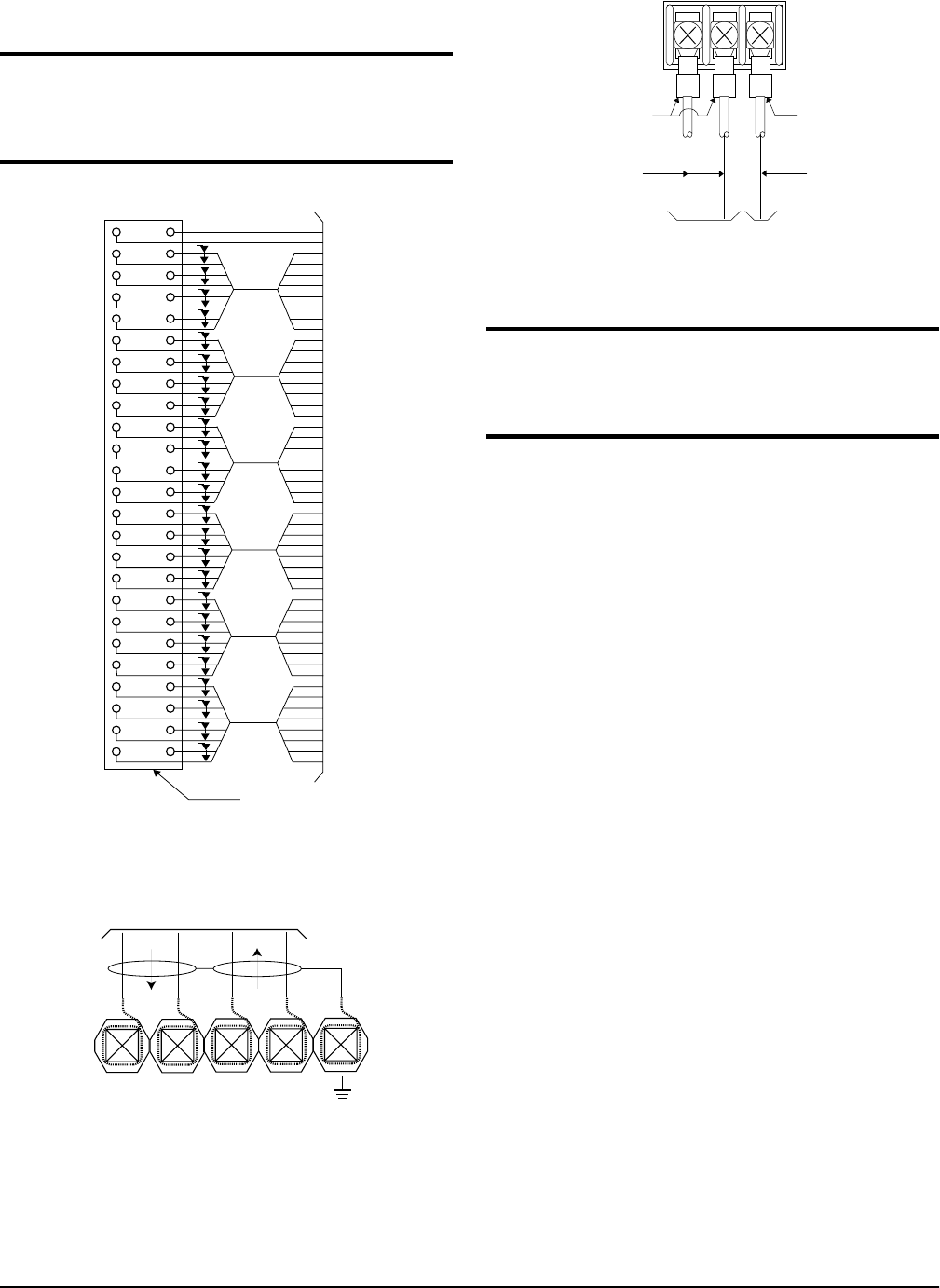
Customer Connection. One 50-pin male amphenol
connector (P2) provides the interconnect wiring for the
access modules located in slots 1 through 6 of the chas-
sis. This connector is usually terminated with a punch-
down block for premises wiring or connected directly
to a cross-connect or main distribution frame. Figure 4
on page 5 details the connector pinout.
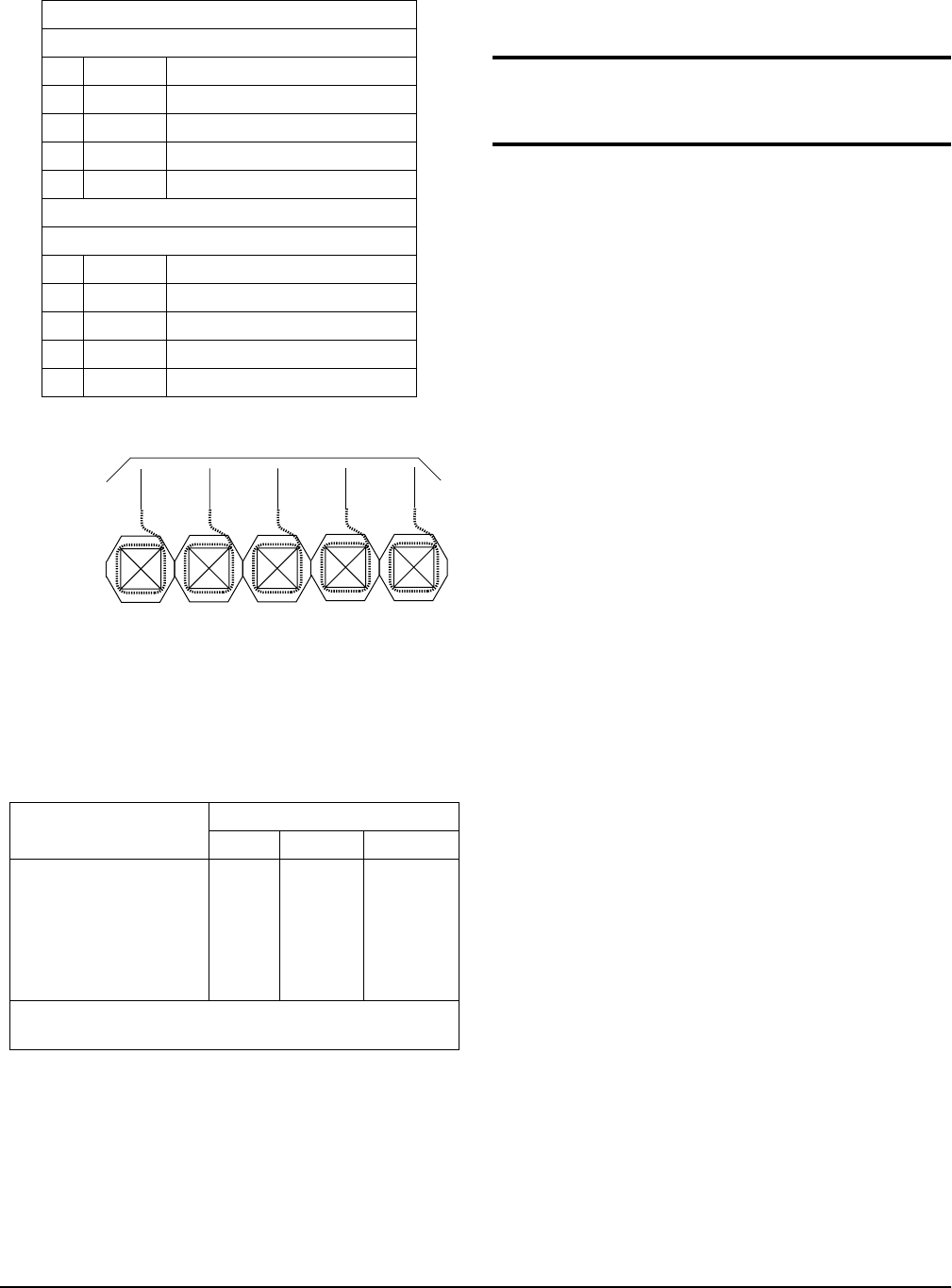
T1 Connection. Therearetwoterminationpointsfor
connecting the network T1 to the chassis: the primary
RJ-48 connector (JP2) and the alternate wire-wrap pins
on terminal strip P3 (as shown in Figure 2 on page 2).
Only one connector type is used(not both).
TheT1primaryconnectionisviatheRJ-48connectorlabeled
T1(JP2). ThisarrangementprovidesaconvenientT1connec-
tion for those installationswhere a T1 Smart Jackis used.
The RCU common module provides termination for
DSX-1andDS1signals.Forwire-wrapconnections,shield
is provided by the ground pin adjacent to the DSX-1/DS1
pin set (see Figure 5 on page 5). Line build-out and equal-
ization settings are provisioned on the RCU.
Power Connection. There are two power connec-
tions on the backplane: a modular DC plug (P6), and a
threelugterminalstrip(P7).(RefertoFigure2onpage2.)
The primary connection is the modular plug, which
receives -48 VDC from the ADTRAN power supply/
battery charging unit (P/N 1175043L1). The alternate
Ref Des Device/Label Technology
P1 wire-wrap strip clock/tests
P2 50 pin amphenol FXO, FXS, etc.
P3 wire-wrap strip alternate T1 interface
P5 wire-wrap strip alarms
P6 4 pin jack primary -48 V in
P7 3-lug terminal alternate -48 V in
JP1 RJ-48/E-NET 10BaseT Ethernet
JP2 RJ-48/T1 primary T1 interface
JP3 RJ-48/FT1 DSX1 interface
JP4 RJ-48/MAINT RS 232 craft interface
J1 V.35 Nx56K/64K
In Out
PC FC
IC E-
TC XX
CAUTION
Both Power and T1 services have two connection
points. In all cases, only one of the connection
points is used. Adhere to the instructions in the
following subsections to ensure correct installation.
CAUTION
Use wire gauge suitable for the application.
61200376L1-5B Issue 2, June 2000 5
connection is screw terminal P7, which canbe used if
-48 Vdc is available as in central office applications. The
screw terminal connection is shown in Figure 6 onpage 5.
Figure 4. Connector Pinout
Figure 5. T1 Connections
Figure 6. Alternate Power Connection
Office Alarms. Backplanealarmconnections(P5)are
labeled as shown in Table 2 on page 6 and illustrated in
Figure 7 on page 6. Alarm relay contacts are open dur-
ing normal operation. The alarm relay contacts close in
the event of a local alarm condition or the receipt of an
alarm from the T1 carrier. In a carrier alarm condition
suchasaRed,Yellow,orBlue(unframedall1s),various
alarm contacts in the PSU close. Carrier alarm condi-
tions cause the TA 850 to initiate trunk processing. The
following chain of events then occur:
1.MJ will be directly shorted to MJR.
2.MJV will be directly shorted to MJVR.
Contacts MJ and MJR can be overridden manually dur-
ing an alarm condition by pressing the ACO pushbut-
ton on the PSU faceplate. If the 3-Amp power fuse on
the PSU trips, the -48ALM relay will close, providing a
-48 VDC signal on that pin. This alarm cannot be over-
ridden by the ACO pushbutton. Refer to Table 3 on
page 6 for alarm notifications.
CAUTION
During installation, power should be the last
connection made after all other wire-wrap
connections are completed.
261
272
283
294
305
316
327
338
349
3510
3611
3712
3813
3914
4015
4116
4217
4318
4419
4520
4621
4722
4823
4924
5025
R
T
R
T
R
T
R
T
R
T
R
T
R
T
R
T
R
T
R
T
R
T
R
T
R
T
R
T
R
T
R
T
R
T
R
T
R
T
R
T
NC
P
P
P
P
P
P
P
P
P
P
P
P
P
P
P
P
P
P
P
P
50 PIN
AMP
RECEPTACLE
Slot 1
Slot 2
Slot 3
Slot 4
Slot5
R
T
T
R
T
T
R
R
Slot 6
P
P
P
P
Circuit 1
Circuit 2
Circuit 3
Circuit 4
Circuit 1
Circuit 2
Circuit 3
Circuit 4
Circuit 1
Circuit 2
Circuit 3
Circuit 4
Circuit 1
Circuit 2
Circuit 3
Circuit 4
Circuit 1
Circuit 2
Circuit 3
Circuit 4
Circuit 1
Circuit 2
Circuit 3
Circuit 4
R1
T1
R
T
To DSX-1/DS1
NOTE
The following section is for information only, and
the features described are not necessary for typical
applications.
20 AWG
RING LUG
20 AWG
SOLID
16 AWG
STRANDED
TO FUSE
PANEL TO WIRE WRAP
FRAME GROUND
16 AWG
RING LUG
BLK
FG
BLK
GRD
RED
-48V
6 Issue 2, June 2000 61200376L1-5B
Table 2. Wire Wrap Identification
Figure 7. Office Alarm Connections
Table 3. Alarm Notification
Install any Option Modules
After installing the TA 850 Base Unit and connecting
the required cables, you can install your choice of op-
tion modules.
Individual accessmodules insert fromthe front. A lock-
ing bar holds the modules in place for added security.
Disengaging the captured screw allows removal of the
locking bar. All wiring connections terminate on the
backplane. Refer to Table 2 on page 6 for wire-wrap
connections, and refer to Figure 2 on page 2 for back-
plane layout. Refer to Table 1 on page 4 for backplane
reference designator descriptions and functions sup-
ported.
Power-Up
As shipped, the T A850 is set to factory default condi-
tions. After installing the TA 850 Base Unit and any op-
tion modules, the TA 850 is ready for power-up.
4. SPECIFICATIONS
Table 4 on page 10 gives specifications and relevant
part numbers.
5. MAINTENANCE
The TA 850 System does not required programmed
maintenance for design operation.
ADTRANdoesnotrecommendthat repairsbe attempt-
edinthefield.Repairservicesareobtainedbyreturning
the defective unit to ADTRAN Customer Service.
6. WARRANTY AND CUSTOMER SERVICE
ADTRAN will replace or repair this product within ten
years from the date of shipment if the product does not
meet its published specifications or if it fails while in
service. For detailed warranty, repair, and return infor-
mationrefertotheADTRANEquipmentWarrantyand
Repair and Return Policy Procedure.
ReturnMaterial Authorization(RMA) is required prior
to returning equipment to ADTRAN.
Forservice,RMArequests,ormoreinformation,seethe
following sections for the correct toll-free contact num-
ber.
P3 Wire-Wrap Connections
T1 Connections
1 R1 DS1 Ring input from network
2 T1 DS1 Tip input from network
3 R DS1 Ring output from network
4 T DS1 Tip output from network
5 Gnd Ground
P5 Wire-Wrap Connections
Alarm Connections
1 -48 ALM DC Alarm output
2 MJVR Major Alarm Visual Common
3 MJV Major Alarm Visual
4 MJR Major Alarm Audible Common
5 MJ Major Alarm Audible
Alarm Condition Relays Activated
MJR MJVR -48 ALM
Red Alarm X X
Yellow Alarm X X
AIS Alarm X X
PSU Power Fuse Fails X X X
Alarms ACO Deactivates X X
Note: ACO will not deactivate MJR after a power fuse
failure.
MJVR
MJV
MJR
-48VALM
MJ
To customer designed remote alarms
WARNING
Remove the 20 Hz fuse before exposing backplane or
accessing channel units.

61200376L1-5B Issue 2, June 2000 7
Product Support Information
Pre-Sales Inquiries and Applications Support.
Please contact your local distributor, ADTRAN Appli-
cations Engineering, or ADTRAN Sales:
Post-Sale Support. Please contact your local distribu-
torfirst.Ifyourlocaldistributorcannothelp,please
contact ADTRAN Technical Support and have the unit
serial number available.
Repair and Return. If ADTRAN Technical Support
determines that a repair is needed, Technical Support
will coordinate with the Customer and Product Service
(CAPS)departmenttoissue anRMAnumber. Forinfor-
mation regarding equipment currently in house or pos-
sible fees associated with repair, contact CAPS directly
at the following number:
Identify the RMA number clearly on the package (be-
low address), and return to the following address:
ADTRAN, Inc.
6767 Old Madison Pike
Progress Center
Building #6 Suite 690
Huntsville, Alabama 35807
RMA # _____________
7. LIMITED PRODUCT WARRANTY
ADTRAN warrants that for ten years from the date of
shipment to Customer, all products manufactured by
ADTRAN will be free from defects inmaterials and
workmanship. ADTRAN also warrants that products
will conform to the applicable specifications and draw-
ings for such products, as contained in the Product
Manual or in ADTRAN's internal specifications and
drawings for such products (which may or may not be
reflected in the Product Manual). This warranty only
applies if Customer gives ADTRAN written notice of
defects during the warranty period. Upon such notice,
ADTRAN will, at its option, either repair or replace the
defective item. If ADTRAN is unable, in a reasonable
time, to repair or replace any equipmentto a condition as
warranted,Customerisentitledtoafullrefundofthepur-
chase price upon return of the equipment to ADTRAN.
This warranty applies only to the original purchaser and
is not transferable without ADTRAN's express written
permission. This warranty becomes null and void if Cus-
tomermodifiesoralterstheequipmentinanyway,other
than as specifically authorized by ADTRAN.
EXCEPTFORTHELIMITEDWARRANTYDESCRIBED
ABOVE,THE FOREGOING CONSTITUTESTHESOLE
AND EXCLUSIVE REMEDY OF THE CUSTOMER
AND THE EXCLUSIVE LIABILITY OF ADTRAN AND
IS IN LIEU OF ANY AND ALL OTHER WARRANTIES
(EXPRESSEDOR IMPLIED). ADTRANSPECIFICALLY
DISCLAIMS ALL OTHER WARRANTIES, INCLUD-
ING (WITHOUT LIMITATION), ALL WARRANTIES
OF MERCHANTABILITY AND FITNESS FOR A PAR-
TICULAR PURPOSE. SOME STATES DO NOT AL-
LOW THE EXCLUSION OF IMPLIED WARRANTIES,
SO THIS EXCLUSIONMAY NOT APPLY TO CUS-
TOMER.
In no event will ADTRAN or its suppliers be liable to
Customer for any incidental, special, punitive, exem-
plary or consequential damages experienced by either
Customerorathirdparty(including,butnotlimitedto,
loss of data or information, loss of profits, or loss of
use).ADTRANisnotliablefordamagesforanycause
whatsoever (whether based in contract, tort, or other-
wise)inexcessoftheamountpaidfortheitem.Some
states do not allow the limitation or exclusion of liabili-
tyforincidentalorconsequentialdamages,sotheabove
limitation or exclusion may not apply to Customer.
8. REGULATORY REQUIREMENTS
Affidavit Requirements for Connection to Digital
Services
• An affidavit is required to be given to the telephone
company whenever digital terminal equipment with-
out encoded analog content and billing protection is
used to transmit digital signals containing encoded
analog content which are intended for eventual con-
version into voiceband analog signals and transmit-
ted on the network.
• The affidavit shall affirm that either no encoded ana-
logcontentorbillinginformationisbeingtransmitted
orthatthe outputofthedevicemeetsPart68encoded
analog content or billing protection specifications.
• End user/customer will be responsible for filing an
affidavit with the local exchange carrier when con-
necting unprotected customer premise equipment
(CPE) to 1.544 Mbps or subrate digital services.
• Untilsuchtimeassubratedigitalterminalequipment
is registered for voice applications, the affidavit re-
quirement for subrate services is waived.
Applications Engineering (800) 615-1176
Sales (800) 827-0807
Technical Support (888) 4ADTRAN
CAPS Department (256) 963-8722

8 Issue 2, June 2000 61200376L1-5B
Affidavit for Connection of Customer Premises
Equipment to 1.544 Mbps and/or Subrate Digital
Services
Fortheworktobeperformedinthecertifiedterritoryof
________________________(telco name)
State of ________________
County of ________________
I, _____________________________ (name),
__________________________________(business ad-
dress),
____________________ (telephone number) being duly
sworn, state:
Ihaveresponsibility fortheoperationandmaintenance
of the terminal equipment to be connected to 1.544
Mbpsand/or________subratedigitalservices.Theter-
minalequipmentto beconnectedcomplies withPart68
of the FCC rules except for the encoded analog content
andbilling protection specifications.Withrespect to en-
coded analog content and billing protection:
( ) I attest that all operations associated with the
establishment, maintenance, and adjustment of the
digital CPE with respect to analog content and
encoded billing protection information continu-
ously complies with Part 68 of the FCC Rules and
Regulations.
( ) The digital CPE does not transmit digital signals
containing encoded analog content or billing infor-
mation which is intended to be decoded within the
telecommunications network.
( ) The encodedanalog content and billing protection is
factory set and isnot under the controlof the customer.
I attest that the operator(s)/maintainer(s) of the digital
CPE responsible for the establishment, maintenance,
and adjustment of the encoded analog content and bill-
ing information has (have) been trained to perform
these functions by successfully having completed one
of the following (check appropriate blocks):
( ) A. A training course provided by the manufac-
turer/granteeoftheequipmentusedtoencode
analog signals; or
( ) B. A training course provided by the customer or
authorized representative, using training
materials and instructions provided by the
manufacturer/grantee of the equipment used
to encode analog signals; or
( ) C. An independent training course (e.g., trade
school or technical institution) recognized by
the manufacturer/grantee of the equipment
used to encode analog signals; or
( ) D. In lieu of the preceding training requirements,
theoperator(s)/maintainer(s)is(are)underthe
control of a supervisor trained in accordance
with _________ (circle one) above.
I agree to provide ______________________ (telco’s
name)withproperdocumentationtodemonstratecom-
pliance with the information as provided in the preced-
ing paragraph, if so requested.
_________________________________Signature
_________________________________Title
_________________________________ Date
Transcribed and sworn to before me
This ________ day of ________, ________
_________________________________
Notary Public
My commission expires:
_________________________________
FCC regulations require that the following
information be provided in this manual to the
customer:
1.This equipment complies with Part 68 of the FCC
rules.The required label is affixed to the bottom of
the chassis.
2.AnFCC-compliant telephone cordandmodular plug
is provided with this equipment. This equipment is
designed to be connected to the telephone network
or premises wiring using a compatible modular jack
which is Part 68-compliant. See Chapter 2, Installa-
tion, for details.
3.If your telephone equipment (TA 850) causes harm to
the telephone network, the telephone company may
discontinue your service temporarily. If possible,
they will notify you in advance. But if advance notice
isn’t practical, you will be notified as soon as possi-
ble. You will be advised of your right to file a com-
plaint with the FCC.
4.Your telephone company may make changes in its
facilities, equipment, operations, or procedures that
could affect the proper operation of your equipment.
If they do, you will be given advance notice to give
you an opportunity to maintain uninterrupted service.
5.If youexperience trouble withthis equipment(TA 850),
please contact ADTRAN at (256) 963-8000 for repair/
warranty information.The telephone company may
ask you to disconnect thisequipment fromthe network
until the problem has been corrected or until you are
sure the equipment is not malfunctioning.
6.This unit contains no user-serviceable parts.

61200376L1-5B Issue 2, June 2000 9
7.The following information may be required when
applying to your local telephone company for leased
line facilities.
For a T1 Port:
For an FT1 Port:
This equipment has been tested and found to comply
with the limits for a Class A digital device, pursuant to
Part 15 of the FCC Rules. These limits are designed to
provide reasonable protection against harmful interfer-
ence when the equipment is operated in a commercial
environment. This equipment generates, uses, and can
radiate radio frequency energy and, if not installedand
used in accordance with the instruction manual, may
cause harmful interference to radio frequencies. Opera-
tion of this equipment in a residential area is likely to
cause harmful interference in which case the user will
be required to correct the interference at his own ex-
pense.
Shielded cables must be used with this unit to ensure
compliance with Class A FCC limits.
Canadian Equipment Limitations
Before installing this equipment, users should ensure
that it is permissible to be connected to the facilities of
thelocaltelecommunicationscompany.Theequipment
must also be installed using an acceptable method of
connection. In some cases, the company's inside wiring
associatedwithasinglelineindividualservicemaybe
extended by means of a certified connector assembly
(telephone extension cord). The customer should be
aware that compliance with the above conditions may
not prevent degradation of service in some situations.
Repairs to certified equipment should be made by an
authorized Canadian maintenance facility designated
by the supplier. Any repairs or alterations made by the
user to this equipment, or equipment malfunctions,
may give the telecommunications company cause to re-
quest the user to disconnect the equipment.
Users should ensure for their own protection that the
electrical ground connections of the power utility, tele-
phone lines and internal metallic waterpipe system, if
present,areconnectedtogether.Thisprecautionmaybe
particularly important in rural areas.
Service Type REN/
SOC FIC USOC
1.544 Mbps - SF 6.0N 04DU9-BN RJ-48C
1.544 Mbps - SF and
B8ZS 6.0N 04DU9-DN RJ-48C
1.544 Mbps - ESF 6.0N 04DU9-1KN RJ-48C
1.544 Mbps - ESF
and B8ZS 6.0N 04DU9-1SN RJ-48C
ISDN 6.0N 04DU9-ISN RJ-48C
Service Type REN/
SOC FIC
1.544 Mbps - SF 6.0N 04DU9-BN
1.544 Mbps - SF and B8ZS 6.0N 04DU9-DN
1.544 Mbps - ESF 6.0N 04DU9-1KN
1.544 Mbps - ESF and B8ZS 6.0N 04DU9-1SN
ISDN 6.0N 04DU9-ISN
NOTE
When connecting FT1 port towards the network, a
suitable crossover cable is required.
WARNING
Change or modifications to this unit not expressly
approved by the party responsible for compliance
could void the user’s authority to operate the
equipment.
NOTE
The Industry Canada Certification label identifies
certified equipment. This certification means that
the equipment meets certain telecommunications
network protective, operational, and safety
requirements. The Department of Commerce does
not guarantee the equipment will operate to the
user's satisfaction.
CAUTION
Users should not attempt to make such connections
themselves, but should contact the appropriate
electric inspection authority, or an electrician, as
appropriate.

10 Issue 2, June 2000 61200376L1-5B
TheLoadNumber(LN)assignedtoeachterminalde-
vice denotes the percentage of the total load to be con-
nected to a telephone loop which is used by the device,
to prevent overloading. The termination on a loop may
consistofanycombinationofdevicessubjectonlytothe
equipment that the total of the LNs of all devices does
not exceed 100.
Theringerequivalencenumber(REN)assignedtoeach
terminal adapter is used to determine the total number
of devices that may be connected to each circuit. The
sum of the RENs from all devices in the circuit should
not exceed a total of 5.0.
Canadian Class A Products
This Class A digital apparatus complies with Canadian
ICES-003.
Cet appareil numérique de la classe A est conforme á la
norme NMB-003 du Canada.
Table 4. Specifications and Part Numbers
Environmental
Operating Temperature -40to70oC (-40 to 158 oF)
Storage Temperature -30to70oC (-22 to 158 oF)
Relative Humidity 95% maximum, noncondensing
Physical
Dimensions 8 3/4” W x 3 5/8” H x 11” D
Weight (fully loaded) 8 pounds
Weight (empty) 5 pounds
TA 850 Relevant Part Numbers
TA 850 Chassis 1200375L1
RCU 1200376L1, User Manual 61200376L1-1A
PSU 1175006L1
Quad FXS 1175408L1, User Manual 61175408L1-1A
Quad FXO 1175407L1, User Manual 61175407L1-1A
AC Power Supply/Battery Charger 1175043L1/L2
Backup Battery Pack 1175044L1/L2
Single Unit 19” Rack Mount Brackets 1175045L1
Single Unit 23” Rack Mount Brackets 1175046L1
System Configuration Part Numbers
TA 850 DC Chassis Bundle 4200376L1
TA 850 AC Chassis Bundle 4200376L1#AC
TA 850 DC Chassis Bundle + 12 FXS 4200376L2
TA 850 AC Chassis Bundle + 12 FXS 4200376L2#AC
TA 850 DC Chassis Bundle + 16 FXS 4200376L3
TA 850 AC Chassis Bundle + 16 FXS 4200376L3#AC
