ADTRAN TRC3202 Tracer 3202 5.8 GHz Mastmount RFC User Manual 61280012L1 1A
Adtran Tracer 3202 5.8 GHz Mastmount RFC 61280012L1 1A
UserManual.wiki
>
ADTRAN
>
TRC3202 User Manual
Users manual
Navigation menu
Upload a User Manual
Namespaces
Wiki Guide
HTML
PDF
Info
Views
User Manual
Discussion / Help
Navigation

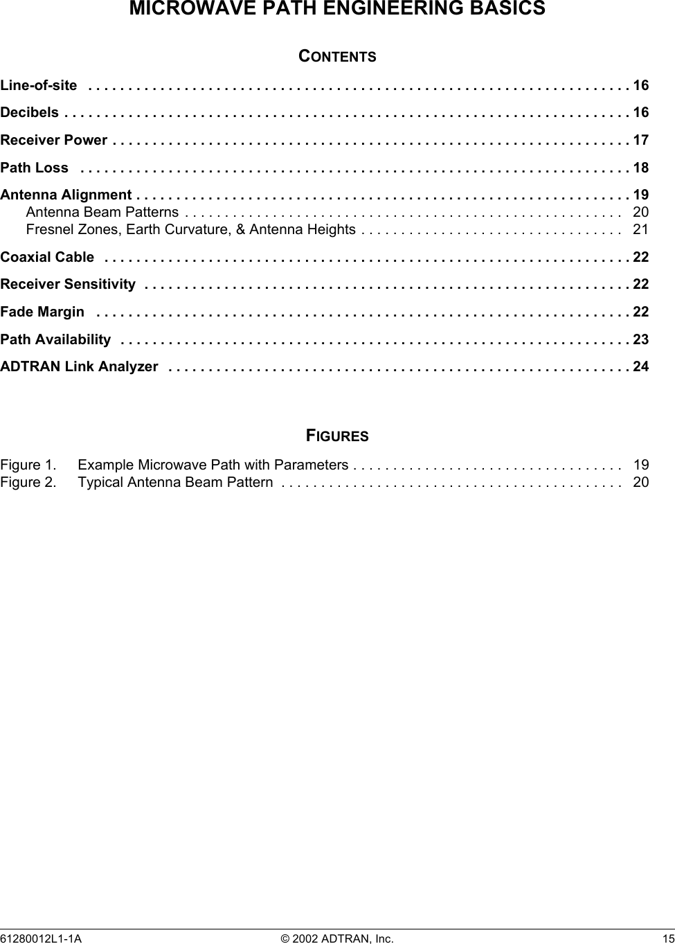
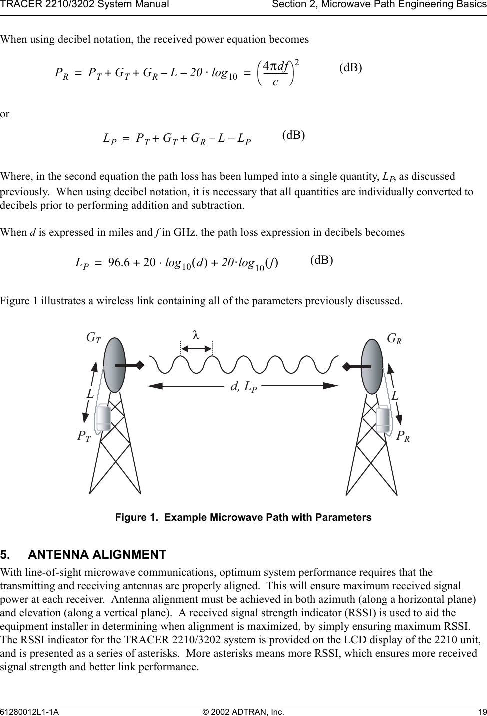
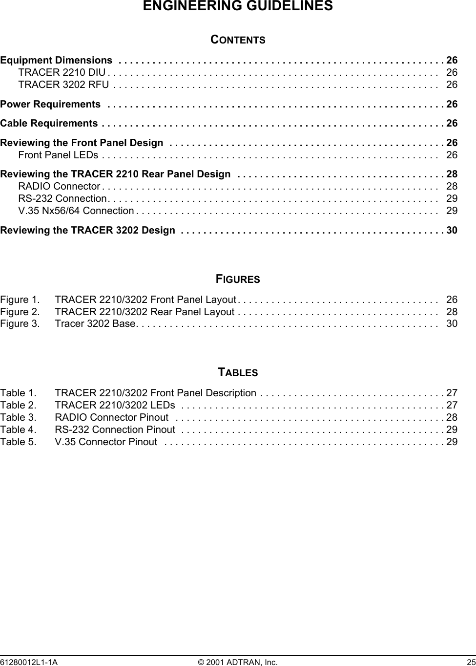
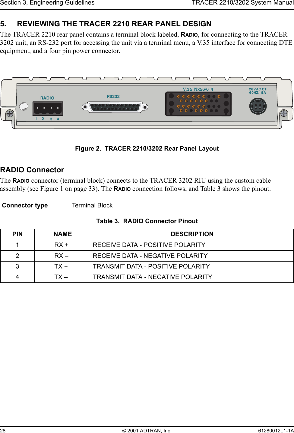
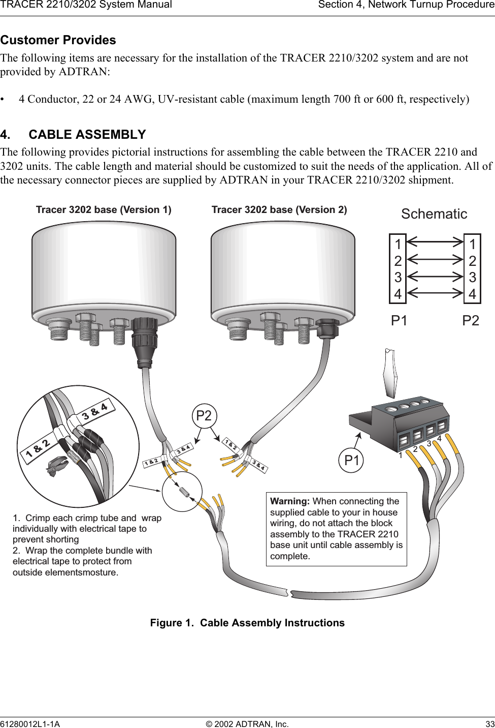
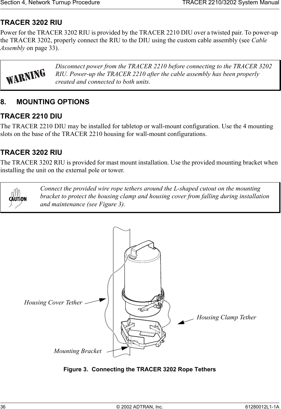
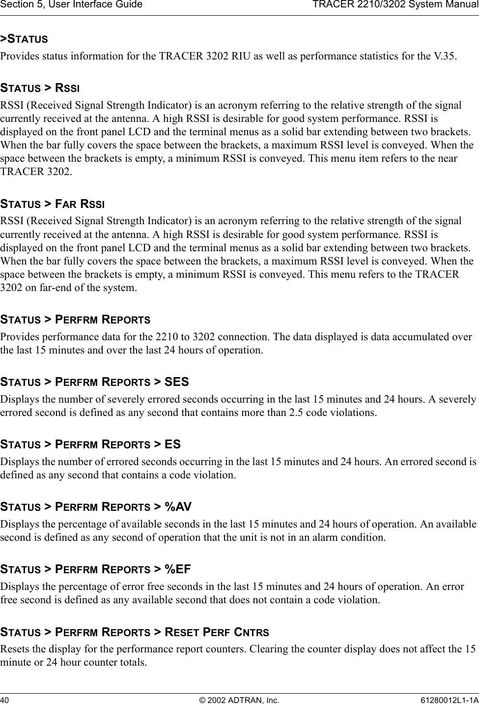
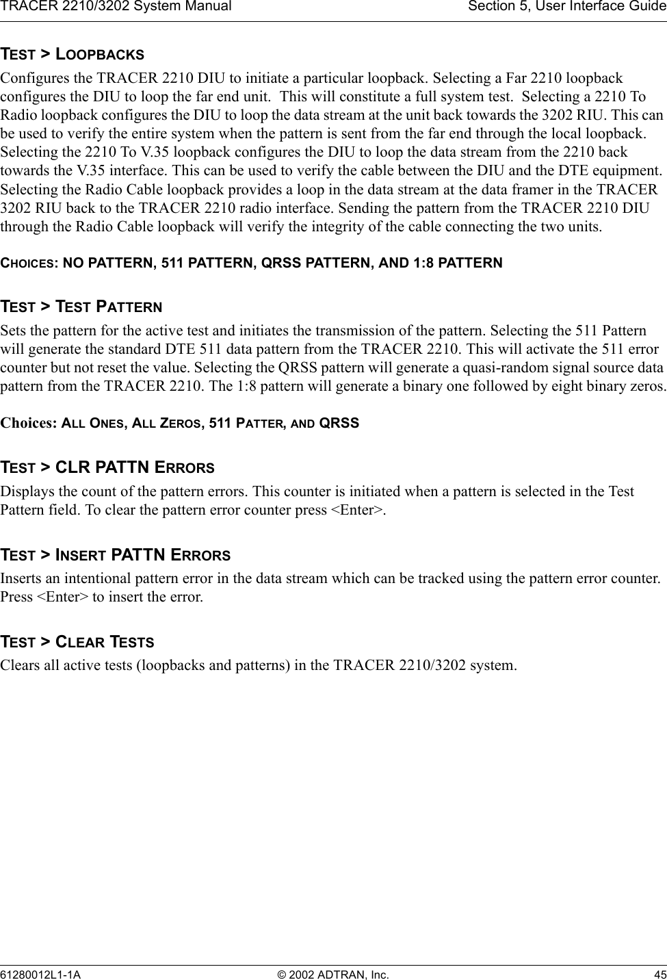
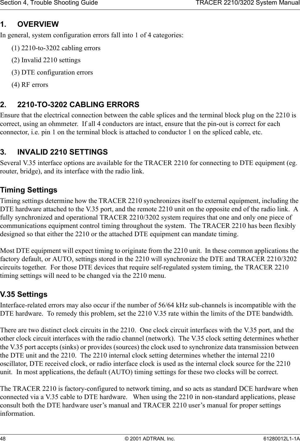
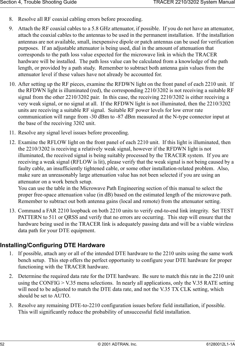
![Section 2, Microwave Path Engineering Basics TRACER 2210/3202 System Manual20 © 2002 ADTRAN, Inc. 61280012L1-1AUsing the 2210 keypad, look at the menu optionSTATUS ⇒ RADIO STATUS ⇒ RSSIto examine the RSSI value of the local TRACER 2210/3202 system. If the remote system has acquired a useful signal from the remote system, then the remote TRACER 2210/3202 RSSI can also be viewed from the local 2210 unit menu, via the keypad menu sequence:STATUS ⇒ FAR RADIO STATUS ⇒ RSSIAntenna Beam PatternsDirectly related to the subject of antenna alignment is the topic of antenna beam patterns. Antennas being used with the TRACER 2210/3202 system will have a particular beam shape determined in part by the physical construction and geometry of the antenna. The antenna beam patterns are characterized by a dominant main lobe, which is the preferred lobe to use for point-to-point communications, and several side lobes, as shown in Figure 2. The antenna alignment step to setting up a microwave link is in fact steering the main lobes of both antennas until the main lobe of one transmitter is centered on the receiving element of the receiving antenna.Figure 2. Typical Antenna Beam PatternAntennas are also designed to radiate RF energy efficiently for a specific range of frequencies. Please consult the data sheet for your particular antenna make and model to ensure that it is specified to operate in the 5725 MHz to 5850 MHz frequency band.RSSI[********* ____]FAR RSSI[********* ____]main lobeside lobes](https://usermanual.wiki/ADTRAN/TRC3202/User-Guide-239519-Page-20.png)
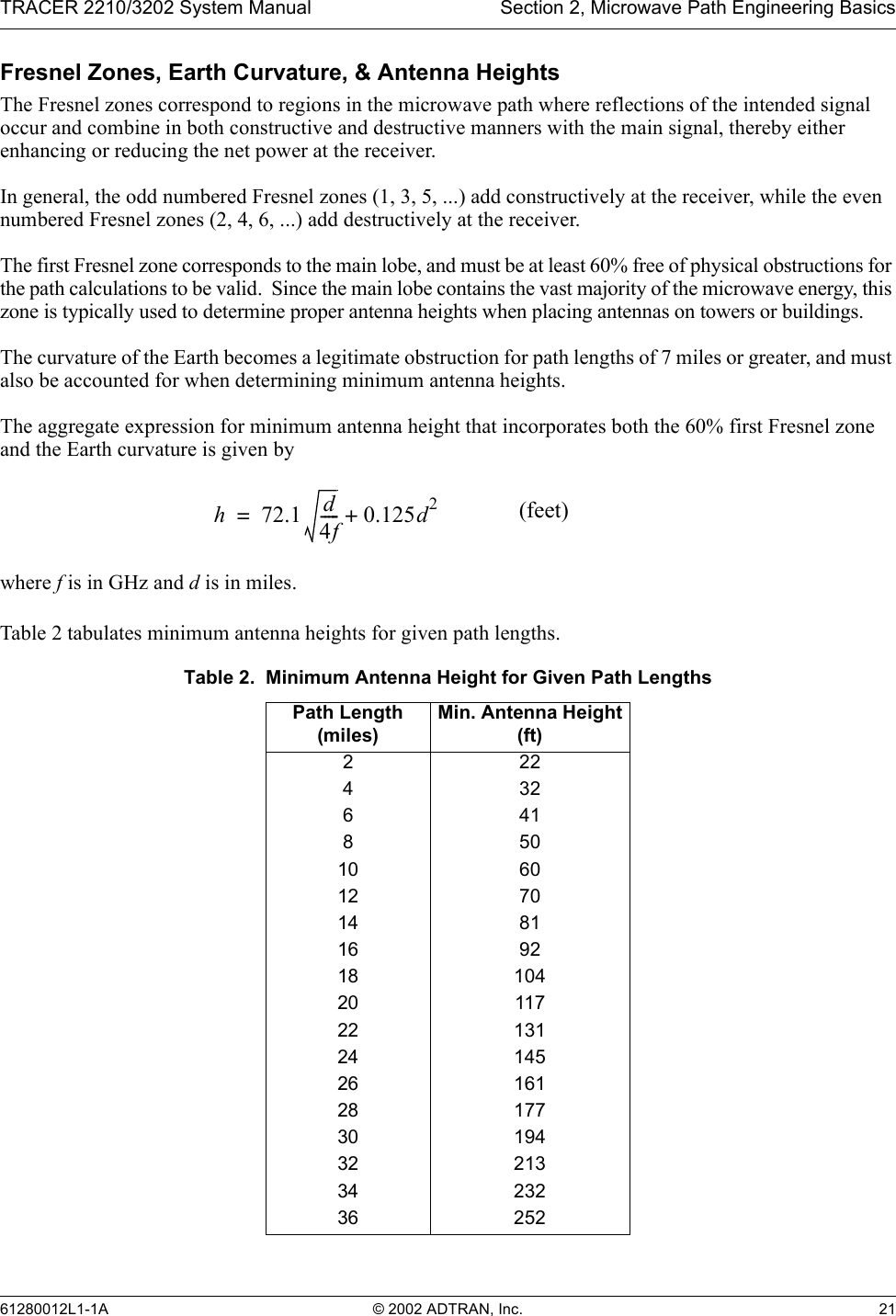
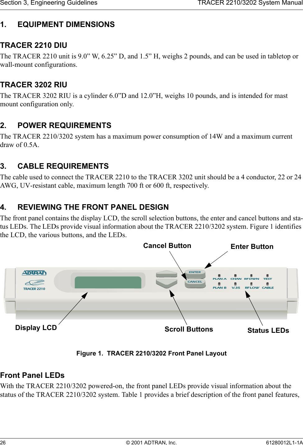
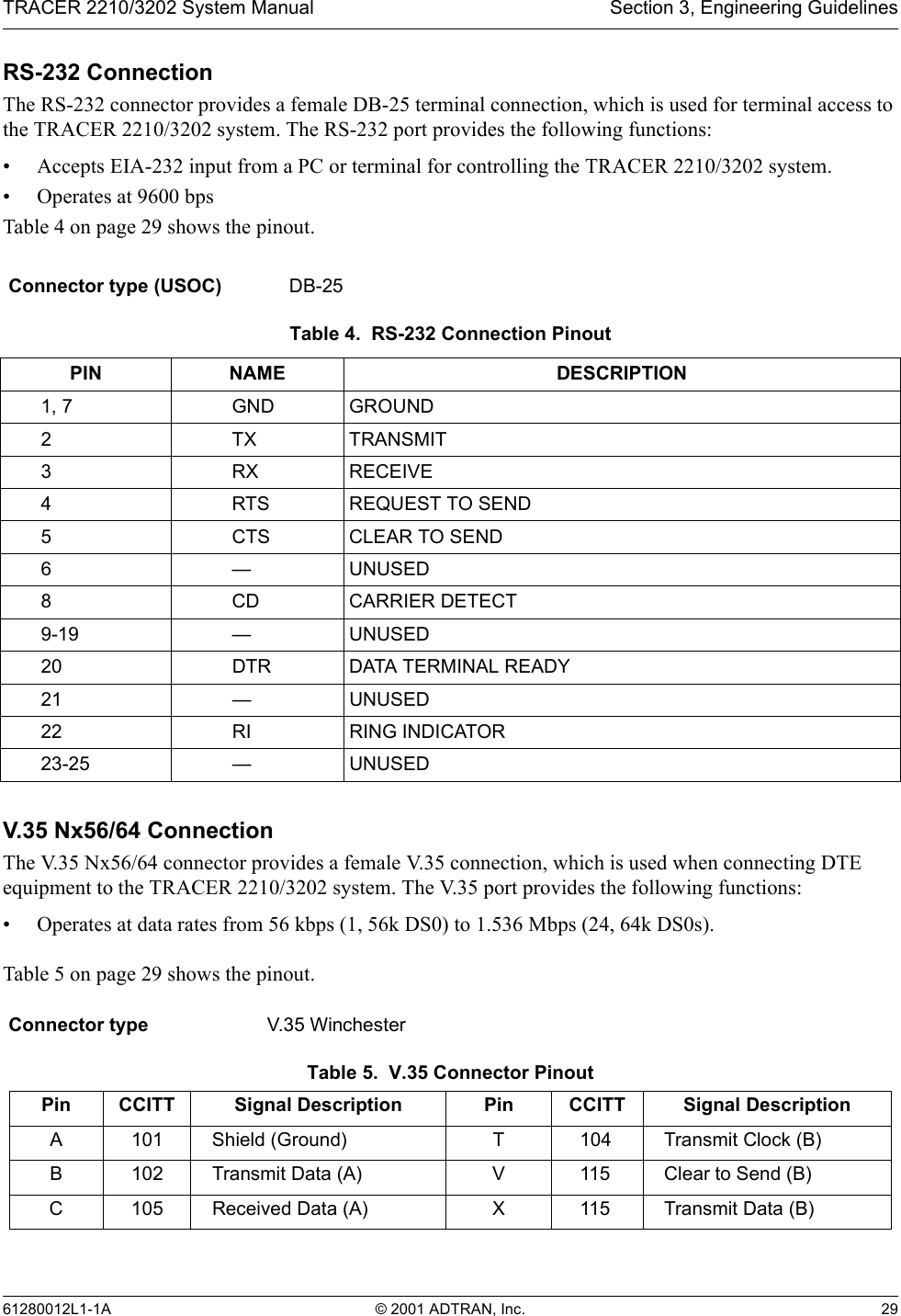
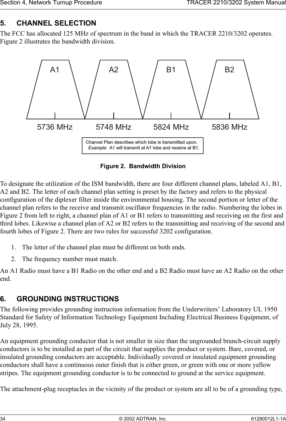
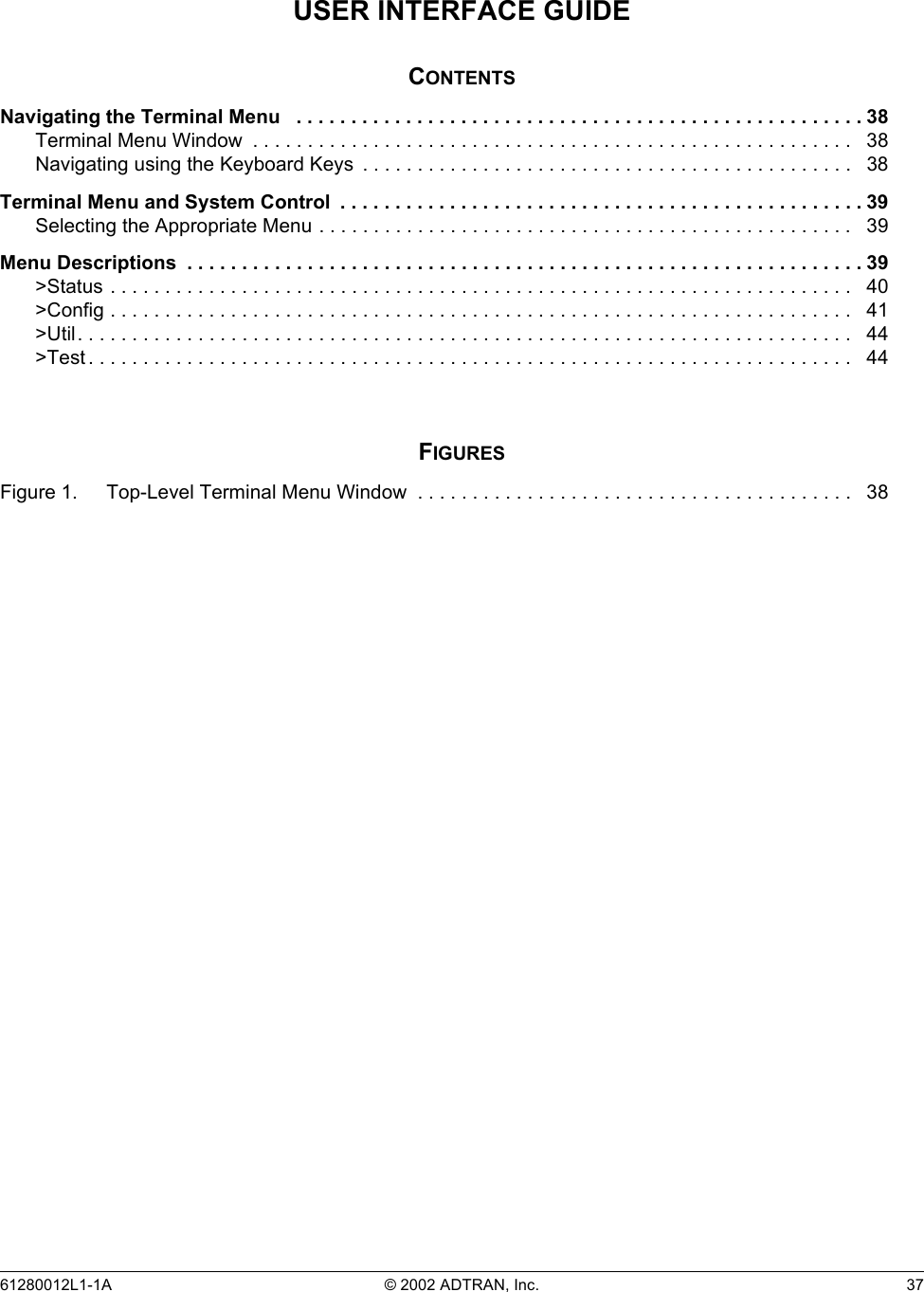
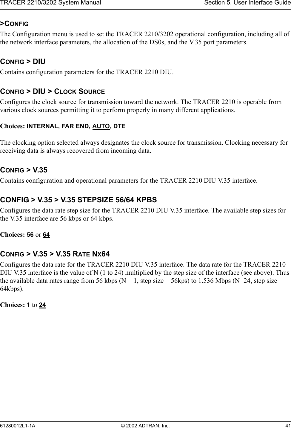
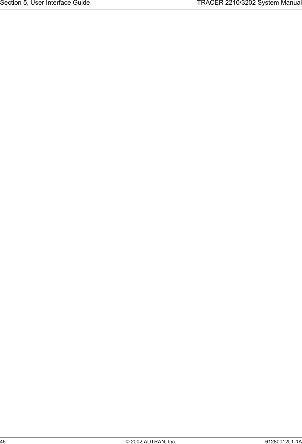
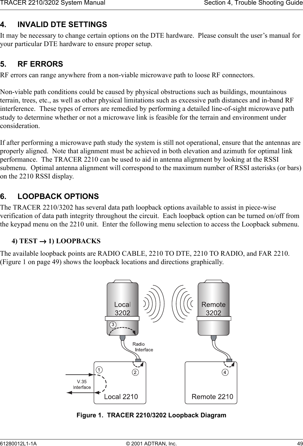
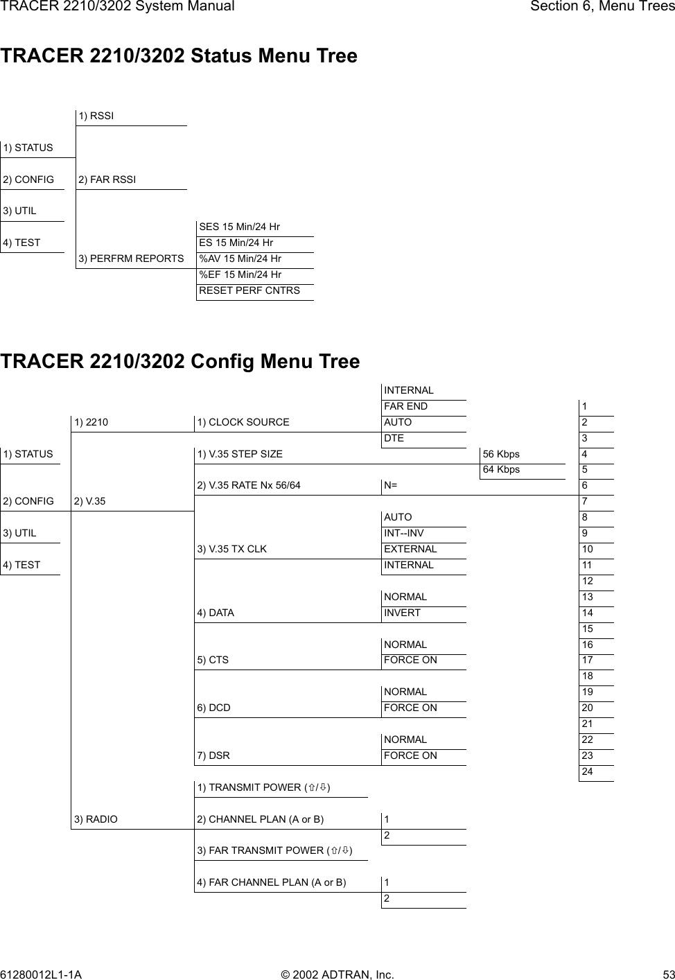
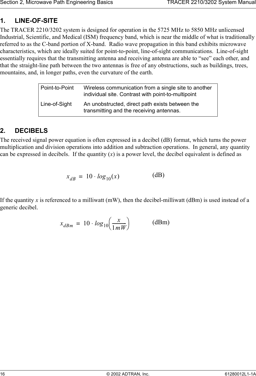
![TRACER 2210/3202 System Manual Section 2, Microwave Path Engineering Basics61280012L1-1A © 2002 ADTRAN, Inc. 239. PATH AVAILABILITYThe path availability of a wireless link is a metric that expresses the fractional amount of time a link is available over some fixed amount of time, and depends on several factors. Path availability is expressed aswhere the parameters areaterrain factorbclimate factorfcarrier frequency (GHz)dpath length (miles)Ffade margin (dB)The terrain factor is a quantity that compensates the link availability for different types of terrain. Generally speaking, the more smooth an area's terrain is, the less availability a wireless link running over that terrain will have, primarily due to multipath reflections. In contrast, secondary microwave signals will be randomly dispersed over rough terrain, and will not interfere with the main signal lobe as badly as in the smooth terrain case. The terrain factor values normally used are listed below:The climate factor is a quantity that compensates the link availability for different types of climates (weather). In general, microwave links operating in areas with high humidity will have less availability than those in arid areas, primarily because water is a dispersive mechanism to microwave energy, and causes the main signal lobe to refract and disperse away from the receiver location. The climate factor values normally used are listed below.Terrain Terrain Factor DescriptionSmooth 4 water, flat desertAverage 1 moderate roughnessMountainous 1/4 very rough, mountainousClimate Climate Factor DescriptionVery Dry 1/8 desert regionsTemperate 1/4 mainland, interior regionHumid 1/2 humid and coastal regionsA1 2.5 10 6–×()abfd310 F10⁄–()–[]100%×=(dB)](https://usermanual.wiki/ADTRAN/TRC3202/User-Guide-239519-Page-23.png)