Manual

TRACER 4106/4206
System Manual
12804106L1A TRACER 4106 System (Plan A)
12804106L1B TRACER 4106 System (Plan B)
12804206L1A TRACER 4206 System (Plan A)
12804206L1B TRACER 4206 System (Plan B)
612804206L1-1B
January 2003

Trademarks
Any brand names and product names included in this manual are trademarks, registered trademarks, or
trade names of their respective holders.
To the Holder of the Manual
The contents of this manual are current as of the date of publication. ADTRAN reserves the right to change
the contents without prior notice.
In no event will ADTRAN be liable for any special, incidental, or consequential damages or for
commercial losses even if ADTRAN has been advised thereof as a result of issue of this publication.
901 Explorer Boulevard
P.O. Box 140000
Huntsville, AL 35814-4000
Phone: (256) 963-8000
©2002 ADTRAN, Inc.
All Rights Reserved.
Printed in U.S.A.

612804206L1-1B © 2002 ADTRAN, Inc. 3
About this Manual
This manual provides a complete description of the TRACER 4106/4206 system and system software.
The purpose of this manual is to provide the technician, system administrator, and manager with
general and specific information related to the planning, installation, operation, and maintenance of the
TRACER 4106/4206. This manual is arranged so that needed information can be quickly and easily found.
The following is an overview of the contents.
Section 1 System Description . . . . . . . . . . . . . . . . . . . . . . . . . . . . . . . . . . . . . . . . 11
Provides managers with an overview of the TRACER 4106/4206 system.
Section 2 Microwave Path Engineering Basics . . . . . . . . . . . . . . . . . . . . . . . . . . 13
Explains the basics of analyzing a wireless microwave link, or path. The significant
parameters are defined, and several recommendations are offered.
Section 3 Engineering Guidelines . . . . . . . . . . . . . . . . . . . . . . . . . . . . . . . . . . . . . 23
Provides information to assist network designers with incorporating the
TRACER 4106/4206 system into their networks.
Section 4 Network Turnup Procedure . . . . . . . . . . . . . . . . . . . . . . . . . . . . . . . . . . 33
Provides step-by-step instructions on how to install the TRACER 4106/4206 unit,
determine the parameters for the system, install the network and option modules, and
power up the system.
Section 5 User Interface Guide . . . . . . . . . . . . . . . . . . . . . . . . . . . . . . . . . . . . . . . 39
Explains the terminal interface and provides a description for each of the menus available
for the TRACER 4106/4206 system.
Section 6 Troubleshooting Guide . . . . . . . . . . . . . . . . . . . . . . . . . . . . . . . . . . . . . 61
Provides helpful information for troubleshooting common configuration problems for the
TRACER 4106/4206 system.
Revision History
This is the second issue of this manual.
4 © 2002 ADTRAN, Inc. 612804206L1-1B
Safety Instructions
When using your telephone equipment, please follow these basic safety precautions to reduce the risk of
fire, electrical shock, or personal injury:
1. Do not use this product near water, such as a bathtub, wash bowl, kitchen sink, laundry tub, in a
wet basement, or near a swimming pool.
2. Avoid using a telephone (other than a cordless-type) during an electrical storm. There is a remote
risk of shock from lightning.
3. Do not use the telephone to report a gas leak in the vicinity of the leak.
4. Use only the power cord, power supply, and/or batteries indicated in the manual. Do not dispose of
batteries in a fire. They may explode. Check with local codes for special disposal instructions.
Save These Important Safety Instructions
Notes provide additional useful information.
Cautions signify information that could prevent service interruption.
Warnings provide information that could prevent damage to the equipment or
endangerment to human life.
612804206L1-1B © 2002 ADTRAN, Inc. 5
Federal Communications Commission Radio Frequency Interference Statement
This equipment has been tested and found to comply with the limits for a Class A digital device, pursuant
to Part 15 of the FCC Rules. These limits are designed to provide reasonable protection against harmful
interference when the equipment is operated in a commercial environment. This equipment generates,
uses, and can radiate radio frequency energy and, if not installed and used in accordance with the
instruction manual, may cause harmful interference to radio frequencies. Operation of this equipment in a
residential area is likely to cause harmful interference in which case the user will be required to correct the
interference at his own expense.
Shielded cables must be used with this unit to ensure compliance with Class A FCC limits.
Changes or modifications to this unit not expressly approved by the party responsible
for compliance could void the user’s authority to operate the equipment.

6 © 2002 ADTRAN, Inc. 612804206L1-1B
Radio Frequency Interface Statement
This equipment has been tested and found to comply with the limits for an intentional radiator, pursuant to
Part 15, Subpart C of the FCC Rules. This equipment generates, uses, and can radiate radio frequency
energy. If not installed and used in accordance with the instructions, it may cause interference to radio
communications.
The limits are designed to provide reasonable protection against such interference in a residential situation.
However, there is no guarantee that interference will not occur in a particular installation. If this equipment
does cause interference to radio or television reception, which can be determined by turning the equipment
on and off, the user is encouraged to try to correct the interference by one or more of the following
measures:
• Reorient or relocate the receiving antenna of the affected radio or television.
• Increase the separation between the equipment and the affected receiver.
• Connect the equipment and the affected receiver to power outlets on separate circuits.
• Consult the dealer or an experienced radio/TV technician for help.
Changes or modifications not expressly approved by ADTRAN could void the user’s
authority to operate the equipment.

612804206L1-1B © 2002 ADTRAN, Inc. 7
FCC Output Power Restrictions
The FCC does not require licensing to implement this device. License-free operation in the industrial,
scientific, and medical band is documented in FCC Rules Part 15.247. It is the responsibility of the
individuals designing and implementing the radio system to assure compliance with any pertinent FCC
Rules and Regulations. This device must be professionally installed.
Exposure to Radio Frequency Fields
The TRACER 4106 is designed to operate at 2.4 GHz with 100 mW maximum transmit power. The
TRACER 4206 is designed to operate at 5.8 GHz with 100 mW maximum transmit power.
This level of RF energy is below the Maximum Permissible Exposure (MPE) levels specified in FCC OET
65:97-01. The installation of high gain antenna equipment in the system configuration may create the
opportunity for exposure to levels higher than recommended for the general population at a distance less
than 15 feet (4.6 meter) from the center of the antenna. The following precautions must be taken during
installation of this equipment:
• The installed antenna must not be located in a manner that allows exposure of the general population to
the direct beam path of the antenna at a distance less than 15 feet (4.6 meters). Installation on towers,
masts, or rooftops not accessible to the general population is recommended; or
• Mount the antenna in a manner that prevents any personnel from entering the area within 15 feet (4.6
meter) from the front of the antenna.
• It is recommended that the installer place radio frequency hazard warnings signs on the barrier that
prevents access to the antenna.
• Prior to installing the antenna to the TRACER 4106/4206 output, make sure the power is adjusted to the
settings specified in section 2 of this manual.
• During antenna installation, be sure that power to the TRACER equipment is turned off in order to
prevent any energy presence on the coaxial connector.
• During installation and alignment of the antenna, do not stand in front of the antenna assembly.
• During installation and alignment of the antenna, do not handle or touch the front of the antenna.
These simple precautions must be taken to prevent general population and installation personnel from
exposure to RF energy in excess of specified MPE levels.

8 © 2002 ADTRAN, Inc. 612804206L1-1B
Customer Service, Product Support Information, and Training
ADTRAN will repair and return this product if within five years from the date of shipment the product
does not meet its published specification or the product fails while in service.
A return material authorization (RMA) is required prior to returning equipment to ADTRAN. For service,
RMA requests, training, or more information, use the contact information given below.
Repair and Return
If you determine that a repair is needed, please contact our Customer and Product Service (CAPS)
department to have an RMA number issued. CAPS should also be contacted to obtain information
regarding equipment currently in house or possible fees associated with repair.
Identify the RMA number clearly on the package (below address), and return to the following address:
Pre-Sales Inquiries and Applications Support
Your reseller should serve as the first point of contact for support. If additional pre-sales support is needed,
the ADTRAN Support web site provides a variety of support services such as a searchable knowledge
base, latest product documentation, application briefs, case studies, and a link to submit a question to an
Applications Engineer. All of this, and more, is available at:
When needed, further pre-sales assistance is available by calling our Applications Engineering
Department.
CAPS Department (256) 963-8722
ADTRAN Customer and Product Service
901 Explorer Blvd. (East Tower)
Huntsville, Alabama 35806
RMA # _____________
http://support.adtran.com
Applications Engineering (800) 615-1176

612804206L1-1B © 2002 ADTRAN, Inc. 9
Post-Sale Support
Your reseller should serve as the first point of contact for support. If additional support is needed, the
ADTRAN Support web site provides a variety of support services such as a searchable knowledge base,
updated firmware releases, latest product documentation, service request ticket generation and
trouble-shooting tools. All of this, and more, is available at:
When needed, further post-sales assistance is available by calling our Technical Support Center. Please
have your unit serial number available when you call.
Installation and Maintenance Support
The ADTRAN Custom Extended Services (ACES) program offers multiple types and levels of installation
and maintenance services which allow you to choose the kind of assistance you need. This support is
available at:
For questions, call the ACES Help Desk.
Training
The Enterprise Network (EN) Technical Training Department offers training on our most popular products.
These courses include overviews on product features and functions while covering applications of
ADTRAN's product lines. ADTRAN provides a variety of training options, including customized training
and courses taught at our facilities or at your site. For more information about training, please contact your
Territory Manager or the Enterprise Training Coordinator.
http://support.adtran.com
Technical Support (888) 4ADTRAN
http://www.adtran.com/aces
ACES Help Desk (888) 874-ACES (2237)
Training Phone (800) 615-1176, ext. 7500
Training Fax (256) 963-6700
Training Email training@adtran.com

10 © 2002 ADTRAN, Inc. 612804206L1-1B

612804206L1-1A © 2002 ADTRAN, Inc. 11
SYSTEM DESCRIPTION
This section of ADTRAN’s TRACER 4106/4206 System manual is designed for use by network engi-
neers, planners, and designers for overview information about the TRACER 4106/4206.
It contains general information and describes physical and operational concepts, network relationships,
provisioning, testing, alarm status, and system monitoring. This section should be used in conjunction with
Section 3, Engineering Guidelines, of the system manual.
CONTENTS
System Overview . . . . . . . . . . . . . . . . . . . . . . . . . . . . . . . . . . . . . . . . . . . . . . . . . . . . . . . . . . . . . . . 12
Features and Benefits . . . . . . . . . . . . . . . . . . . . . . . . . . . . . . . . . . . . . . . . . . . . . . . . . . . . . . . . . . . 12
Configuration and Management . . . . . . . . . . . . . . . . . . . . . . . . . . . . . . . . . . . . . . . . . . . . . . . . . 12
Operational . . . . . . . . . . . . . . . . . . . . . . . . . . . . . . . . . . . . . . . . . . . . . . . . . . . . . . . . . . . . . . . . . 12

Section 1, System Description TRACER 4206 System Manual
12 © 2002 ADTRAN, Inc. 612804206L1-1A
1. SYSTEM OVERVIEW
The ADTRAN TRACER® 4106 and 4206 wireless systems provide four independent T1 circuits over a
wireless link for up to 30 miles (line-of-sight path required). As authorized under Part 15.247 of the FCC
Rules, the TRACER 4106 and 4206 operate license-free in the 2.4 GHz and 5.8 GHz Industrial, Scientific,
and Medical (ISM) bands, respectively. These bands require no frequency coordination or licensing of end
users.
For configuration and testing, the TRACER 4106/4206 provide the capability to control the remote system
through a separate maintenance channel. The TRACER 4106/4206 has several built-in test capabilities
including remote loopback. Complete configuration and performance data is available through menus
accessed using a standard RS-232 terminal interface.
2. FEATURES AND BENEFITS
The following is a brief list of TRACER 4106/4206 features and benefits:
Configuration and Management
• Easy to use VT100 control port (RS-232 interface) for configuration and monitoring
• Remote configuration
Operational
• Four independent transparent T1 transmission paths, over digital microwave link
• No license required per FCC Rules Part 15.247
• Frequency: 2.400 to 2.4835 GHz (TRACER 4106) 5.725 to 5.850 GHz (TRACER 4206)
• Point-to-point, up to 30 miles
• 1-U high unit for easy rack-mounting

612804206L1-1B © 2002 ADTRAN, Inc. 13
MICROWAVE PATH ENGINEERING BASICS
CONTENTS
Line-of-site . . . . . . . . . . . . . . . . . . . . . . . . . . . . . . . . . . . . . . . . . . . . . . . . . . . . . . . . . . . . . . . . . . . . 14
Decibels . . . . . . . . . . . . . . . . . . . . . . . . . . . . . . . . . . . . . . . . . . . . . . . . . . . . . . . . . . . . . . . . . . . . . . . 14
Receiver Power . . . . . . . . . . . . . . . . . . . . . . . . . . . . . . . . . . . . . . . . . . . . . . . . . . . . . . . . . . . . . . . . . 14
Antenna Gain . . . . . . . . . . . . . . . . . . . . . . . . . . . . . . . . . . . . . . . . . . . . . . . . . . . . . . . . . . . . . . . . . . 15
Path Loss . . . . . . . . . . . . . . . . . . . . . . . . . . . . . . . . . . . . . . . . . . . . . . . . . . . . . . . . . . . . . . . . . . . . . 16
Antenna Alignment . . . . . . . . . . . . . . . . . . . . . . . . . . . . . . . . . . . . . . . . . . . . . . . . . . . . . . . . . . . . . . 17
Antenna Beam Patterns . . . . . . . . . . . . . . . . . . . . . . . . . . . . . . . . . . . . . . . . . . . . . . . . . . . . . . . 17
Fresnel Zones, Earth Curvature, & Antenna Heights . . . . . . . . . . . . . . . . . . . . . . . . . . . . . . . . . 18
Coaxial Cable . . . . . . . . . . . . . . . . . . . . . . . . . . . . . . . . . . . . . . . . . . . . . . . . . . . . . . . . . . . . . . . . . . 19
Receiver Sensitivity . . . . . . . . . . . . . . . . . . . . . . . . . . . . . . . . . . . . . . . . . . . . . . . . . . . . . . . . . . . . . 20
Fade Margin . . . . . . . . . . . . . . . . . . . . . . . . . . . . . . . . . . . . . . . . . . . . . . . . . . . . . . . . . . . . . . . . . . . 21
Path Availability . . . . . . . . . . . . . . . . . . . . . . . . . . . . . . . . . . . . . . . . . . . . . . . . . . . . . . . . . . . . . . . . 21
FIGURES
Figure 1. Example Microwave Path with Parameters . . . . . . . . . . . . . . . . . . . . . . . . . . . . . . . . . . 17
Figure 2. Typical Antenna Beam Pattern . . . . . . . . . . . . . . . . . . . . . . . . . . . . . . . . . . . . . . . . . . . 18
TABLES
Table 1. Antenna Gain for Given Dish Diameters . . . . . . . . . . . . . . . . . . . . . . . . . . . . . . . . . . . . . 15
Table 2. Path Loss for Given Path Lengths . . . . . . . . . . . . . . . . . . . . . . . . . . . . . . . . . . . . . . . . . 16
Table 3. Minimum Antenna Height for Given Path Lengths . . . . . . . . . . . . . . . . . . . . . . . . . . . . . 19
Table 4. Typical Coaxial Loss for Common Cable Types, per 100 ft. . . . . . . . . . . . . . . . . . . . . . . 20

Section 2, Microwave Path Engineering Basics TRACER 4206 System Manual
14 © 2002 ADTRAN, Inc. 612804206L1-1B
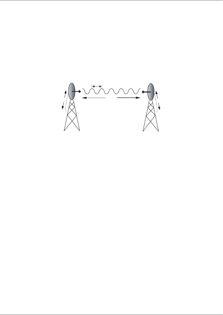
1. LINE-OF-SITE
The TRACER 4106 and 4206 systems are designed for operation in the license free 2.400 to 2.4835 GHz
and 5.725 to 5.850 GHz Industrial, Scientific, and Medical (ISM) bands. Radio wave propagation in these
bands exhibit microwave characteristics, which are ideally suited for point-to-point, line-of-sight
communications. Line-of-sight essentially requires that the transmitting antenna and receiving antenna are
able to “see” each other, and that the straight-line path between the two antennas is free of any
obstructions, such as buildings, trees, mountains, and, in longer paths, even the curvature of the earth.
2. DECIBELS
The received signal power equation is often expressed in a decibel (dB) format, which turns the power
multiplication and division operations into addition and subtraction operations. In general, any quantity
can be expressed in decibels. If the quantity (x) is a power level, the decibel equivalent is defined as
If the quantity x is referenced to a milliwatt (mW), then the decibel-milliwatt (dBm) is used instead of a
generic decibel.
3. RECEIVER POWER
The radio frequency (RF) signal power that is available at the input to the receiving TRACER 4106/4206
system is the next parameter of interest in analyzing a wireless path. The TRACER 4106/4206 has a
maximum output power level of 100 mW, which is equivalent to 20 dBm. This output signal will be
attenuated and distorted by various factors, all of which will degrade the original signal and affect the
signal strength and quality as sensed by the receiving unit. A simplified power budget analysis is beneficial
to perform after verifying a suitable line-of-sight path to determine if the microwave path is suitable, even
for ideal, non-distorted signals.
The equation relating received signal power to the other microwave parameters is
Point-to-Point Wireless communication from a single site to another
individual site. Contrast with point-to-multipoint
Line-of-Sight An unobstructed, direct path exists between the
transmitting and the receiving antennas.
xdB 10 log10 x()⋅ (dB)
xdBm 10 log10
x
1mW
-------------
⋅ (dBm)
PR
PTGTGRλ2
4π()
2d2L
---------------------------
(watts, W)

TRACER 4206 System Manual Section 2, Microwave Path Engineering Basics
612804206L1-1B © 2002 ADTRAN, Inc. 15
where the variables in the equation are defined as
PRreceived power (Watts)
PTtransmitted power (100 mW maximum for TRACER 4106/4206 - adjustable)
GTtransmit antenna gain
GRreceive antenna gain
λcarrier wavelength (c / ƒ) (meters)
dpath distance (meters)
Lother losses (RF coaxial cable, etc.)
The actual transmit and receive antenna gain values are strictly dependent upon the physical characteristics
of the antennas installed for each link. Typical gains are between 20 and 40 dB. For example, a 4 foot
diameter Parabolic dish has 34.2 dB of gain at 5.8 GHz. The carrier wavelength is the physical wavelength
of the main RF carrier being used for communication, and is usually approximated at the center frequency
of the band, which is 2441.75 or 5787.5 MHz. This gives a wavelength of 12.29 cm at 2441.75 MHz and
5.18 cm at 5787.5 MHz.
The FCC specifies the maximum transmitter power that may be used for antennae of a given gain. FCC
rules Part 15, Subpart 247 allow for a maximum power of 1 watt (30 dBm) into antennae of a gain less than
or equal to 6 dBi. At 2.4 GHz (TRACER 4106), the 1 watt maximum transmitter power must be reduced
by 1 dB for every 3 dB of antenna gain over 6 dBi. Since the TRACER 4106 maximum transmit power is
100 milliwatts, only antennas with gains above 36 dBi (12 foot diameter parabolic dishes) require any
reduction in transmit power. For the 5.8 GHz band (TRACER 4206), there is no reduction in transmitter
output power required for antennae gains greater than 6 dBi.
The path distance is simply the physical distance between the transmit and receive antennas. For the
TRACER 4106/4206 these distances can range up to 30 miles. The final parameter L incorporates all other
signal power losses in the microwave link, most of which are caused by antenna feed.
4. ANTENNA GAIN
Best performance will result from the use of a parabolic dish antenna. Antenna gain is determined by the
size of the dish, with typical features detailed below. Dish manufacturers will be able to supply gains for
other types of antennas.
Table 1. Antenna Gain for Given Dish Diameters
Dish Diameter
(in feet)
Gain at 2.4 GHz (in dBi)
(TRACER 4106)
Gain at 5.8 GHz (in dBi)
(TRACER 4206)
221 28.5
427 34.2
631 37.5
833 40.7
10 35 42.5
12 37 44.2

Section 2, Microwave Path Engineering Basics TRACER 4206 System Manual
16 © 2002 ADTRAN, Inc. 612804206L1-1B
5. PATH LOSS
The expression
where
fcarrier frequency (Hz)
λcarrier wavelength (c / f) (meters)
dpath distance (meters)
cspeed of light, free-space (meters)
is called the path loss, and increases rapidly as either path length increases or carrier wavelength decreases
(which happens as the carrier frequency increases). So, longer microwave paths will naturally experience
more path loss than shorter paths. Likewise, higher frequency microwave communication will experience
more path loss than lower frequency microwave communication.
Table 2, tabulates path loss values for various path lengths for both 2.4 GHz and 5.8 GHz systems. Values
not listed in the table can be interpolated from those listed.
When using decibel notation, the received power equation becomes
or
Table 2. Path Loss for Given Path Lengths
Path Length
(miles)
Path Loss 2.4 GHz
(dB)
Path Loss 5.8 GHz
(dB)
1104 112
2110 118
3114 121
4116 124
5118 126
10 124 132
15 128 135
20 130 138
25 132 140
30 134 141
35 135 143
LP
4πd
λ
----------
24πdf
c
------------
2
(dB)
PRPTGTGRL±20 · log10
± 4πdf
c
------------
(dBm)
PRPTGTGRL±LP
± (dBm)
TRACER 4206 System Manual Section 2, Microwave Path Engineering Basics
612804206L1-1B © 2002 ADTRAN, Inc. 17
Where, in the second equation the path loss has been lumped into a single quantity, LP
, as discussed
previously. When using decibel notation, it is necessary that all quantities are individually converted to
decibels prior to performing addition and subtraction.
When d is expressed in miles and f in GHz, the path loss expression in decibels becomes
Figure 1 illustrates a wireless link containing all of the parameters previously discussed.
Figure 1. Example Microwave Path with Parameters
6. ANTENNA ALIGNMENT
With line-of-sight microwave communications, optimum system performance requires that the
transmitting and receiving antennas are properly aligned. This will ensure maximum received signal power
at each receiver. Antenna alignment must be achieved in both azimuth (along a horizontal plane) and
elevation (along a vertical plane). A received signal strength indicator (RSSI) is used to aid the equipment
installer in determining when alignment is maximized, by simply ensuring maximum RSSI. The RSSI
indicator for the TRACER 4106/4206 system is provided through the VT100 terminal menus accessed
through the RS-232 interface, and is presented as a series of bars indicating signal strength. More bars
means more RSSI, which ensures more received signal strength and better link performance.
If the local system has acquired a useful signal from the remote system, then the remote TRACER
4106/4206 RSSI can also be viewed from the local TRACER 4106/4206 VT100 terminal menu interface.
An RSSI Test point is also provided on the front panel. The voltage (relative to the gnd test point) present
on this test point represents a relative signal level of receive strength from the far end. The voltage at this
test point can vary from approximatly 0 to greater than 4 Volts DC, with 0 Volts corresponding to no signal
and 4 Volts or better to full signal strength.
Antenna Beam Patterns
Directly related to the subject of antenna alignment is the topic of antenna beam patterns. Antennas being
used with the TRACER 4106/4206 system will have a particular beam shape determined in part by the
physical construction and geometry of the antenna. The antenna beam patterns are characterized by a
dominant main lobe, which is the preferred lobe to use for point-to-point communications, and several side
LP96.6 20 log10 d() 20·log10 f()⋅ (dB)
G
T
G
R
d, L
P
P
T
P
R
λ
L
L

Section 2, Microwave Path Engineering Basics TRACER 4206 System Manual
18 © 2002 ADTRAN, Inc. 612804206L1-1B
lobes, as shown in Figure 2 on page 18. The antenna alignment step to setting up a microwave link is in
fact steering the main lobes of both antennas until the main lobe of one transmitter is centered on the
receiving element of the receiving antenna.
Figure 2. Typical Antenna Beam Pattern
Antennas are also designed to radiate RF energy efficiently for a specific range of frequencies. Please
consult the data sheet for your particular antenna make and model to ensure that it is specified to operate in
the 2400 MHz to 2483.5 MHz frequency band for TRACER 4106 models, and the 5725 MHz to 5850
MHz frequency band for TRACER 4206 models.
Fresnel Zones, Earth Curvature, & Antenna Heights
The Fresnel zones correspond to regions in the microwave path where reflections of the intended signal
occur and combine in both constructive and destructive manners with the main signal, thereby either
enhancing or reducing the net power at the receiver.
In general, the odd numbered Fresnel zones (1, 3, 5, ...) add constructively at the receiver, while the even
numbered Fresnel zones (2, 4, 6, ...) add destructively at the receiver.
The first Fresnel zone corresponds to the main lobe, and must be at least 60% free of physical obstructions for
the path calculations to be valid. Since the main lobe contains the vast majority of the microwave energy, this
zone is typically used to determine proper antenna heights when placing antennas on towers or buildings.
The curvature of the Earth becomes a legitimate obstruction for path lengths of 7 miles or greater, and must
also be accounted for when determining minimum antenna heights.
The aggregate expression for minimum antenna height that incorporates both the 60% first Fresnel zone
and the Earth curvature is given by
where f is in GHz and d is in miles.
Table 3 tabulates minimum antenna heights for given path lengths.
main lobe
side lobes
h72.1 d
4f
----- 0.125d2
(feet)

TRACER 4206 System Manual Section 2, Microwave Path Engineering Basics
612804206L1-1B © 2002 ADTRAN, Inc. 19
Table 3. Minimum Antenna Height for Given Path Lengths
7. COAXIAL CABLE
Coaxial cable will be required to attach the TRACER 4106/4206 to the antenna. The length of the cable
will vary from a few feet to several feet, depending upon your application and the proximity of the
TRACER 4106/4206 to the antenna.
Various grades of coaxial cable will work sufficiently well for connecting the TRACER 4106/4206 unit to
the antenna. A low-loss coaxial cable is suggested to minimize cable losses. One end of the cable will
require an N-type male connector (plug) to mate with the TRACER 4106/4206 unit. The other end of the
coax will require a connector compatible with the antenna chosen for the installation, which is usually also
an N-type male connector (plug). Additionally, it is recommended that both connectors on the coaxial
cable be weatherproofed from the elements to prevent corrosion and electrical shorting.
Table 3 gives typical loss figures for some of the more common coaxial cable types, per 100 feet.
Path Length
(miles)
Min. Antenna Height
(ft)
222
432
641
850
10 60
14 81
16 92
18 104
20 117
22 131
24 145
26 161
28 177
30 194
32 213
34 232
36 252

Section 2, Microwave Path Engineering Basics TRACER 4206 System Manual
20 © 2002 ADTRAN, Inc. 612804206L1-1B
Table 4. Typical Coaxial Loss for Common Cable Types, per 100 ft.
In certain areas where lightning strikes are frequent, a lightning arrestor should be installed directly on the
antenna coax. This will help protect the RF electronics in the downstream path from damaging voltages
and currents, including the TRACER 4106/4206 unit.
8. RECEIVER SENSITIVITY
Receiver sensitivity is a value expressed in decibels referenced to one milliwatt (dBm) that corresponds to
the minimum amount of signal power needed at the receiver to achieve a given bit error rate (BER).
Receiver sensitivity is usually a negative number of decibels, and as such smaller receiver sensitivity
(higher quantity negative numbers) is better for a given BER. Several factors affect receiver sensitivity,
including the data bandwidth of the wireless link, and the amount of additional signal degradation
introduced in the receiver electronics. The receiver sensitivity of the TRACER 4106 is -93 dBm at 10-6 bit
error rate, while the receiver sensitivity of the TRACER 4206 is -90 dBm at 10-6 bit error rate.
Three software selectable band plans are provided for frequency agility, should an interferer be present
nearby. Changing the 4106/4206 bandplan does not require additional components, or opening of the
radio. See >TRACER System Configuration > RF Bandplan on page 47 for additional details.
Cable Type
2.4 GHz Loss/100 ft. (in dB)
(TRACER 4106)
5.8 GHz Loss/100 ft. (in dB)
(TRACER 4206)
RG58 80 N/A
RG8 (air) 20 N/A
RG8 (foam) 9 N/A
1/4” Coax 5.91 11.36
3/8” Coax 5.76 9.65
1/2” Coax 3.83 6.49
5/8” Coax 2.98 4.90
7/8” Coax 2.2 N/A
1 1/4” Coax 1.62 N/A
1 5/8” Coax 1.41 N/A
5.8 GHz Elliptical Waveguide N/A 1.23

TRACER 4206 System Manual Section 2, Microwave Path Engineering Basics
612804206L1-1B © 2002 ADTRAN, Inc. 21
9. FADE MARGIN
Fade margin is a value indicating the amount of extra signal power available to the receiver to operate at a
maximum bit error rate (BER). Higher levels of fade margin are better, and will protect the viability of the
microwave link against signal fading. For most applications, 20 to 30 dB of fade margin should ensure a
reliable link. Fade margin is simply the difference between the available signal power at the receiver and
the receiver sensitivity, discussed previously:
10. PATH AVAILABILITY
The path availability of a wireless link is a metric that expresses the fractional amount of time a link is
available over some fixed amount of time, and depends on several factors. Path availability is expressed as
where the parameters are
aterrain factor
bclimate factor
fcarrier frequency (GHz)
dpath length (miles)
Ffade margin (dB)
The terrain factor is a quantity that compensates the link availability for different types of terrain.
Generally speaking, the more smooth an area's terrain is, the less availability a wireless link running
over that terrain will have, primarily due to multipath reflections. In contrast, secondary microwave
signals will be randomly dispersed over rough terrain, and will not interfere with the main signal lobe
as badly as in the smooth terrain case. The terrain factor values normally used are listed below:
Terrain Terrain Factor Description
Smooth 4water, flat desert
Average 1moderate roughness
Mountainous 1/4 very rough, mountainous
FP
RPsens
±PRGTGRL±LP
±Psens
± (dB)
A1 2.5 10 6±
×()abfd310 F10⁄±
()±[]100%× (dB)

Section 2, Microwave Path Engineering Basics TRACER 4206 System Manual
22 © 2002 ADTRAN, Inc. 612804206L1-1B
The climate factor is a quantity that compensates the link availability for different types of climates
(weather). In general, microwave links operating in areas with high humidity will have less availability
than those in arid areas, primarily because water is a dispersive mechanism to microwave energy, and
causes the main signal lobe to refract and disperse away from the receiver location. The climate factor
values normally used are listed below.
Climate Climate Factor Description
Very Dry 1/8 desert regions
Temperate 1/4 mainland, interior region
Humid 1/2 humid and coastal regions

612804206L1-1B © 2002 ADTRAN, Inc. 23
ENGINEERING GUIDELINES
CONTENTS
Equipment Dimensions . . . . . . . . . . . . . . . . . . . . . . . . . . . . . . . . . . . . . . . . . . . . . . . . . . . . . . . . . . 24
Power Requirements . . . . . . . . . . . . . . . . . . . . . . . . . . . . . . . . . . . . . . . . . . . . . . . . . . . . . . . . . . . . 24
Reviewing the Front Panel Design . . . . . . . . . . . . . . . . . . . . . . . . . . . . . . . . . . . . . . . . . . . . . . . . . 24
RSSI Monitoring Interface . . . . . . . . . . . . . . . . . . . . . . . . . . . . . . . . . . . . . . . . . . . . . . . . . . . . . . 24
TX PWR Monitoring Interface . . . . . . . . . . . . . . . . . . . . . . . . . . . . . . . . . . . . . . . . . . . . . . . . . . . 25
Front Panel LEDs . . . . . . . . . . . . . . . . . . . . . . . . . . . . . . . . . . . . . . . . . . . . . . . . . . . . . . . . . . . . 25
Reviewing the TRACER 4106/4206 Rear Panel Design . . . . . . . . . . . . . . . . . . . . . . . . . . . . . . . . . 26
Antenna Interface . . . . . . . . . . . . . . . . . . . . . . . . . . . . . . . . . . . . . . . . . . . . . . . . . . . . . . . . . . . . 26
Fuse . . . . . . . . . . . . . . . . . . . . . . . . . . . . . . . . . . . . . . . . . . . . . . . . . . . . . . . . . . . . . . . . . . . . . . 26
DC Power Connection. . . . . . . . . . . . . . . . . . . . . . . . . . . . . . . . . . . . . . . . . . . . . . . . . . . . . . . . . 27
Alarm Contacts . . . . . . . . . . . . . . . . . . . . . . . . . . . . . . . . . . . . . . . . . . . . . . . . . . . . . . . . . . . . . . 27
T1 Connections . . . . . . . . . . . . . . . . . . . . . . . . . . . . . . . . . . . . . . . . . . . . . . . . . . . . . . . . . . . . . . 27
RS-232 Connection (Terminal Use) . . . . . . . . . . . . . . . . . . . . . . . . . . . . . . . . . . . . . . . . . . . . . . 28
RS-232 Connection (Modem Use) . . . . . . . . . . . . . . . . . . . . . . . . . . . . . . . . . . . . . . . . . . . . . . . 29
At-A-Glance Specifications . . . . . . . . . . . . . . . . . . . . . . . . . . . . . . . . . . . . . . . . . . . . . . . . . . . . . . . 30
FIGURES
Figure 1. TRACER 4206 Front Panel Layout . . . . . . . . . . . . . . . . . . . . . . . . . . . . . . . . . . . . . . . . 24
Figure 2. TRACER 4106/4206 Rear Panel Layout . . . . . . . . . . . . . . . . . . . . . . . . . . . . . . . . . . . . 26
TABLES
Table 1. TRACER 4106/4206 Front Panel Description . . . . . . . . . . . . . . . . . . . . . . . . . . . . . . . . . 25
Table 2. TRACER 4106/4206 LEDs . . . . . . . . . . . . . . . . . . . . . . . . . . . . . . . . . . . . . . . . . . . . . . . 25
Table 3. DC Power Connector Pinout . . . . . . . . . . . . . . . . . . . . . . . . . . . . . . . . . . . . . . . . . . . . . . 27
Table 4. Alarm Contact Connector Pinout . . . . . . . . . . . . . . . . . . . . . . . . . . . . . . . . . . . . . . . . . . . 27
Table 5. T1 Interface Connector Pinout . . . . . . . . . . . . . . . . . . . . . . . . . . . . . . . . . . . . . . . . . . . . 27
Table 6. RS-232 Connection Pinout . . . . . . . . . . . . . . . . . . . . . . . . . . . . . . . . . . . . . . . . . . . . . . . 28
Table 7. TRACER 4106/4206 (DCE) to Terminal (DTE) Diagram (DB-25) . . . . . . . . . . . . . . . . . . 28
Table 8. TRACER 4106/4206 (DCE) to Personal Computer (DB-9) . . . . . . . . . . . . . . . . . . . . . . . 29
Table 9. TRACER 4106/4206 (DCE) to Modem (DCE) . . . . . . . . . . . . . . . . . . . . . . . . . . . . . . . . 30
Section 3, Engineering Guidelines TRACER 4206 System Manual
24 © 2002 ADTRAN, Inc. 612804206L1-1B
1. EQUIPMENT DIMENSIONS
The TRACER 4106/4206 unit is 17.12” W, 9.34” D, and 1.72” H, weighs 7 lbs, and can be used in
rack-mount configurations.
2. POWER REQUIREMENTS
The TRACER 4106/4206 system has a maximum power consumption of 20W and a maximum current
draw of 0.95A (at 21 VDC).
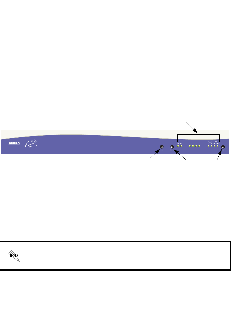
3. REVIEWING THE FRONT PANEL DESIGN
The front panel contains RSSI and TX PWR monitoring interfaces, a GND interface for reference with the
monitoring interfaces, and status LEDs to provide visual information about the TRACER 4106/4206
system. Figure 1 identifies the various bantam interfaces and the LEDs.
Figure 1. TRACER 4206 Front Panel Layout
RSSI Monitoring Interface
The RSSI voltage is a function of the signal strength at the receiver and is used to measure the received
signal strength. RSSI varies approximately from 0 to greater than 4 Volts (V), with 0V corresponding to a
weaker received signal and 4V or better corresponding to a stronger received signal.
The voltage level present at the RSSI test point represents only a relative signal level of
receive strength from the far end. No direct correlation can be made between RSSI voltage
levels and actual receive levels in dBm. This test point is provided to assess relative signal
level for alignment of antennas.
ALARM
T1A T1B T1C T1D
TRACER 4206
Status LEDs
TX PWR
RSSI GND

TRACER 4206 System Manual Section 3, Engineering Guidelines
612804206L1-1B © 2002 ADTRAN, Inc. 25
TX PWR Monitoring Interface
The TX PWR voltage is a function of the selected transmit power level. This voltage ranges approximately
from 0 to 5V, with 0V corresponding to +5 dBm (3 milliwatts) and 5V corresponding to +20 dBm (100
milliwatts).
Front Panel LEDs
With the TRACER 4106/4206 powered-on, the front panel LEDs provide visual information about the
status of the TRACER 4106/4206 system. Table 1 provides a brief description of the front panel features,
and Table 2 (continued on page 27) provides detailed information about the LEDs.
Table 1. TRACER 4106/4206 Front Panel Description
Feature Description
RSSI Interface DC voltage indicating strength of the received signal at the antenna
TX PWR Interface DC voltage indicating strength of transmitted signal
GND Interface Ground reference for RSSI and TX PWR interfaces
Status LEDs Provides status information about the system
Table 2. TRACER 4106/4206 LEDs
For these LEDs... This color light... Indicates that...
PWR Green (solid) the TRACER 4106/4206 is connected to a power source.
Off the TRACER 4106/4206 is not currently powered up.
PLAN A Green (solid) the TRACER 4106/4206 is transmitting on Frequency Plan A.
Off the TRACER 4106/4206 is not transmitting on Frequency
Plan A.
PLAN B Green (solid) the TRACER 4106/4206 is transmitting on Frequency Plan B.
Off the TRACER 4106/4206 is not transmitting on Frequency
Plan B.
RF DOWN Red (solid) there is a communication problem between the local and remote
TRACER 4106/4206 systems.
T1 Alarms
T1A
T1B
T1C
T1D
Red (solid) an Alarm Condition on a T1 Interface. Check the respective T1
status page to identify the active alarm.
Red (blinking) the respective T1 is in a loopback mode.
RF LOW Red (solid) the RSSI level is below suggested minimum threshold.
TST Amber (solid) there is an active test being performed by the system or there is
an active loopback.
Section 3, Engineering Guidelines TRACER 4206 System Manual
26 © 2002 ADTRAN, Inc. 612804206L1-1B
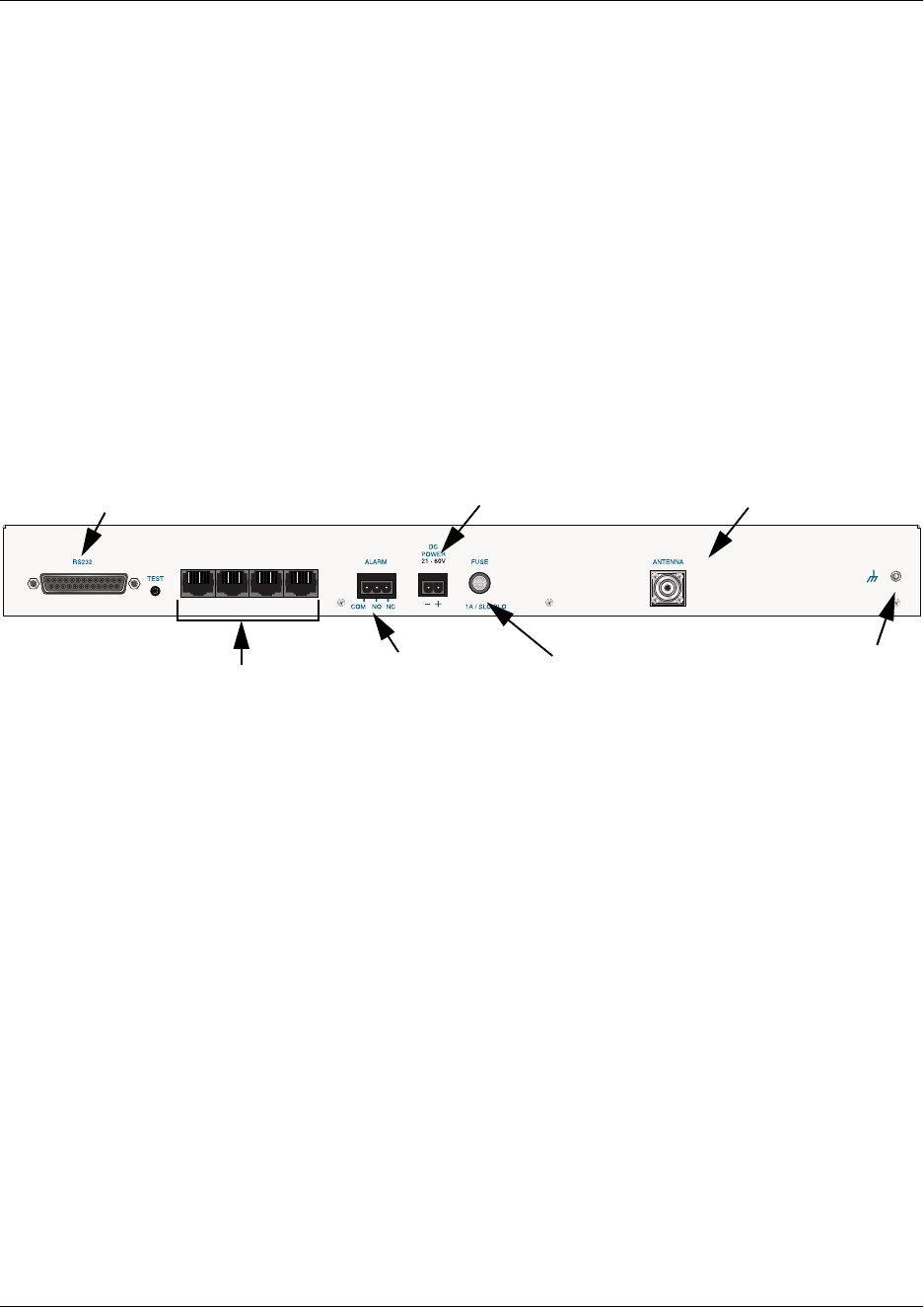
4. REVIEWING THE TRACER 4106/4206 REAR PANEL DESIGN
The TRACER 4106/4206 rear panel contains the following interfaces:
•ALARM interface (terminal block) for connecting to an external alarm monitoring system
•DC POWER (terminal block) for connecting to a proper 21-60 VDC power source
•T1A, T1B, T1C and T1D (RJ-48C jacks) for connecting to a T1 device
•ANTENNA (N-Type connector) for the antenna feedline cable
•TEST (1/4” stereo jack) for QPSK constellation test point
• Ground lug for connecting to earth ground
•RS-232 (DB-25 female) for connecting to a VT100 terminal or PC with terminal emulation
software
Figure 2 on page 26 identifies the various features of the TRACER 4106/4206 rear panel. A detailed
discussion of all interfaces (including pinouts, where applicable) follows the figure.
Figure 2. TRACER 4106/4206 Rear Panel Layout
Antenna Interface
The ANTENNA interface (N-Type connector) connects to the antenna (customer supplied) using standard
antenna feedline cable. When determining the cable specifications for your application, refer to Section 2,
Microwave Path Engineering Basics (Coaxial Cable on page 19) for a discussion on cable length and loss
factors.
Fuse
The fuse holder, accessible from the rear panel of the TRACER 4106/4206, accepts a generic 1 Amp, 250
Volt, 2-inch slow-blo fuse.
T1A T1B T1C T1D
Antenna
DC Power
Connection Connector
T1 Interfaces
RS232 Interface
(VT100 Terminal)
Ground
Lug
Fuse
Alarm
Contacts

TRACER 4206 System Manual Section 3, Engineering Guidelines
612804206L1-1B © 2002 ADTRAN, Inc. 27
DC Power Connection
The TRACER 4106/4206 can operate from a supply between 21 and 60 VDC, with either polarity
referenced to ground, and consumes less than 20 Watts (W). Power supplies should be able to provide up to
30 W at the selected voltage. Current required (in amps) is determined by dividing the power consumed (in
watts) by the applied voltage (in volts). For example, at 48 V, TRACER 4106/4206 would draw
approximately 0.42 A (25 W/48 V).
Alarm Contacts
Normally open (NO) and normally closed (NC) alarm contacts are provided on the rear panel of the
TRACER 4106/4206 system. In normal operation, the NC contact is electrically connected to the common
contact (COM) and the NO contact is isolated. During an alarm condition, the NC contact becomes
isolated and the NO is electrically connected to COM. This allows alarm conditions to be reported to
external alarm monitoring systems.
T1 Connections
The physical T1 interfaces are provided by 4 RJ-48C jacks that comply with the applicable ANSI and
AT&T ® standards.
Connector type Plug-in Terminal Block
Table 3. DC Power Connector Pinout
PIN NAME DESCRIPTION
1+ POSITIVE LEAD (referenced to ground)
2- NEGATIVE LEAD (referenced to ground)
Connector type Plug-in Terminal Block
Table 4. Alarm Contact Connector Pinout
PIN NAME DESCRIPTION
1COM COMMON CONTACT
2NO NORMALLY-OPEN CONTACT
3NC NORMALLY-CLOSED CONTACT
Connector type RJ-48C
Table 5. T1 Interface Connector Pinout
PIN NAME DESCRIPTION
1 R Transmit data (ring) towards the network
2 T Transmit data (tip) towards the network
3, 6-8 UNUSED ——
4R1 Receive data (ring) toward the network
5T1 Transmit data (tip) from the network

Section 3, Engineering Guidelines TRACER 4206 System Manual
28 © 2002 ADTRAN, Inc. 612804206L1-1B
RS-232 Connection (Terminal Use)
The RS-232 connector provides a female DB-25 terminal connection (wired as a DCE interface), which is
used for terminal access to the TRACER 4106/4206 system. The RS-232 port provides the following
functions:
• Accepts EIA-232 input from a PC or terminal for controlling the TRACER 4106/4206 system
• Operates at 9600 bps
Tab le 6 on page 28 shows the pinout. Wiring diagrams for connecting to the RS-232 connector (for
various applications) are provided following the pinout.
Connector type DB-25
Table 6. RS-232 Connection Pinout
PIN NAME DESCRIPTION
1, 7 GND GROUND
2 TX TRANSMIT
3 RX RECEIVE
4 RTS REQUEST TO SEND
5 CTS CLEAR TO SEND
6 DSR DATA SET READY (MODEM CONTROL ONLY)
8 CD CARRIER DETECT
9-19 — UNUSED
20 DTR DATA TERMINAL READY (MODEM CONTROL ONLY)
21 — UNUSED
22 RI RING INDICATOR
23-25 — UNUSED
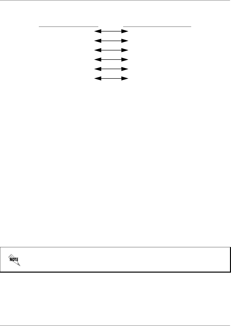
Table 7. TRACER 4106/4206 (DCE) to Terminal (DTE) Diagram (DB-25)
PIN NAME PIN NAME
2TX 2TX
3RX 3RX
4RTS 4RTS
5CTS 5CTS
6DSR 6DSR
7GND 7GND
TRACER 4206 System Manual Section 3, Engineering Guidelines
612804206L1-1B © 2002 ADTRAN, Inc. 29
RS-232 Connection (Modem Use)
Modem controls, discussed in Section 5, User Interface Guide, of this manual, will enable or disable
modem control through the RS-232 interface. When this option is enabled from a standard terminal
connection, all RS-232 communications will cease until a modem is attached with a null modem adapter
between the TRACER 4106/4206 and the data modem. The data modem should be configured for AUTO
ANSWER and 9600 bps. When the user connects via modem to the TRACER 4106/4206 unit,
communications via the RS-232 port will resume. If a user accidentally enables modem control from a
terminal and disrupts the RS-232 communication, pressing <Ctrl + Z> three times will temporarily disable
the modem control option (until the system is reset) and access the system configuration to disable modem
control.
The TRACER 4106/4206 must be interfaced to a modem via an RS-232 null modem adapter or cable. The
null modem will convert Clear To Send (CTS) and Data Set Ready (DSR) into Ready To Send (RTS) and
Data Terminal Ready (DTR), respectively. These signals will indicate (to most modems) that a valid DTE
terminal device is present. The null modem interface must route Carrier Detect (CD) on pin 8 directly from
the modem, and the modem must source CD only when actually connected to a carrier when using the
RS-232 interface for modem control.
When MODEM CONNECTION (logout) is selected in the menu system, the TRACER 4106/4206 will de-assert
DTR and DSR for a time greater than 20 ms. The null modem will consequently drop DTR and RTS at the
modem interface, signaling the modem to hang up the line. If password functionality is enabled in the
TRACER 4106/4206, selecting MODEM CONNECTION (logout) will reset the TRACER 4106/4206 to the
password entry screen.
Tab le 9 on page 30 contains the wiring diagram needed for connecting the TRACER 4106/4206 RS-232
interface to a modem using the null modem adapter.
Table 8. TRACER 4106/4206 (DCE) to Personal Computer (DB-9)
PIN NAME PIN NAME
2TX 2TX
3RX 3RX
4RTS 7RTS
5CTS 8CTS
6DSR 6DSR
7GND 5GND
Hangup-on-DTR-drop may need to be explicitly enabled on some modems.
Section 3, Engineering Guidelines TRACER 4206 System Manual
30 © 2002 ADTRAN, Inc. 612804206L1-1B
5. AT-A-GLANCE SPECIFICATIONS
The following is a list of specifications for the TRACER 4106/4206 system.
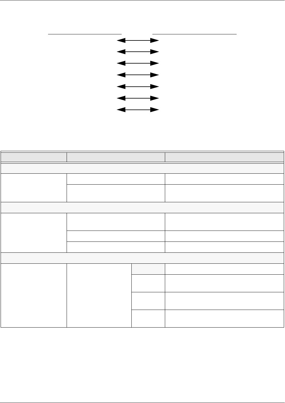
Table 9. TRACER 4106/4206 (DCE) to Modem (DCE)
PIN NAME PIN NAME
2TX 3RX
3RX 2TX
4RTS 5CTS
5CTS 4RTS
6DSR 20 DTR
7GND 7GND
8CD 8CD
Hardware Description Specification
Transmitter
Output Power +20 dBm, max
Frequency Range 2400 to 2483.5 MHz (4106)
5725 to 5850 MHz (4206)
Receiver
Receive Level, Minimum -93 dBm (TRACER 4106)
-90 dBm (TRACER 4206)
Receive Level, Maximum -30 dBm
Receive Level, Nominal -55 dBm
Frequency Plan
Plan A
Band Plan
1Tx 2.416 GHz, Rx 2.456 GHz (4106)
Tx 5.734 GHz, Rx 5.814 GHz (4206)
2Tx 2.422 GHz, Rx 2.462 GHz (4106)
Tx 5.744 GHz, Rx 5.824 GHz (4206)
3Tx 2.428 GHz, Rx 2.468 GHz (4106)
Tx 5.753 GHz, Rx 5.833 GHz (4206)

TRACER 4206 System Manual Section 3, Engineering Guidelines
612804206L1-1B © 2002 ADTRAN, Inc. 31
Frequency Plan (continued
Plan B
Band Plan
1Tx 2.456 GHz, Rx 2.416 GHz (4106)
Tx 5.814 GHz, Rx 5.734 GHz (4206)
2Tx 2.462 GHz, Rx 2.422 GHz (4106)
Tx 5.824 GHz, Rx 5.744 GHz (4206)
3Tx 2.468 GHz, Rx 2.428 GHz (4106)
Tx 5.833 GHz, Rx 5.753 GHz (4206)
T1 Interface
Capacity 1.544 Mbps (each)
Connection RJ-48C jacks
Line Code B8ZS, AMI
Framing ESF, D4
Alarms AIS, Red, Yellow, BPVs, LOS
Loopbacks Local and remote (line and link)
User Interface
Panel Alarm LEDs
Diagnostics Line and Link Loopbacks
Test Points QPSK Constellation, RSSI, Tx PWR
Alarms Normally Open (NO) and Normally Closed (NC)
VT100 Terminal Menu Driven User Interface, Control of the
Remote End, Loopback Test, Optional
Password Protection, Event History
VT100 Terminal Interface
Data Rate 9600 bps
Data Bits 8
Parity None
Stop Bits 1
Terminal Emulation VT100
Mechanical and Environmental
Operating Temperature -25° C to 65° C
Size 17.12” W x 9.34” D x 1.72” H
Humidity 95%, Non-condensing
Hardware Description Specification

Section 3, Engineering Guidelines TRACER 4206 System Manual
32 © 2002 ADTRAN, Inc. 612804206L1-1B
Mechanical and Environmental (continued)
Weight 7 lbs
Power
Input Voltage 21 to 60 VDC, either polarity referenced to
ground
Power Consumption < 20 Watts
Connector 2 pin terminal block (DC)
Fuse 1 amp, 250 Volt slow-blo fuse (2-inch)
Hardware Description Specification

612804206L1-1B © 2002 ADTRAN, Inc. 33
NETWORK TURNUP PROCEDURE
CONTENTS
Introduction . . . . . . . . . . . . . . . . . . . . . . . . . . . . . . . . . . . . . . . . . . . . . . . . . . . . . . . . . . . . . . . . . . . . 34
Tools Required . . . . . . . . . . . . . . . . . . . . . . . . . . . . . . . . . . . . . . . . . . . . . . . . . . . . . . . . . . . . . . . . . 34
Unpack and Inspect the System . . . . . . . . . . . . . . . . . . . . . . . . . . . . . . . . . . . . . . . . . . . . . . . . . . . 34
Contents of ADTRAN Shipment . . . . . . . . . . . . . . . . . . . . . . . . . . . . . . . . . . . . . . . . . . . . . . . . . 34
Customer Provides . . . . . . . . . . . . . . . . . . . . . . . . . . . . . . . . . . . . . . . . . . . . . . . . . . . . . . . . . . . 34
Channel Selection . . . . . . . . . . . . . . . . . . . . . . . . . . . . . . . . . . . . . . . . . . . . . . . . . . . . . . . . . . . . . . 35
Grounding Instructions . . . . . . . . . . . . . . . . . . . . . . . . . . . . . . . . . . . . . . . . . . . . . . . . . . . . . . . . . . 36
Supplying Power to the Unit . . . . . . . . . . . . . . . . . . . . . . . . . . . . . . . . . . . . . . . . . . . . . . . . . . . . . . 37
Mounting Options . . . . . . . . . . . . . . . . . . . . . . . . . . . . . . . . . . . . . . . . . . . . . . . . . . . . . . . . . . . . . . . 37
Connecting the T1 Interface . . . . . . . . . . . . . . . . . . . . . . . . . . . . . . . . . . . . . . . . . . . . . . . . . . . . . . 37
FIGURES
Figure 1. 2.4 GHz Bandwidth Division (TRACER 4106) . . . . . . . . . . . . . . . . . . . . . . . . . . . . . . . . 35
Figure 2. 5.8 GHz Bandwidth Division (TRACER 4206) . . . . . . . . . . . . . . . . . . . . . . . . . . . . . . . . 35
Section 4, Network Turnup Procedure TRACER 4206 System Manual
34 © 2002 ADTRAN, Inc. 612804206L1-1B
1. INTRODUCTION
This section discusses the installation process of the TRACER 4106/4206 system.
2. TOOLS REQUIRED
The tools required for the installation of the TRACER 4106/4206 are:
• VT100 terminal or PC with terminal emulation software
• RS-232 (DB-25 male for TRACER 4106/4206 end) cable for connecting to terminal
3. UNPACK AND INSPECT THE SYSTEM
Each TRACER 4106/4206 is shipped in its own cardboard shipping carton. Open each carton carefully and
avoid deep penetration into the carton with sharp objects.
After unpacking the unit, inspect it for possible shipping damage. If the equipment has been damaged in
transit, immediately file a claim with the carrier, then contact ADTRAN Customer Service (see Customer
Service, Product Support Information, and Training information in the front of this manual).
Contents of ADTRAN Shipment
Your ADTRAN shipment includes the following items:
• TRACER 4102 or TRACER 4206 unit
• TRACER 4106/4206 Documentation CD
• 4 T1 Interconnect Cables (RJ-48C Straight-Through)
Customer Provides
The following items are necessary for the installation of the TRACER 4106/4206 system and are not
provided by ADTRAN:
• 21 to 60 VDC power source (or AC adapter available from ADTRAN P/N 1280650L1), either polarity
referenced to ground
• Antenna and mounting hardware
• Antenna feedline cable
Changes or modifications not expressly approved by ADTRAN could void the user’s
authority to operate the equipment.
To prevent electrical shock, do not install equipment in a wet location or during a lightning
storm.
TRACER 4206 System Manual Section 4, Network Turnup Procedure
612804206L1-1B © 2002 ADTRAN, Inc. 35
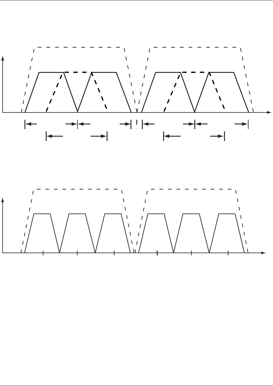
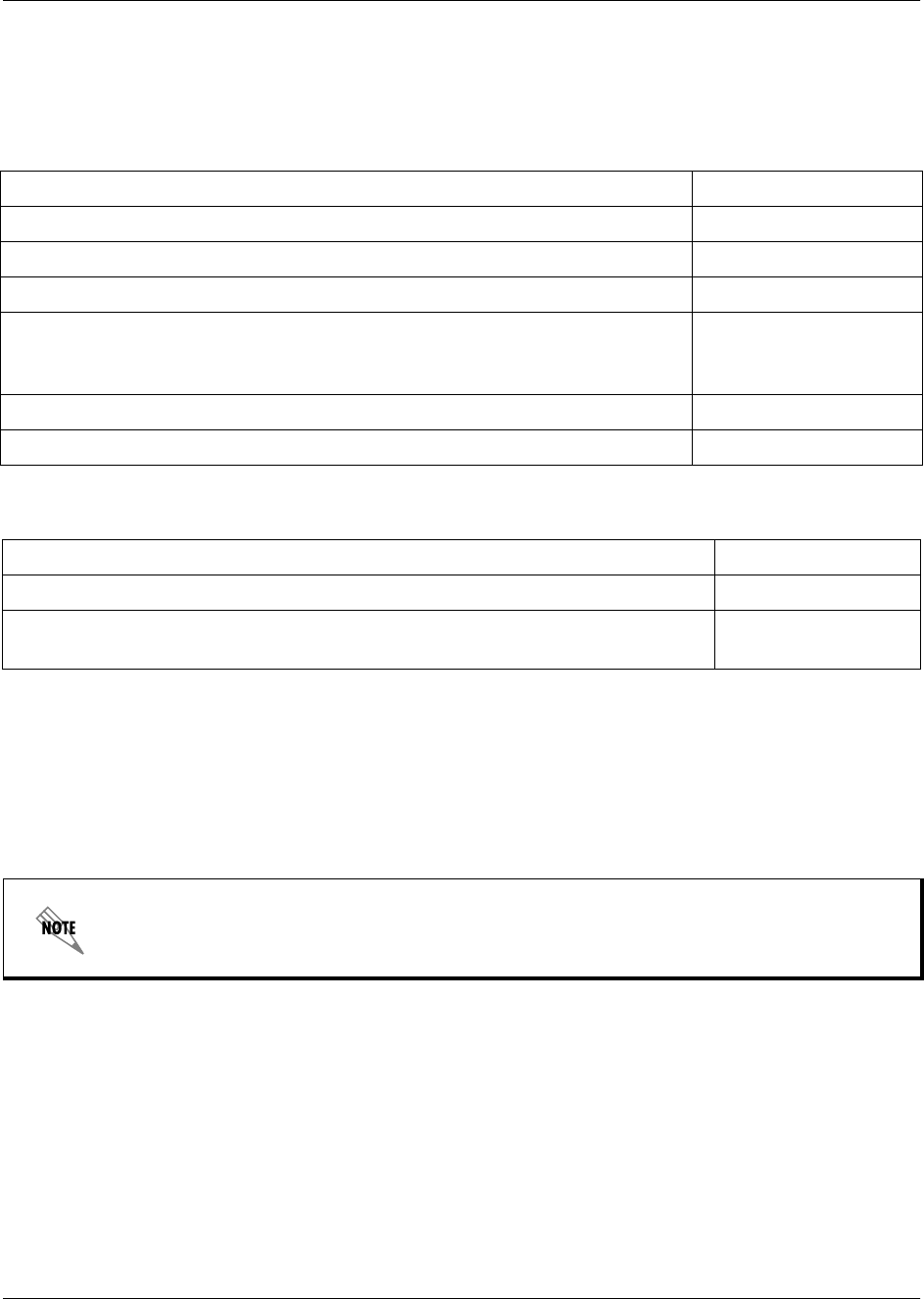
4. CHANNEL SELECTION
The FCC has allocated 83.5 MHz of spectrum in the 2.4 GHz band where the TRACER 4106 operates, and
125 MHz of spectrum in the 5.8 GHz band where the TRACER 4206 operates. Figure 1 and Figure 2
illustrate the bandwidth division.
Figure 1. 2.4 GHz Bandwidth Division (TRACER 4106)
Figure 2. 5.8 GHz Bandwidth Division (TRACER 4206)
To designate the utilization of the ISM bandwidth, there are two different channel plans, labeled A and B.
The letter of each channel plan setting is preset by the factory and refers to the physical configuration of
the diplexer filter inside the environmental housing. Each channel is then divided into three bandplans (1, 2
or 3). The bandplans must be the same for the local and remote TRACER 4106/4206. For example, the
transmitter at one end of the link will transmit in bandplan 1 of channel A (the lower portion of the
spectrum) and receive in bandplan 1 of channel B (the upper portion). Consequently, the receiver at the
other end should receive in bandplan 1 of channel A (the lower portion) and transmit in bandplan 1 of
channel B (the upper portion).
Channel A
2416 2441.752422 24282400 MHz 2483.5 MHz
Bandplan 3
Bandplan 2
Bandplan 1
Channel B
2456 2462 2468
Bandplan 3
Bandplan 2
Bandplan 1
Channel A
57345725 5787 58505744 5753MHz MHz
Bandplan 3Bandplan 2Bandplan 1
Channel B
5814 5824 5833
Bandplan 3Bandplan 2Bandplan 1

Section 4, Network Turnup Procedure TRACER 4206 System Manual
36 © 2002 ADTRAN, Inc. 612804206L1-1B
The letter of the channel plan (A or B) must be different on both ends and the number of the bandplan (1, 2,
or 3) must be the same on both ends. The default bandplan configuration for the TRACER 4106/4206 is
bandplan 1.
The channel plan (A or B) of the unit may be changed in the field if necessary by rewiring the internal
diplexer. Contact ADTRAN Technical Support for more information on this procedure.
5. GROUNDING INSTRUCTIONS
The following provides grounding instruction information from the Underwriters’ Laboratory UL 60950
Standard for Safety of Information Technology Equipment Including Electrical Business Equipment, of
December, 2000.
An equipment grounding conductor that is not smaller in size than the ungrounded branch-circuit supply
conductors is to be installed as part of the circuit that supplies the product or system. Bare, covered, or
insulated grounding conductors are acceptable. Individually covered or insulated equipment grounding
conductors shall have a continuous outer finish that is either green, or green with one or more yellow
stripes. The equipment grounding conductor is to be connected to ground at the service equipment.
The attachment-plug receptacles in the vicinity of the product or system are all to be of a grounding type,
and the equipment grounding conductors serving these receptacles are to be connected to earth ground at
the service equipment.
A supplementary equipment grounding conductor shall be installed between the product or system and
ground that is in addition to the equipment grounding conductor in the power supply cord.
The supplementary equipment grounding conductor shall not be smaller in size than the ungrounded
branch-circuit supply conductors. The supplementary equipment grounding conductor shall be connected
to the product at the terminal provided, and shall be connected to ground in a manner that will retain the
ground connection when the product is unplugged from the receptacle. The connection to ground of the
supplementary equipment grounding conductor shall be in compliance with the rules for terminating
bonding jumpers at Part K or Article 250 of the National Electrical Code, ANSI/NFPA 70. Termination of
the supplementary equipment grounding conductor is permitted to be made to building steel, to a metal
electrical raceway system, or to any grounded item that is permanently and reliably connected to the
electrical service equipment ground.
The supplemental grounding conductor shall be connected to the equipment using a number 8 ring terminal
and should be fastened to the grounding lug provided on the rear panel of the equipment. The ring terminal
should be installed using the appropriate crimping tool (AMP P/N 59250 T-EAD Crimping Tool or
equivalent.)
The supplemental equipment grounding terminal is located on the rear panel of the
TRACER 4106/4206.

TRACER 4206 System Manual Section 4, Network Turnup Procedure
612804206L1-1B © 2002 ADTRAN, Inc. 37
6. SUPPLYING POWER TO THE UNIT
The TRACER 4106/4206 can operate from a supply between 21 and 60 VDC, with either polarity
referenced to ground. Power supplies should be able to provide up to 30 watts at the selected voltage. A
dual pin terminal plug accepts power at the rear panel of the unit, providing a + and - polarity reference
point. Adapters for this plug are available (P/N 1175043L2) and are furnished with the unit and optional
power supply (P/N 1280650L1).
7. MOUNTING OPTIONS
Install the TRACER 4106/4206 in a location that requires minimal antenna feedline length (the loss in this
cable directly affects overall system performance). The TRACER 4106/4206 is designed to be mounted in
a rack. If multiple units are installed in one location, one half inch of spacing is recommended above and
below the unit.
8. CONNECTING THE T1 INTERFACE
The physical T1 interface is provided using 4 RJ-48C jacks for transmit and receive. The provided straight
through T1 interface cables can be used to interface to any standard T1 DTE device.
• This unit shall be installed in accordance with Article 400 and 364.8 of the NEC NFPA
70 when installed outside of a Restricted Access Location (i.e., central office, behind a
locked door, service personnel only area).
• Power to the TRACER 4106/4206 DC system must be from a reliably grounded
21-60 VDC source which is electrically isolated from the AC source.
• The branch circuit overcurrent protection shall be a fuse or circuit breaker rated min-
imum 60 VDC, maximum 10A.
• A readily accessible disconnect device that is suitably approved and rated shall be in-
corporated in the field wiring.

Section 4, Network Turnup Procedure TRACER 4206 System Manual
38 © 2002 ADTRAN, Inc. 612804206L1-1B

612804206L1-1B © 2002 ADTRAN, Inc. 39
USER INTERFACE GUIDE
CONTENTS
Navigating the Terminal Menu . . . . . . . . . . . . . . . . . . . . . . . . . . . . . . . . . . . . . . . . . . . . . . . . . . . . 41
Terminal Menu Window . . . . . . . . . . . . . . . . . . . . . . . . . . . . . . . . . . . . . . . . . . . . . . . . . . . . . . . 41
Navigating using the Keyboard Keys . . . . . . . . . . . . . . . . . . . . . . . . . . . . . . . . . . . . . . . . . . . . . 42
Terminal Menu and System Control . . . . . . . . . . . . . . . . . . . . . . . . . . . . . . . . . . . . . . . . . . . . . . . .42
Password Protection . . . . . . . . . . . . . . . . . . . . . . . . . . . . . . . . . . . . . . . . . . . . . . . . . . . . . . . . . . 42
Menu Descriptions . . . . . . . . . . . . . . . . . . . . . . . . . . . . . . . . . . . . . . . . . . . . . . . . . . . . . . . . . . . . . . 43
>TRACER System Status . . . . . . . . . . . . . . . . . . . . . . . . . . . . . . . . . . . . . . . . . . . . . . . . . . . . . . 43
>Main Menu . . . . . . . . . . . . . . . . . . . . . . . . . . . . . . . . . . . . . . . . . . . . . . . . . . . . . . . . . . . . . . . . 45
>TRACER System Configuration . . . . . . . . . . . . . . . . . . . . . . . . . . . . . . . . . . . . . . . . . . . . . . . . 46
>TRACER Link Performance History . . . . . . . . . . . . . . . . . . . . . . . . . . . . . . . . . . . . . . . . . . . . . 49
>T1A Status/Configuration/Loopback . . . . . . . . . . . . . . . . . . . . . . . . . . . . . . . . . . . . . . . . . . . . . 50
>T1A Performance History . . . . . . . . . . . . . . . . . . . . . . . . . . . . . . . . . . . . . . . . . . . . . . . . . . . . . 52
>T1B Status/Configuration/Loopback . . . . . . . . . . . . . . . . . . . . . . . . . . . . . . . . . . . . . . . . . . . . . 53
>T1B Performance History . . . . . . . . . . . . . . . . . . . . . . . . . . . . . . . . . . . . . . . . . . . . . . . . . . . . . 54
>T1C Status/Configuration/Loopback . . . . . . . . . . . . . . . . . . . . . . . . . . . . . . . . . . . . . . . . . . . . . 55
>T1C Performance History . . . . . . . . . . . . . . . . . . . . . . . . . . . . . . . . . . . . . . . . . . . . . . . . . . . . . 58
>T1D Status/Configuration/Loopback . . . . . . . . . . . . . . . . . . . . . . . . . . . . . . . . . . . . . . . . . . . . . 59
>T1D Performance History . . . . . . . . . . . . . . . . . . . . . . . . . . . . . . . . . . . . . . . . . . . . . . . . . . . . . 61
FIGURES
Figure 1. Main Menu Screen . . . . . . . . . . . . . . . . . . . . . . . . . . . . . . . . . . . . . . . . . . . . . . . . . . . . . 41
Figure 2. TRACER System Status . . . . . . . . . . . . . . . . . . . . . . . . . . . . . . . . . . . . . . . . . . . . . . . . 43
Figure 3. Main Menu . . . . . . . . . . . . . . . . . . . . . . . . . . . . . . . . . . . . . . . . . . . . . . . . . . . . . . . . . . . 45
Figure 4. TRACER System Configuration . . . . . . . . . . . . . . . . . . . . . . . . . . . . . . . . . . . . . . . . . . . 46
Figure 5. 2.4 GHz Bandwidth Division (TRACER 4106) . . . . . . . . . . . . . . . . . . . . . . . . . . . . . . . . 47
Figure 6. 5.8 GHz Bandwidth Division (TRACER 4206) . . . . . . . . . . . . . . . . . . . . . . . . . . . . . . . . 47
Figure 7. TRACER Link Performance History . . . . . . . . . . . . . . . . . . . . . . . . . . . . . . . . . . . . . . . . 49
Figure 8. T1A Status/Configuration/Loopback . . . . . . . . . . . . . . . . . . . . . . . . . . . . . . . . . . . . . . . 50
Figure 9. T1A Link Loopback . . . . . . . . . . . . . . . . . . . . . . . . . . . . . . . . . . . . . . . . . . . . . . . . . . . . 51
Figure 10. T1A Line Loopback . . . . . . . . . . . . . . . . . . . . . . . . . . . . . . . . . . . . . . . . . . . . . . . . . . . . 51
Figure 11. T1A Link Performance History . . . . . . . . . . . . . . . . . . . . . . . . . . . . . . . . . . . . . . . . . . . . 52
Figure 12. T1B Status/Configuration/Loopback . . . . . . . . . . . . . . . . . . . . . . . . . . . . . . . . . . . . . . . 53
Figure 13. T1B Link Loopback . . . . . . . . . . . . . . . . . . . . . . . . . . . . . . . . . . . . . . . . . . . . . . . . . . . . 54
Figure 14. T1B Line Loopback . . . . . . . . . . . . . . . . . . . . . . . . . . . . . . . . . . . . . . . . . . . . . . . . . . . . 54
Figure 15. T1B Link Performance History . . . . . . . . . . . . . . . . . . . . . . . . . . . . . . . . . . . . . . . . . . . . 55
Figure 16. T1C Status/Configuration/Loopback . . . . . . . . . . . . . . . . . . . . . . . . . . . . . . . . . . . . . . . 56
Figure 17. T1C Link Loopback . . . . . . . . . . . . . . . . . . . . . . . . . . . . . . . . . . . . . . . . . . . . . . . . . . . . 57
Figure 18. T1C Line Loopback . . . . . . . . . . . . . . . . . . . . . . . . . . . . . . . . . . . . . . . . . . . . . . . . . . . . 57
Figure 19. T1C Performance History. . . . . . . . . . . . . . . . . . . . . . . . . . . . . . . . . . . . . . . . . . . . . . . . 58
Figure 20. T1D Status/Configuration/Loopback . . . . . . . . . . . . . . . . . . . . . . . . . . . . . . . . . . . . . . . 59
Figure 21. T1D Link Loopback . . . . . . . . . . . . . . . . . . . . . . . . . . . . . . . . . . . . . . . . . . . . . . . . . . . . 60
Figure 22. T1D Line Loopback . . . . . . . . . . . . . . . . . . . . . . . . . . . . . . . . . . . . . . . . . . . . . . . . . . . . 60
Figure 23. T1D Performance History. . . . . . . . . . . . . . . . . . . . . . . . . . . . . . . . . . . . . . . . . . . . . . . . 61

TRACER 4206 System Manual Section 5, User Interface Guide
612804206L1-1B © 2002 ADTRAN, Inc. 41
1. NAVIGATING THE TERMINAL MENU
The TRACER 4106/4206 menu system can be accessed with a VT100 compatible terminal set to 9600 bits
per second, 8 data bits, 1 stop bit, and no parity, connected to the RS-232 port located on the back of the
unit. Flow control on the serial interface should be configured to None for proper operation. Once a
terminal is connected, pressing <Ctrl + L> will refresh the current screen. If password access has been
enabled, the ENTER PASSWORD message will be displayed at the bottom of the TRACER 4106/4206 system
status menu.
Terminal Menu Window
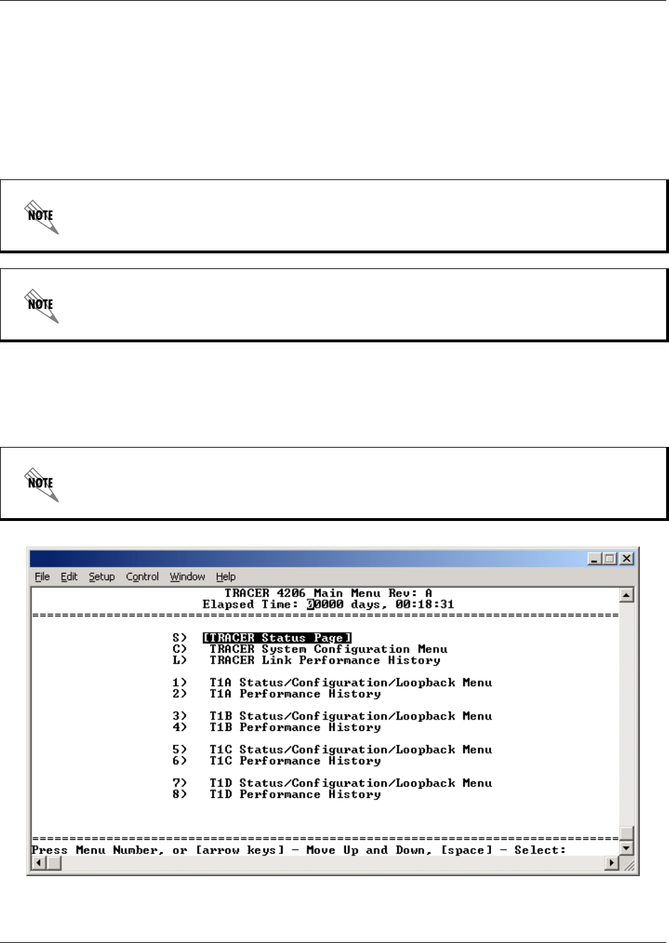
The TRACER 4106/4206 uses 11 (eleven) menu pages and a single main menu page to access its many
features. The main menu page (see Figure 1) provides a link to all available configuration/status pages.
Figure 1. Main Menu Screen
TRACER 4106 and 4206 menu screens are functionally identical, and vary only by
displaying either “TRACER 4106” or “TRACER 4206” on various screens. Only the
TRACER 4206 menus are illustrated in this manual for ease of explanation.
All TRACER 4106/4206 systems are shipped factory default with password protection
disabled.
After connecting a VT100 terminal to the TRACER 4106/4206, press <Ctrl + L> to redraw
the current screen.
Section 5, User Interface Guide TRACER 4206 System Manual
42 © 2002 ADTRAN, Inc. 612804206L1-1B
Navigating using the Keyboard Keys
You can use various keystrokes to move through the terminal menu, to manage a terminal menu session,
and to configure the system.
Moving through the Menus
Session Management Keystrokes
2. TERMINAL MENU AND SYSTEM CONTROL
Password Protection
The TRACER 4106/4206 provides optional password protection of the terminal interface. If enabled, a
password prompt is presented at power-up, reboot, modem logout, or after ten minutes of inactivity on the
terminal. Password protection is enabled and a password is defined via the system configuration menu.
To do this... Press this key...
Move up to select items Up Arrow
Move down to select items Down Arrow
Edit a selected menu item Enter
Scroll through configuration parameters for a menu item Spacebar
Left/Right Arrows
P or N (Prev/Next)
Cancel an edit Escape
Return to Main Menu page M
To do this... Press this key...
Log into a session Spacebar
Refresh the screen
To save time, only the portion of the screen that has changed is refreshed.
<Ctrl + L>
All TRACER 4106/4206 systems are shipped factory default with password protection
disabled.
TRACER 4206 System Manual Section 5, User Interface Guide
612804206L1-1B © 2002 ADTRAN, Inc. 43
3. MENU DESCRIPTIONS
The remainder of this section describes the TRACER 4106/4206 menus and submenus.
>TRACER SYSTEM STATUS
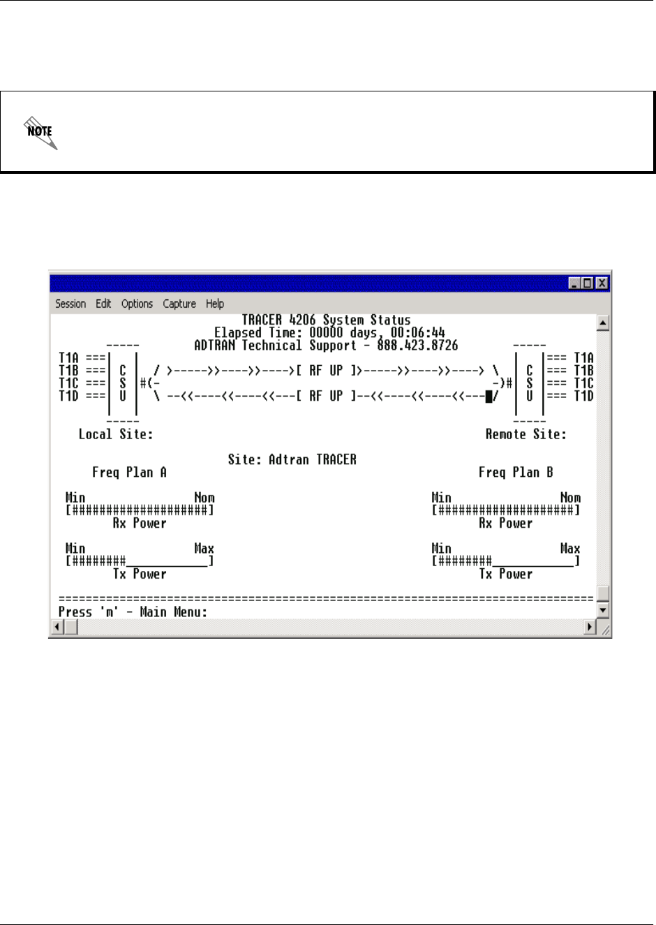
Figure 2 shows the TRACER System Status menu page. Status of major system components for both sides
of the TRACER link are displayed, but no configuration can be performed from this view.
Figure 2. TRACER System Status
The top of the TRACER System Status menu page displays the elapsed time the TRACER 4106/4206
system has been operational since the last power reset. Located directly beneath the ADTRAN Technical
Support phone number is a graphical indicator of the status of the TRACER 4106/4206 T1 and RF links
(as reported by both the local and remote units). The T1 labels will be reverse highlighted if any error
conditions exist on that T1 interface.
The status of the received radio link is indicated as RF UP or RF DOWN for each direction. The left portion
of the menu page reports the status of the local TRACER 4106/4206 (the system where the active terminal
is attached). The right portion of the screen reports the status of the remote system. If the RF link is down,
DATA NOT AVAILABLE will be displayed in place of the remote system status.
The menu structure of the TRACER 4106/4206 system is depicted below as follows:
> MENU PAGE
> MENU PAGE > MENU SELECTION
> MENU PAGE > MENU SELECTION > SUB-MENU

Section 5, User Interface Guide TRACER 4206 System Manual
44 © 2002 ADTRAN, Inc. 612804206L1-1B
To enter the TRACER main menu, press <M>.
>TRACER SYSTEM STATUS > FREQUENCY PLAN
Displays the frequency plan (A or B) for the TRACER 4106/4206 unit. For an operational TRACER
4106/4206 system, the local and remote units should display opposite frequency plans.
>TRACER SYSTEM STATUS > SITE
Displays the site name configured from the TRACER System Configuration page.
>TRACER SYSTEM STATUS > RX POWER
Displays the approximate receiver levels (for both the local and remote units) using a series of symbols (#).
The more symbols (#) displayed, the stronger the signal. If the link is down and remote end data is
unavailable, DATA NOT AVAILABLE is displayed in place of the symbols (#).
>TRACER SYSTEM STATUS > TX POWER
Displays the approximate transmitter levels (for both the local and remote units) using a series of symbols
(#). The more symbols (#) displayed, the stronger the signal. If the link is down and remote end data is
unavailable, DATA NOT AVAILABLE is displayed in place of the symbols (#).
Press <0> from any menu in the TRACER 4106/4206 VT100 menu structure to access the
TRACER System Status page.
TRACER 4206 System Manual Section 5, User Interface Guide
612804206L1-1B © 2002 ADTRAN, Inc. 45
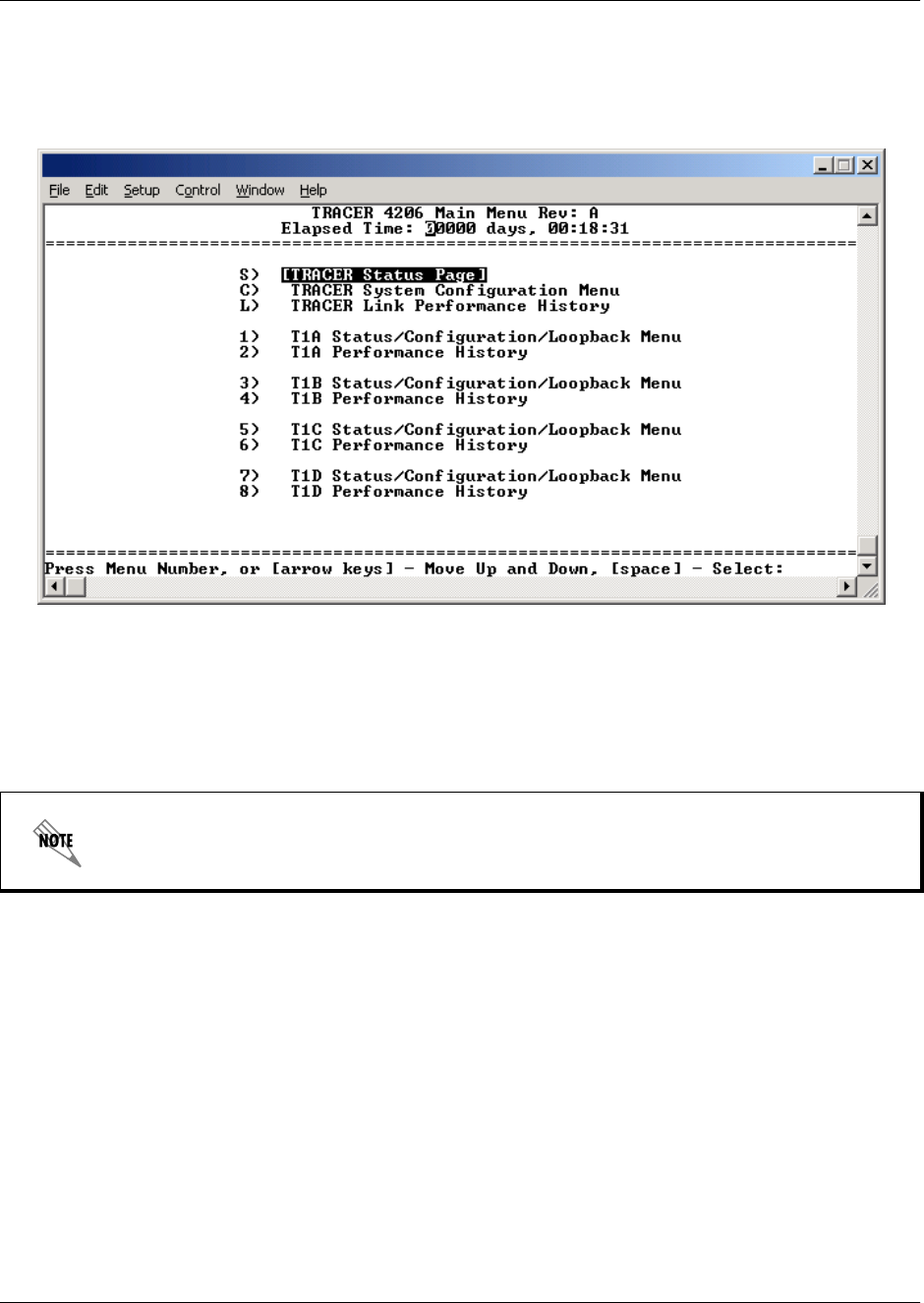
>MAIN MENU
The TRACER 4106/4206 Main Menu page provides access to all other configuration/status pages.
Figure 3 shows the TRACER Main Menu page.
Figure 3. Main Menu
Use the up and down arrow keys to scroll through the available pages, or enter the number or letter of the
selected page (to highlight the menu page) and press <Enter>.
Press <M> from any menu in the TRACER 4106/4206 VT100 menu structure to access the
TRACER Main Menu page.
Section 5, User Interface Guide TRACER 4206 System Manual
46 © 2002 ADTRAN, Inc. 612804206L1-1B
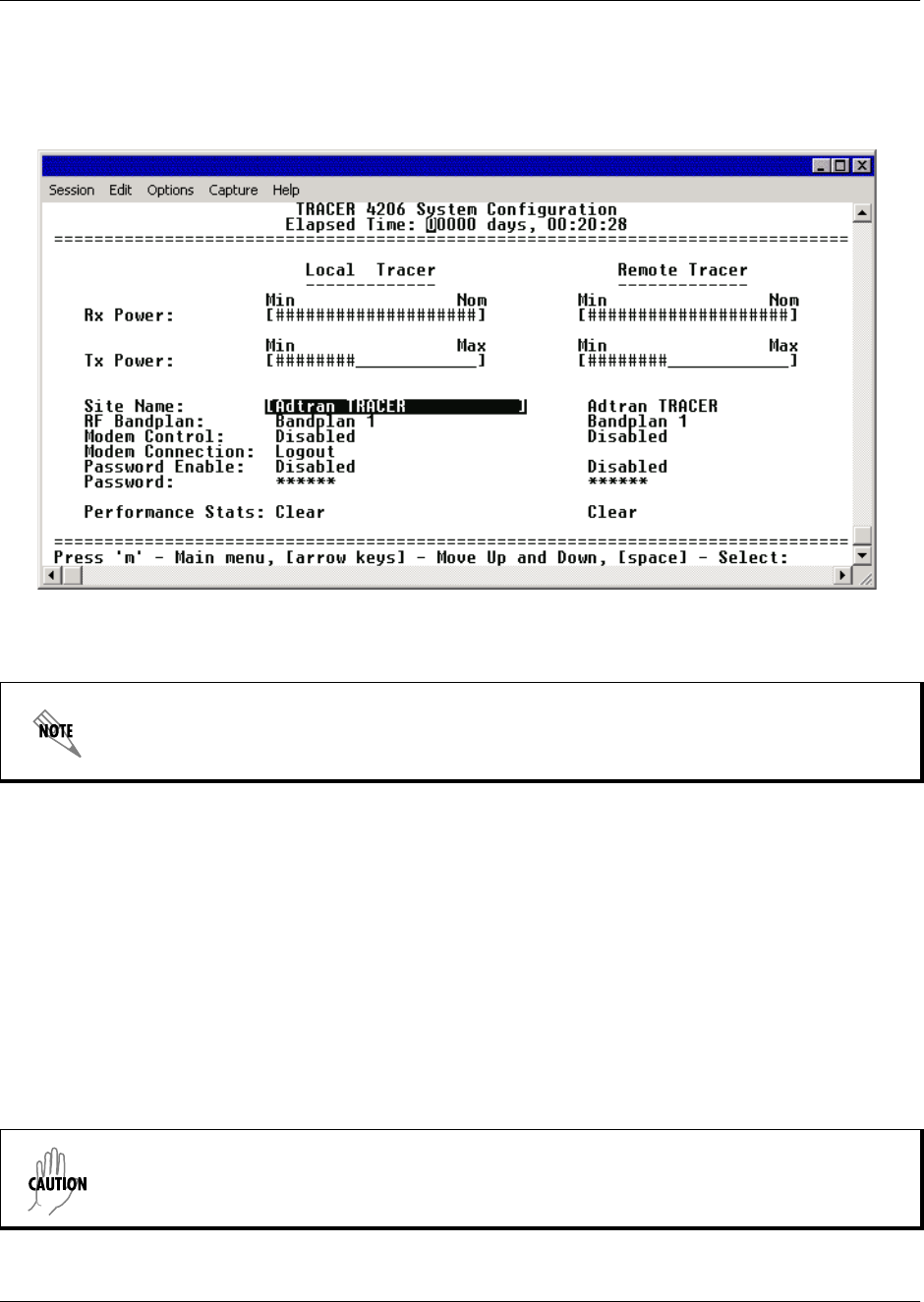
>TRACER SYSTEM CONFIGURATION
Figure 4 shows the TRACER System Configuration menu page. System configuration parameters for both
the local and remote TRACER 4106/4206 units are available through this menu page.
Figure 4. TRACER System Configuration
>TRACER SYSTEM CONFIGURATION > RX POWER
Displays the approximate receiver levels (for both the local and remote units) using a series of symbols (#).
The more symbols (#) displayed, the stronger the signal. If the link is down and remote end data is
unavailable, DATA NOT AVAILABLE is displayed in place of the symbols (#). This parameter is display only.
>TRACER SYSTEM CONFIGURATION > TX POWER
Allows the transmitter levels (for both the local and remote units) to be adjusted. The current transmitter
level is displayed using a series of symbols (#). The more symbols (#) displayed, the stronger the signal. If
the link is down and remote end data is unavailable, DATA NOT AVAILABLE is displayed in place of the
symbols (#).
Press <C> from any menu in the TRACER 4106/4206 VT100 menu structure to access the
TRACER System Configuration menu page.
Reducing the transmitter power of the remote TRACER 4106/4206 could negatively impact
the TRACER RF link.
TRACER 4206 System Manual Section 5, User Interface Guide
612804206L1-1B © 2002 ADTRAN, Inc. 47
>TRACER SYSTEM CONFIGURATION > SITE NAME
Enter up to 25 alphanumeric characters to be displayed for identification of the TRACER 4106/4206
system.
>TRACER SYSTEM CONFIGURATION > RF BANDPLAN
Sets the bandplan for the TRACER 4106/4206. Each channel is divided into three bandplans (1, 2, or 3).
Both local and remote TRACER 4106/4206 must be configured with the same bandplan (1, 2, or 3) but
different channel plans (Plan A or Plan B). For example, the transmitter at one end of the link will transmit
in bandplan 1 of channel A (the lower portion of the spectrum) and receive in bandplan 1 of channel B (the
upper portion). Consequently, the receiver at the other end should receive in bandplan 1 of channel A (the
lower portion) and transmit in bandplan 1 of channel B (the upper portion). (Refer to Figure 5 and Figure
6.). The TRACER 4106/4206 comes factory programmed with RF bandplan set to Band 1.
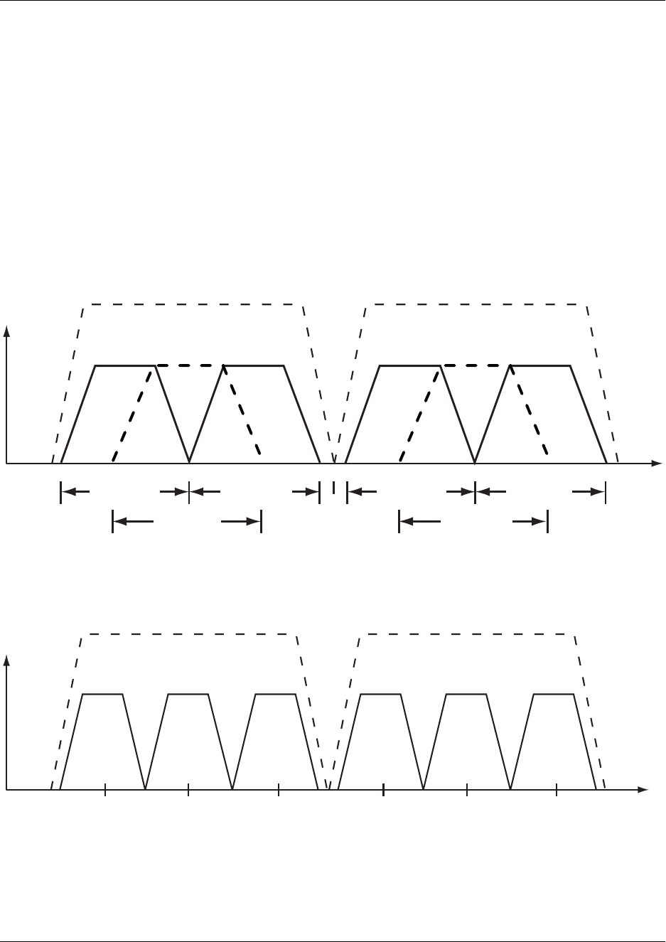
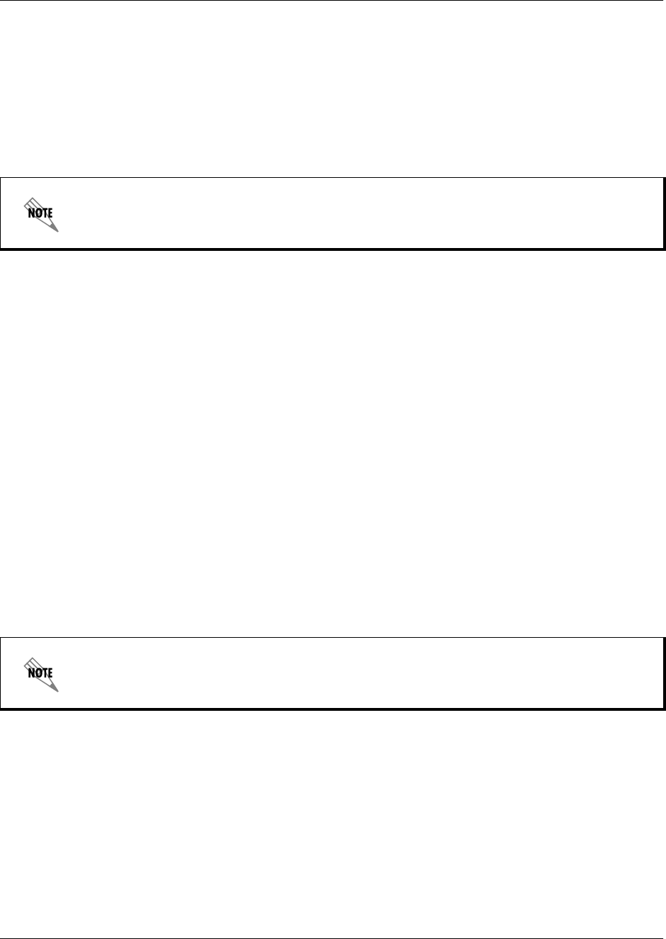
Figure 5. 2.4 GHz Bandwidth Division (TRACER 4106)
Figure 6. 5.8 GHz Bandwidth Division (TRACER 4206)
Channel A
2416 2441.752422 24282400 MHz 2483.5 MHz
Bandplan 3
Bandplan 2
Bandplan 1
Channel B
2456 2462 2468
Bandplan 3
Bandplan 2
Bandplan 1
Channel A
57345725 5787 58505744 5753MHz MHz
Bandplan 3Bandplan 2Bandplan 1
Channel B
5814 5824 5833
Bandplan 3Bandplan 2Bandplan 1
Section 5, User Interface Guide TRACER 4206 System Manual
48 © 2002 ADTRAN, Inc. 612804206L1-1B
>TRACER SYSTEM CONFIGURATION > MODEM CONTROL
Configures the modem control leads on the RS-232 port (terminal interface located on the rear panel of the
unit). Set MODEM CONTROL to ENABLED when connecting the unit to a modem (using a null modem
adapter). Setting MODEM CONTROL to DISABLED prevents the TRACER 4106/4206 from monitoring DCD
and enables data to be sent to the VT 100 continuously. MODEM CONTROL must be set to DISABLED when the
VT100 terminal is in use. The TRACER 4106/4206 comes factory programmed with MODEM CONTROL set
to DISABLED.
>TRACER SYSTEM CONFIGURATION > MODEM CONNECTION (LOGOUT)
Activator to cause the TRACER 4106/4206 to de-assert Clear To Send (CTS) and DSR for a time greater
than 20 milliseconds. This signals the modem to disconnect the analog connection. Hangup-On-DTR-Drop
may need to be explicitly enabled on some modems. If PASSWORD PROTECTION is ENABLED, this menu also
causes the unit to close the current session and return to the TRACER System Status menu page and wait
for password input.
>TRACER SYSTEM CONFIGURATION > PASSWORD ENABLE
Configures password protection for the VT100 terminal interface. Password protection for the TRACER
4106/4206 requires password input from the TRACER System Status menu page when connecting to the
unit. When configured for Password protection, the TRACER 4106/4206 closes any terminal session that
remains inactive for more than 10 minutes. The TRACER 4106/4206 comes factory programmed with
PASSWORD ENABLE set to DISABLED.
>TRACER SYSTEM CONFIGURATION > PASSWORD
Sets the password for password protection of the TRACER 4106/4206 VT100 terminal interface. Enter up
to 8 alphanumeric characters. The system password is case sensitive.
>TRACER SYSTEM CONFIGURATION > PERFORMANCE STATS (CLEAR)
Activator to reset all system error counters for the TRACER 4106/4206.
Press <Ctrl+Z> three times from the terminal interface to temporarily disable MODEM
CONTROL when the modem control leads are active.
The default password for the TRACER 4106/4206 is tracer.
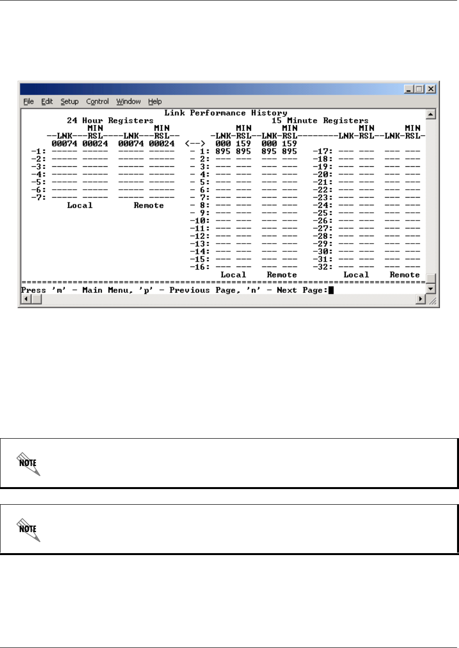
TRACER 4206 System Manual Section 5, User Interface Guide
612804206L1-1B © 2002 ADTRAN, Inc. 49
>TRACER LINK PERFORMANCE HISTORY
Figure 7 shows the TRACER Link Performance History menu page. The TRACER Link Performance
History menu page displays detailed error statistics and received signal level for the RF link (from both the
local and remote TRACER 4106/4206 units) in 15-minute increments.
Figure 7. TRACER Link Performance History
The minimum received signal level (MIN RSL) is represented as a numerical value from 0 to 255 with 0
corresponding to no receive power and 255 corresponding to an extremely strong signal. The minimum
received signal level is directly related to RSSI.
The error count and received signal level for the most recent 24 hours are recorded and displayed on the
right side of the page. The left side of the page displays the 24 hour totals for the most recent 7 days.
Press <N> to view the next 8 hours worth of 15-minute totals and <P> to view the
previous 8 hours.
Press <L> from any menu in the TRACER 4106/4206 VT100 menu structure to access the
TRACER Link Performance History menu page.
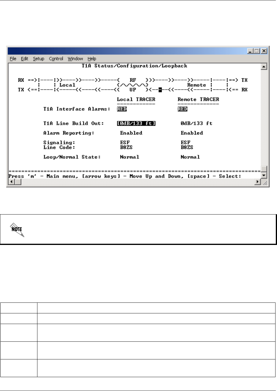
Section 5, User Interface Guide TRACER 4206 System Manual
50 © 2002 ADTRAN, Inc. 612804206L1-1B
>T1A STATUS/CONFIGURATION/LOOPBACK
Figure 8 shows the T1A Status/Configuration/Loopback menu page. Real-time graphical representation
for the T1A link (using data from both the local and remote TRACER 4106/4206 units) is displayed on this
page. T1A operational configuration parameters and testing functions are configured from this menu.
Figure 8. T1A Status/Configuration/Loopback
>T1A STATUS/CONFIGURATION/LOOPBACK > T1A INTERFACE ALARMS
Displays any active alarms on the T1A link (reported from both the local and remote TRACER 4106/4206
units). These alarms include Red, Blue, Yellow, AIS, and bipolar violations (BPV). See Section 6,
Troubleshooting Guide, for more information on these alarms.
Press <1> from any menu in the TRACER 4106/4206 VT100 menu structure to access the
T1A Status/Configuration/Loopback menu page.
Table 1. T1 Interface Alarms
RED Activates when a local facility failure occurs.
BPV Activates when the incoming T1 stream presents bipolar violations (BPVs).
AIS Activates when an incoming remote alarm is received from a connected T1 device. An AIS
signal is an unframed All One signal that replaces the normal traffic signal
YEL Activates when an incoming remote alarm is received from the T1 device indicating that a
failure has occurred in the received direction.
LOS Activates when no T1 signal is present from the connected T1 equipment. LOS is
activated after receiving 192 consecutive zeros.
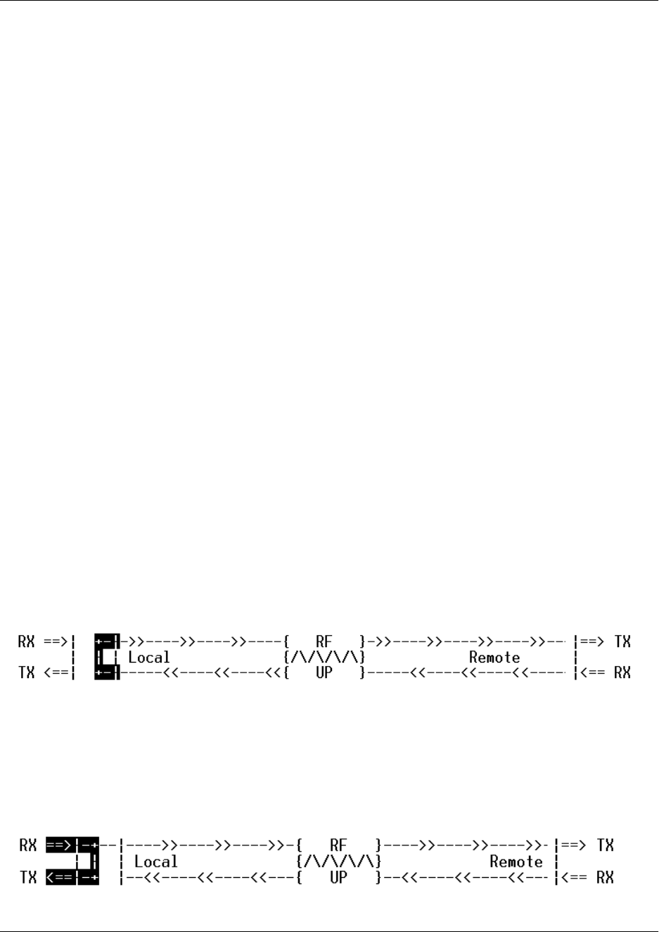
TRACER 4206 System Manual Section 5, User Interface Guide
612804206L1-1B © 2002 ADTRAN, Inc. 51
>T1A STATUS/CONFIGURATION/LOOPBACK > T1A LINE BUILD OUT
Configures the T1A for the appropriate line buildout, based on the distance to the T1A equipment.
>T1A STATUS/CONFIGURATION/LOOPBACK > ALARM REPORTING
Determines whether the TRACER 4106/4206 unit will report active alarms. If DISABLED, no alarms will be
displayed on this menu page. The ALARM REPORTING parameter is independently configured for the local
and remote TRACER 4106/4206 units. When DISABLED, the front panel LED alarms will also be disabled
(OFF).
>T1A STATUS/CONFIGURATION/LOOPBACK > SIGNALING
Configures the framing format for the T1A link for both the local and remote TRACER 4106/4206 units.
The TRACER 4106/4206 transports T1A data across the link (as long as the T1A signal is properly timed).
Configure the framing format (using the SIGNALING menu) to enable the TRACER 4106/4206 to monitor
incoming framing error events and indicate problems with the attached metallic service. The TRACER
4106/4206 supports both ESF and D4 framing formats.
>T1A STATUS/CONFIGURATION/LOOPBACK > LINE CODE
Sets the line coding for the T1A link. The TRACER 4106/4206 supports B8ZS and AMI line coding.
>T1A STATUS/CONFIGURATION/LOOPBACK > LOOP/NORMAL STATE
Controls the loop status of the T1A link. Activates/deactivates loopback conditions for testing purposes.
>T1A STATUS/CONFIGURATION/LOOPBACK > LOOP/NORMAL STATE > NORMAL
The T1A link is in normal data transport mode - there are no active loopbacks.
>T1A STATUS/CONFIGURATION/LOOPBACK > LOOP/NORMAL STATE > LINK
Activates a loopback at the TRACER 4106/4206 T1A framer towards the wireless link (see Figure 9). Use
the LINK loopback to test data path integrity from one unit across the wireless link.
Figure 9. T1A Link Loopback
>T1A STATUS/CONFIGURATION/LOOPBACK > LOOP/NORMAL STATE > LINE
Activates a loopback at the TRACER 4106/4206 T1A framer towards the locally connected T1A
equipment (see Figure 10). Use the LINE loopback to test data path integrity from the TRACER 4106/4206
unit to the T1A equipment.
Figure 10. T1A Line Loopback
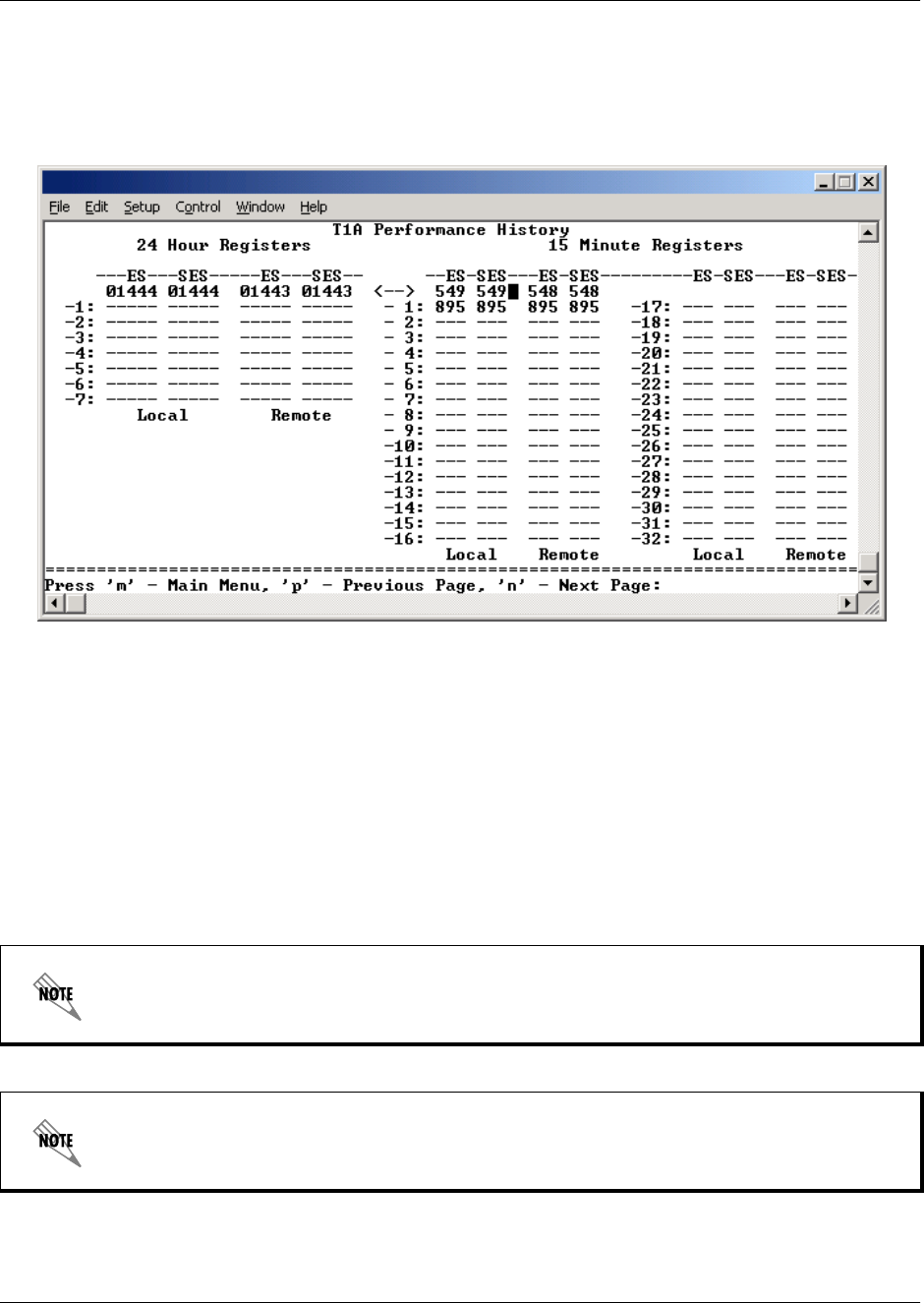
Section 5, User Interface Guide TRACER 4206 System Manual
52 © 2002 ADTRAN, Inc. 612804206L1-1B
>T1A PERFORMANCE HISTORY
Figure 11 shows the T1A Performance History menu page. The T1A Performance History menu page
displays detailed error statistics for the T1A link (from both the local and remote TRACER 4106/4206
units) in 15-minute increments.
Figure 11. T1A Link Performance History
T1A performance data is presented as Errored Seconds (ES) and Severely Errored Seconds (SES) on the
T1A link. The following events qualify as an ES–AIS, LOS or LOF Alarm Second, a single BPV or
excessive zero event, or a single parity bit. An SES is caused by an AIS, LOS or LOF Alarm Second, or
excessive Bipolar Violations (BPVs) or framed Parity Bit errors causing a line Bit Error Rate (BER) of
10-6.
The error count for the most recent 24 hours are recorded and displayed on the right side of the page. The
left side of the page displays the 24 hour totals for the most recent 7 days.
Press <N> to view the next 8 hours worth of 15-minute totals and <P> to view the
previous 8 hours.
Press <2> from any menu in the TRACER 4106/4206 VT100 menu structure to access the
T1A Link Performance History menu page.
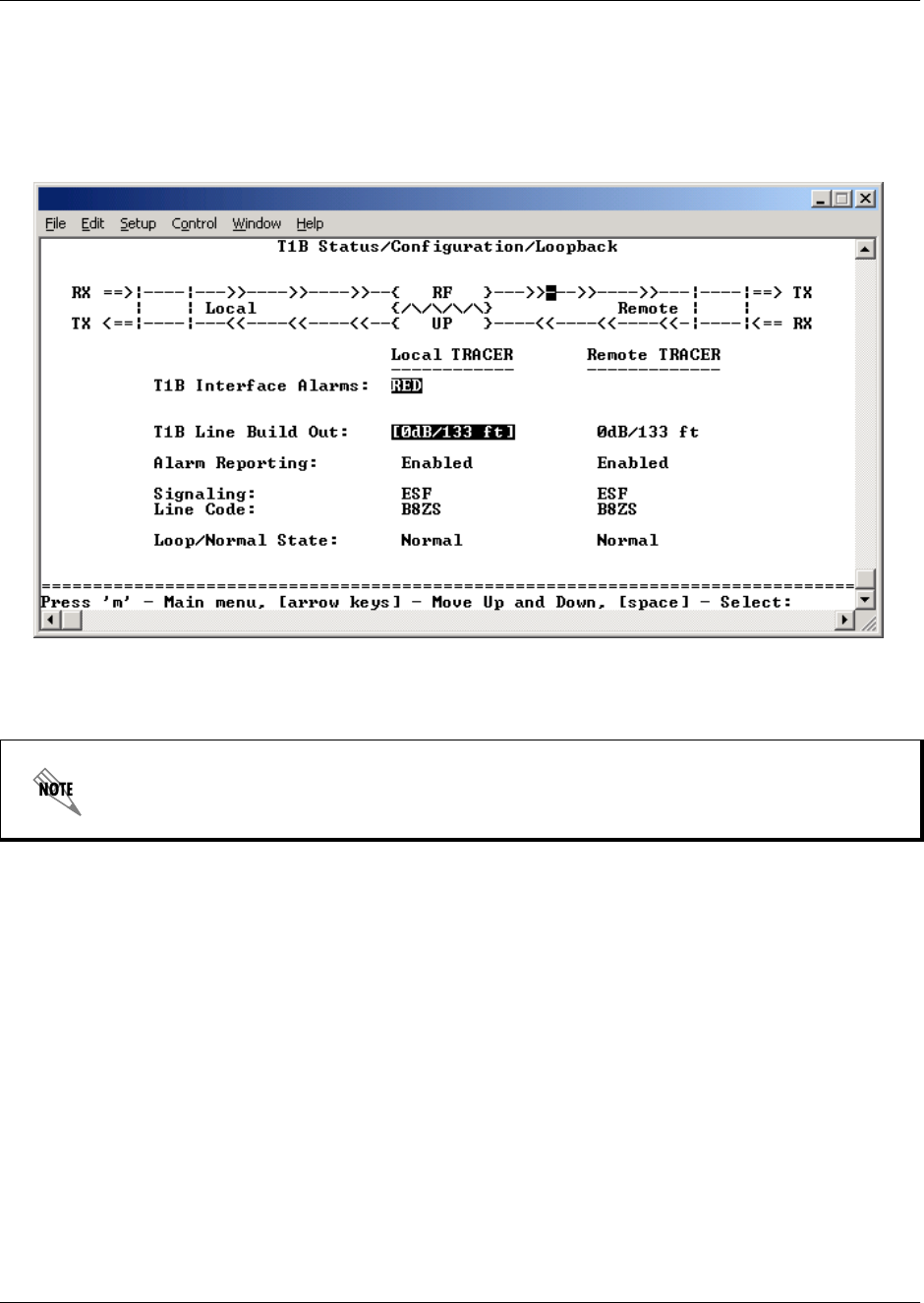
TRACER 4206 System Manual Section 5, User Interface Guide
612804206L1-1B © 2002 ADTRAN, Inc. 53
>T1B STATUS/CONFIGURATION/LOOPBACK
Figure 12 shows the T1B Status/Configuration/Loopback menu page. Real-time graphical representation
for the T1B link (using data from both the local and remote TRACER 4106/4206 units) is displayed on this
page. T1B operational configuration parameters and testing functions are configured from this menu.
Figure 12. T1B Status/Configuration/Loopback
>T1B STATUS/CONFIGURATION/LOOPBACK > T1B INTERFACE ALARMS
Displays active alarms on the T1B link reported from both the local and remote TRACER 4106/4206 units.
These alarms include Red, Blue, Yellow, AIS, and bipolar violations (BPV). See Tabl e 1 on page 50 for
more information on these alarms.
>T1B STATUS/CONFIGURATION/LOOPBACK > T1B LINE BUILD OUT
Configures the T1B for the appropriate line buildout, based on the distance to the T1B equipment.
>T1B STATUS/CONFIGURATION/LOOPBACK > ALARM REPORTING
Determines whether the TRACER 4106/4206 unit will report active alarms. If DISABLED, no alarms will
be displayed on this menu page. The Alarm Reporting parameter is independently configured for local and
remote TRACER 4106/4206 units. When DISABLED, the front panel LED alarms will also be disabled (off).
Press <3> from any menu in the TRACER 4106/4206 VT100 menu structure to access the
T1B Status/Configuration/Loopback menu page.
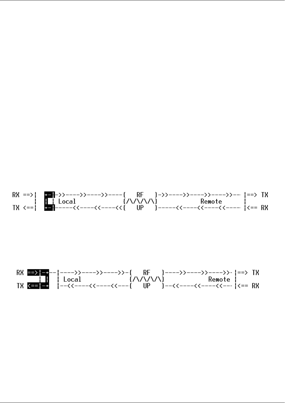
Section 5, User Interface Guide TRACER 4206 System Manual
54 © 2002 ADTRAN, Inc. 612804206L1-1B
>T1B STATUS/CONFIGURATION/LOOPBACK > SIGNALING
Configure the framing format for the T1B link for both the local and remote TRACER 4106/4206 units.
The TRACER 4106/4206 transports T1B data across the link (as long as the T1B signal is properly timed).
Configure the framing format (using the SIGNALING menu) to enable the TRACER 4106/4206 to monitor
the incoming framing error events and indicate problems with the attached metallic service. The TRACER
4106/4206 supports both ESF and D4 framing formats.
>T1B STATUS/CONFIGURATION/LOOPBACK > LINE CODE
Sets the line coding for the T1B link. The TRACER 4106/4206 supports B8ZS and AMI line coding.
>T1B STATUS/CONFIGURATION/LOOPBACK > LOOP/NORMAL STATE
Controls the loop status of the T1B link. Activates/deactivates loopback conditions for testing purposes.
>T1B STATUS/CONFIGURATION/LOOPBACK >LOOP/NORMAL STATE > NORMAL
The T1B link is in normal data transport mode - there are no active loopbacks.
>T1B STATUS/CONFIGURATION/LOOPBACK >LOOP/NORMAL STATE > LINK
Activates a loopback at the TRACER 4106/4206 T1B framer towards the wireless link (see Figure 13).
Use the LINK loopback to test data path integrity from one unit across the wireless link.
Figure 13. T1B Link Loopback
>T1B STATUS/CONFIGURATION/LOOPBACK >LOOP/NORMAL STATE > LINE
Activates a loopback at the TRACER 4106/4206 T1B framer towards the wireless link (see Figure 14).
Use the LINE loopback to test data path integrity from the TRACER 4106/4206 unit to the T1 equipment.
Figure 14. T1B Line Loopback
>T1B PERFORMANCE HISTORY
Figure 15 shows the T1B Performance History menu page. The T1B Performance History menu page
displays detailed error statistics for the T1B link (from both the local and remote TRACER 4106/4206
units) in 15 minute increments.
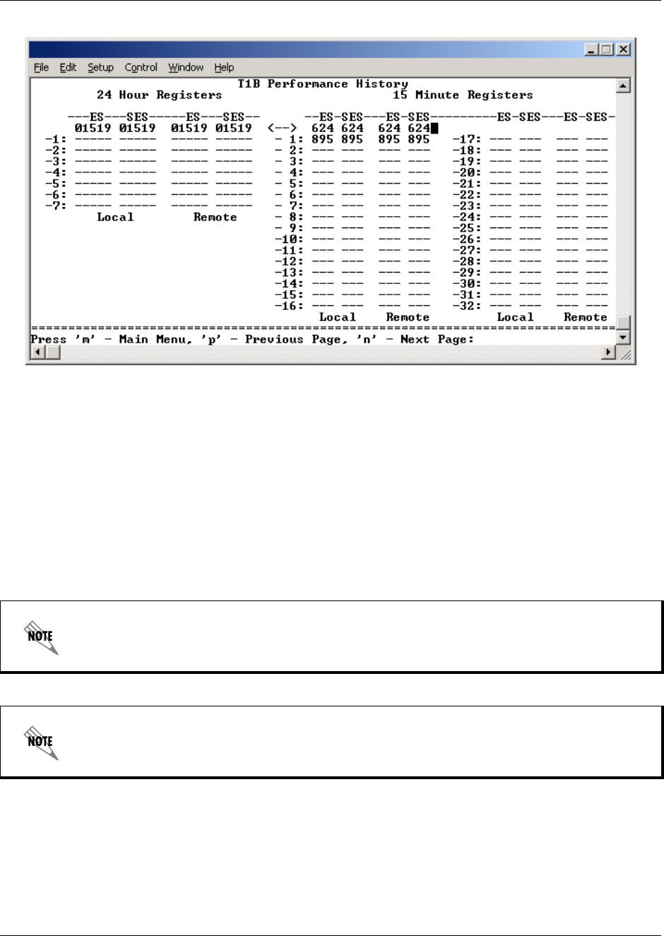
TRACER 4206 System Manual Section 5, User Interface Guide
612804206L1-1B © 2002 ADTRAN, Inc. 55
Figure 15. T1B Link Performance History
T1B performance data is presented as Errored Seconds (ES) and Severely Errored Seconds (SES) on the
T1B link. The following events qualify as an ES–AIS, LOS or LOF Alarm Second, a single BPV or
excessive zero event, or a single parity bit. An SES is caused by an AIS, LOS or LOF Alarm Second, or
excessive Bipolar Violations (BPVs) or framed Parity Bit errors causing a line Bit Error Rate (BER) of
10-6.
The error count for the most recent 24 hours are recorded and displayed on the right side of the page. The
left side of the page displays the 24 hour totals for the most recent 7 days.
>T1C STATUS/CONFIGURATION/LOOPBACK
Figure 16 shows the T1C Status/Configuration/Loopback menu page. Real-time graphical representation
for the T1C link using data from both the local and remote TRACER 4106/4206 units) is displayed on this
page. T1C operational configuration parameters and testing functions are configured from this menu.
Press <N> to view the next 8 hours worth of 15 minute totals and <P> to view the
previous 8 hours.
Press <4> from any menu in the TRACER 4106/4206 VT100 menu structure to access the
T1B Link Performance History page.
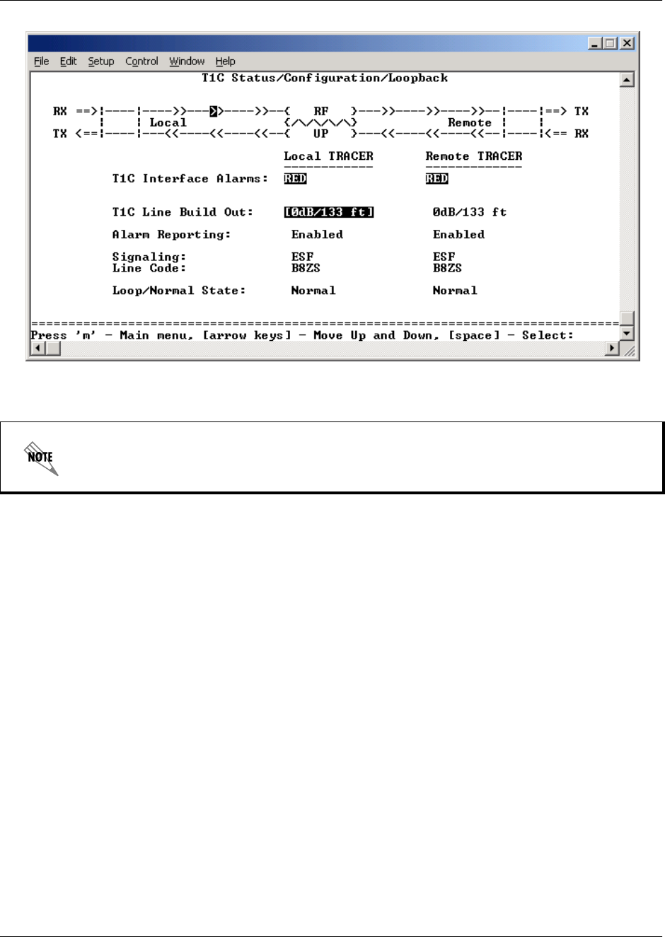
Section 5, User Interface Guide TRACER 4206 System Manual
56 © 2002 ADTRAN, Inc. 612804206L1-1B
Figure 16. T1C Status/Configuration/Loopback
>T1C STATUS/CONFIGURATION/LOOPBACK > T1C INTERFACE ALARMS
Displays and active alarms on the T1C link reported from both the local and remote TRACER 4106/4206
units. These alarms include Red, Blue, Yellow, AIS, and bipolar violations (BPV). See Table 1 on page
50, for more information on these alarms.
>T1C STATUS/CONFIGURATION/LOOPBACK > T1C LINE BUILD OUT
Configures the T1C for the appropriate line buildout, based on the distance to the T1C equipment.
>T1C STATUS/CONFIGURATION/LOOPBACK > ALARM REPORTING
Determines whether the TRACER 4106/4206 unit will report active alarms. If DISABLED, no alarms will
be displayed on this menu page. The Alarm Reporting parameter is independently configured for local and
remote TRACER 4106/4206 units. When DISABLED, the front panel LED alarms will also be disabled (off).
>T1C STATUS/CONFIGURATION/LOOPBACK > SIGNALING
Configure the framing format for the T1C link for both the local and remote TRACER 4106/4206 units.
The TRACER 4106/4206 transports T1C data across the link (as long as the T1C signal is properly timed).
Configure the framing format (using the SIGNALING menu) to enable the TRACER 4106/4206 to monitor
the incoming framing error events and indicate problems with the attached metallic service. The TRACER
4106/4206 supports both ESF and D4 framing formats.
Press <5> from any menu in the TRACER 4106/4206 VT100 menu structure to access the
T1C Status/Configuration/Loopback menu page.
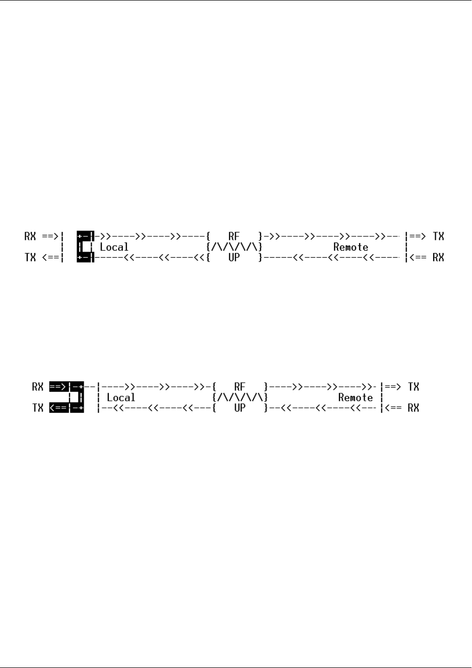
TRACER 4206 System Manual Section 5, User Interface Guide
612804206L1-1B © 2002 ADTRAN, Inc. 57
>T1C STATUS/CONFIGURATION/LOOPBACK > LINE CODE
Sets the line coding for the T1C link. The TRACER 4106/4206 supports B8ZS and AMI line coding.
>T1C STATUS/CONFIGURATION/LOOPBACK > LOOP/NORMAL STATE
Controls the loop status of the T1C link. Activates/deactivates loopback conditions for testing purposes.
>T1C STATUS/CONFIGURATION/LOOPBACK > LOOP/NORMAL STATE > NORMAL
The T1C link is in normal data transport mode - there are no active loopbacks.
>T1C STATUS/CONFIGURATION/LOOPBACK > LOOP/NORMAL STATE > LINK
Activates a loopback at the TRACER 4106/4206 T1C framer towards the wireless link (see Figure 17).
Use the LINK loopback to test data path integrity from one unit across the wireless link.
Figure 17. T1C Link Loopback
>T1C STATUS/CONFIGURATION/LOOPBACK > LOOP/NORMAL STATE > LINE
Activates a loopback at the TRACER 4106/4206 T1C framer towards the wireless link (see Figure 18).
Use the LINE loopback to test data path integrity from the TRACER 4106/4206 unit to the T1 equipment.
Figure 18. T1C Line Loopback

Section 5, User Interface Guide TRACER 4206 System Manual
58 © 2002 ADTRAN, Inc. 612804206L1-1B
>T1C PERFORMANCE HISTORY
Figure 19 shows the T1C Performance History menu page. The T1C Performance History menu page
displays detailed error statistics for the T1C link (from both the local and remote TRACER 4106/4206
units) in 15 minute increments.
Figure 19. T1C Performance History
T1C performance data is presented as Errored Seconds (ES) and Severely Errored Seconds (SES) on the
T1C link. The following events qualify as an ES–AIS, LOS or LOF Alarm Second, a single BPV or
excessive zero event, or a single parity bit. An SES is caused by an AIS, LOS or LOF Alarm Second, or
excessive Bipolar Violations (BPVs) or framed Parity Bit errors causing a line Bit Error Rate (BER) of
10-6.
The error count for the most recent 24 hours are recorded and displayed on the right side of the page. The
left side of the page displays the 24 hour totals for the most recent 7 days.
Press <N> to view the next 8 hours worth of 15 minute totals and <P> to view the
previous 8 hours.
Press <6> from any menu in the TRACER 4106/4206 VT100 menu structure to access the
T1C Link Performance History page.

TRACER 4206 System Manual Section 5, User Interface Guide
612804206L1-1B © 2002 ADTRAN, Inc. 59
>T1D STATUS/CONFIGURATION/LOOPBACK
Figure 20 shows the T1D Status/Configuration/Loopback menu page. Real-time graphical representation
for the T1D link (using data from both the local and remote TRACER 4106/4206 units) is displayed on this
page. T1D operational configuration parameters and testing functions are configured from this menu.
Figure 20. T1D Status/Configuration/Loopback
>T1D STATUS/CONFIGURATION/LOOPBACK > T1D INTERFACE ALARMS
Displays and active alarms on the T1D link reported from both the local and remote TRACER 4106/4206
units. These alarms include Red, Blue, Yellow, AIS, and bipolar violations (BPV). See Table 1 on page
50, for more information on these alarms.
>T1D STATUS/CONFIGURATION/LOOPBACK > T1D LINE BUILD OUT
Configures the T1D for the appropriate line buildout, based on the distance to the T1D equipment.
>T1D STATUS/CONFIGURATION/LOOPBACK > ALARM REPORTING
Determines whether the TRACER 4106/4206 unit will report active alarms. If DISABLED, no alarms will
be displayed on this menu page. The Alarm Reporting parameter is independently configured for local and
remote TRACER 4106/4206 units. When DISABLED, the front panel LED alarms will also be disabled (off).
Press <7> from any menu in the TRACER 4106/4206 VT100 menu structure to access the
T1D Status/Configuration/Loopback menu page.
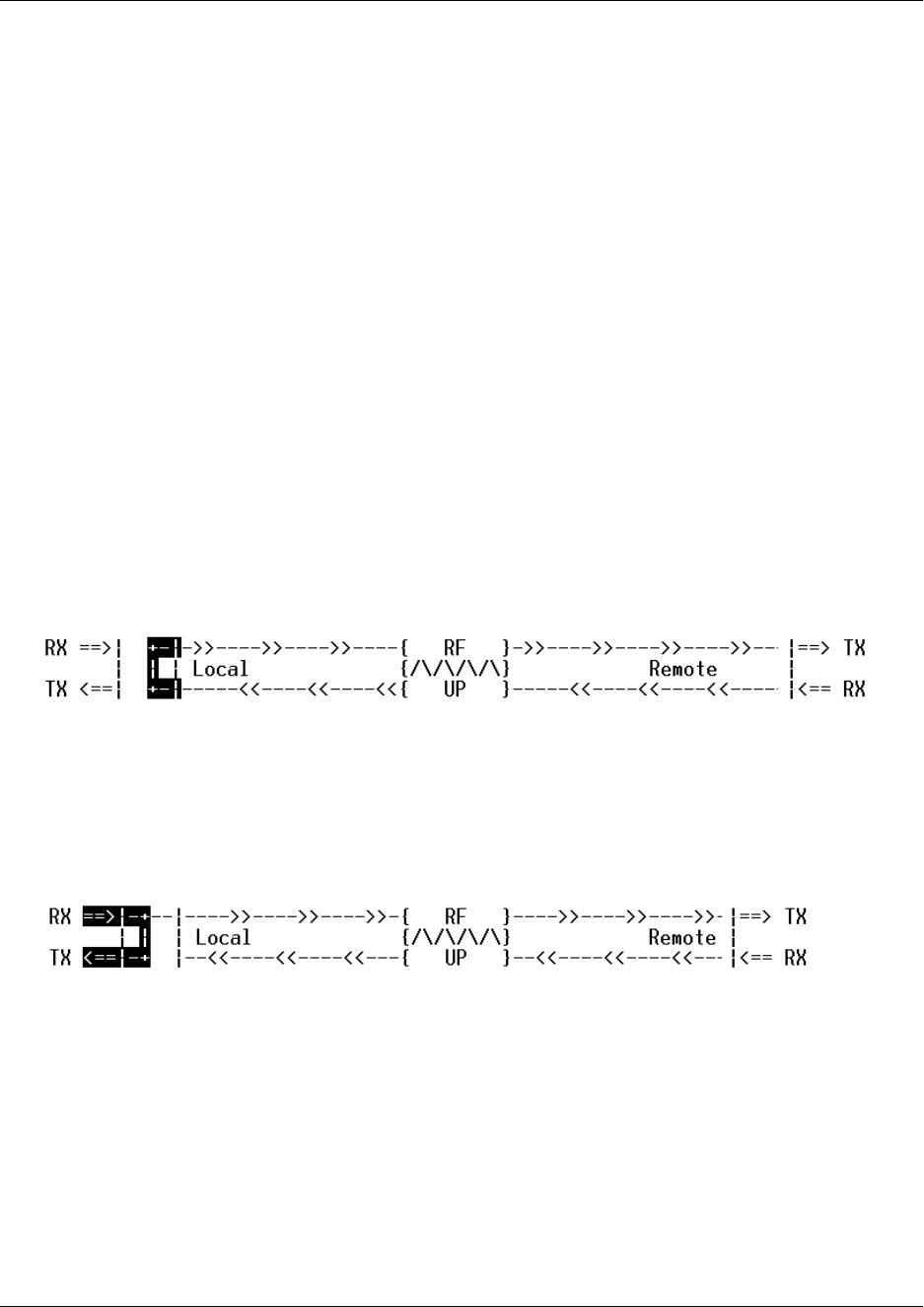
Section 5, User Interface Guide TRACER 4206 System Manual
60 © 2002 ADTRAN, Inc. 612804206L1-1B
>T1D STATUS/CONFIGURATION/LOOPBACK > SIGNALING
Configure the framing format for the T1D link for both the local and remote TRACER 4106/4206 units.
The TRACER 4106/4206 transports T1D data across the link (as long as the T1D signal is properly timed).
Configure the framing format (using the SIGNALING menu) to enable the TRACER 4106/4206 to monitor
the incoming framing error events and indicate problems with the attached metallic service. The TRACER
4106/4206 supports both ESF and D4 framing formats.
>T1D STATUS/CONFIGURATION/LOOPBACK > LINE CODE
Sets the line coding for the T1D link. The TRACER 4106/4206 supports B8ZS and AMI line coding.
>T1D STATUS/CONFIGURATION/LOOPBACK > LOOP/NORMAL STATE
Controls the loop status of the T1D link. Activates/deactivates loopback conditions for testing purposes.
>T1D STATUS/CONFIGURATION/LOOPBACK > LOOP/NORMAL STATE > NORMAL
The T1D link is in normal data transport mode - there are no active loopbacks.
>T1D STATUS/CONFIGURATION/LOOPBACK > LOOP/NORMAL STATE > LINK
Activates a loopback at the TRACER 4106/4206 T1D framer towards the wireless link (see Figure 21).
Use the LINK loopback to test data path integrity from one unit across the wireless link.
Figure 21. T1D Link Loopback
>T1D STATUS/CONFIGURATION/LOOPBACK > LOOP/NORMAL STATE > LINE
Activates a loopback at the TRACER 4106/4206 T1D framer towards the wireless link (see Figure 22).
Use the LINE loopback to test data path integrity from the TRACER 4106/4206 unit to the T1 equipment.
Figure 22. T1D Line Loopback
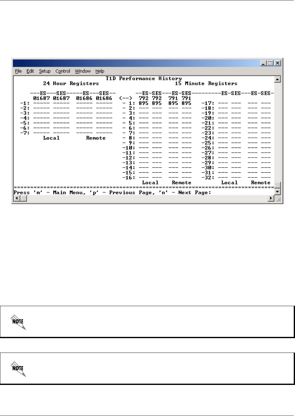
TRACER 4206 System Manual Section 5, User Interface Guide
612804206L1-1B © 2002 ADTRAN, Inc. 61
>T1D PERFORMANCE HISTORY
Figure 23 shows the T1D Performance History menu page. The T1D Performance History menu page
displays detailed error statistics for the T1D link (from both the local and remote TRACER 4106/4206
units) in 15 minute increments.
Figure 23. T1D Performance History
T1D performance data is presented as Errored Seconds (ES) and Severely Errored Seconds (SES) on the
T1D link. The following events qualify as an ES–AIS, LOS or LOF Alarm Second, a single BPV or
excessive zero event, or a single parity bit. An SES is caused by an AIS, LOS or LOF Alarm Second, or
excessive Bipolar Violations (BPVs) or framed Parity Bit errors causing a line Bit Error Rate (BER) of
10-6.
The error count for the most recent 24 hours are recorded and displayed on the right side of the page. The
left side of the page displays the 24 hour totals for the most recent 7 days.
Press <N> to view the next 8 hours worth of 15 minute totals and <P> to view the
previous 8 hours.
Press <8> from any menu in the TRACER 4106/4206 VT100 menu structure to access the
T1D Link Performance History page.

Section 5, User Interface Guide TRACER 4206 System Manual
62 © 2002 ADTRAN, Inc. 612804206L1-1B

612804206L1-1B © 2002 ADTRAN, Inc. 61
TROUBLESHOOTING GUIDE
CONTENTS
Overview. . . . . . . . . . . . . . . . . . . . . . . . . . . . . . . . . . . . . . . . . . . . . . . . . . . . . . . . . . . . . . . . . . . . . . . 62
LED Indicators . . . . . . . . . . . . . . . . . . . . . . . . . . . . . . . . . . . . . . . . . . . . . . . . . . . . . . . . . . . . . . . . . . 62
PWR LED . . . . . . . . . . . . . . . . . . . . . . . . . . . . . . . . . . . . . . . . . . . . . . . . . . . . . . . . . . . . . . . . . . . 62
TST LED . . . . . . . . . . . . . . . . . . . . . . . . . . . . . . . . . . . . . . . . . . . . . . . . . . . . . . . . . . . . . . . . . . . . 62
RF DOWN LED . . . . . . . . . . . . . . . . . . . . . . . . . . . . . . . . . . . . . . . . . . . . . . . . . . . . . . . . . . . . . . . 62
RF LOW LED . . . . . . . . . . . . . . . . . . . . . . . . . . . . . . . . . . . . . . . . . . . . . . . . . . . . . . . . . . . . . . . . 63
T1 Alarm LEDs . . . . . . . . . . . . . . . . . . . . . . . . . . . . . . . . . . . . . . . . . . . . . . . . . . . . . . . . . . . . . . . 63
RF Errors . . . . . . . . . . . . . . . . . . . . . . . . . . . . . . . . . . . . . . . . . . . . . . . . . . . . . . . . . . . . . . . . . . . . . . 64
Step-by-Step Troubleshooting . . . . . . . . . . . . . . . . . . . . . . . . . . . . . . . . . . . . . . . . . . . . . . . . . . . . . 64
Installing/Troubleshooting the TRACER Hardware . . . . . . . . . . . . . . . . . . . . . . . . . . . . . . . . . . . . 64
Installing/Configuring T1 Hardware. . . . . . . . . . . . . . . . . . . . . . . . . . . . . . . . . . . . . . . . . . . . . . . .66

Section 6, Troubleshooting Guide TRACER 4206 System Manual
62 © 2002 ADTRAN, Inc. 612804206L1-1B
1. OVERVIEW
This troubleshooting guide provides recommended actions for various conditions of the TRACER
4106/4206 system. The status LEDs (located on the front panel of the unit) provide information to help
determine the necessary troubleshooting action. Recommended actions for resolving possible status LED
indicators are contained in this guide.
2. LED INDICATORS
PWR LED
If the PWR LED is not ON and solid green, it is an indicator that the TRACER 4106/4206 is not receiving
adequate DC power.
Recommended Actions:
1. Verify that the power source is delivering between 21 and 60 VDC.
2. Check the polarity of the power connection (referenced to ground) of both the TRACER 4106/4206 unit
and the power source.
3. Check the internal fuse. The fuse is accessed from the rear panel of the unit. If this fuse is open,
replace with a 1Amp, 250 Volt (2-inch) slow-blo fuse.
TST LED
The TST will remain ON (solid Amber) during power-up to indicate a self-test is in progress. If the TST
LED is blinking or remains ON after 10 seconds, this indicates that the TRACER 4106/4206 unit has failed
self-test. This is an internal failure, and ADTRAN technical support should be contacted.
RF DOWN LED
If the RF DOWN LED is ON (solid Red), it is an indicator that there is a problem with the RF link to the
TRACER 4106/4206.
Recommended Actions:
1. Check the RF coaxial cable connection.
2. Measure the RSSI voltage. If the signal is acceptable (> 2.0 VDC at RSSI test point), go to Step 6.
3. Verify that one end of the link is configured as Plan A and the other end is Plan B and that both ends
have the same Band Plan Number (ex. A1 and B1).
4. Verify that the antenna polarization is the same at both ends of the RF signal transmit and receive
path.
5. Verify the RF signal path is clear.
6. Check for possible interference at both ends of the link. If necessary, change polarization and/or Band
Plans at both ends.

TRACER 4206 System Manual Section 6, Troubleshooting Guide
612804206L1-1B © 2002 ADTRAN, Inc. 63
RF LOW LED
If the RF LOW LED is ON (solid Red), it is an indicator that the received signal is within 10 dB
(approximately) of the minimum operable signal. This condition is typically indicative of a path problem.
Recommended Actions:
1. Verify the far-end transmitter power setting is the value that the link planning budget allows.
2. Check all coaxial cable connectors for solid connections. Check for water and corrosion around any of
the connectors. If water is apparent in the coax connectors, replace the coax.
3. Verify the RF signal path by verifying the antenna alignment.
4. Check the integrity of the cable plant.
5. Check the integrity of lightning arrestors.
T1 Alarm LEDs
If the ALARM LED is ON (solid red), it is an indication that the TRACER 4106/4206 is detecting an active
T1 alarm. To identify the T1 interface in alarm and the specific alarm present, display the T1(x) Status
Screens and check the T1(X) INTERFACE ALARMS field.
Recommended Actions:
1. Display the T1(X) Status Screen and Check the T1(X) Interface Alarm field to identify the active alarm.
2. Follow the steps below for the appropriate alarm.
LOS Alarm (Red Alarm)
LOS ALARM is an indication that the TRACER 4106/4206 may be unable to detect a viable T1 received
signal from the connected T1 equipment. This error may be due to a degraded signal or no signal, or is
may be caused by improper framing.
Recommended Actions:
1. Verify that the T1 cable is connected to the T1 interface on the TRACER 4106/4206.
2. Verify the connections at the opposite end of the T1 cable.
3. Verify that the framing mode (D4 or ESF) is the same for both the TRACER 4106/4206 and the T1
equipment.
Yellow Alarm
A Yellow Alarm is generated by the attached equipment. When the attached equipment’s T1 interface
is in Red Alarm, a Yellow Alarm will be generated at the TRACER 4106/4206 unit.
Recommended Actions:
1. Follow the troubleshooting steps for Red Alarm, but do so at the attached equipment.

Section 6, Troubleshooting Guide TRACER 4206 System Manual
64 © 2002 ADTRAN, Inc. 612804206L1-1B
Blue Alarm
A remote alarm (alarm indication signal or AIS) is generated by the attached equipment. The root
cause must be determined at the attached equipment. A typical cause of a blue alarm is a lack of input
to a CSU.
Recommended Actions:
1. Verify the input to any attached data equipment.
BPV
Bipolar violations (BPVs) indicate an improper configuration or faulty wiring.
Recommended Actions:
1. Verify the TRACER 4106/4206 unit and the attached equipment are configured for the same line
coding (B8ZS or AMI).
2. Verify the cable connections for the T1 interface are solid.
3. RF ERRORS
RF errors can range anywhere from a non-viable microwave path to loose RF connectors.
Non-viable path conditions could be caused by physical obstructions such as buildings, moutainous terrain,
trees, etc., as well as other physical limitations such as excessive path distances and in-band RF
interference. These types of errors are remedied by performing a detailed line-of-sight microwave path
study to determine whether or not a microwave link is feasible for the terrain and environment under
consideration.
If after performing a microwave path study the system is still not operational, ensure that the antennas are
properly aligned. Note that alignment must be achieved in both elevation and azimuth for optimal link
performance. The TRACER 4106/4206 can be used to aid in antenna alignment by looking at the RSSI
submenu. Optimal antenna alignment will correspond to the maximum number of RSSI bars on the
TRACER 4106/4206 terminal display.
4. STEP-BY-STEP TROUBLESHOOTING
The logical troubleshooting flow presented in this section can be used to set up your TRACER 4106/4206
system, and also to diagnose a previously installed system. Please contact ADTRAN Technical support at
any stage during installation and/or troubleshooting if you require assistance.
5. INSTALLING/TROUBLESHOOTING THE TRACER HARDWARE
1. Perform a detailed path profile for each TRACER 4106/4206 microwave link. A thorough path
study can be used to estimate signal power budgets, fade margins at each receiver, identity
potential line-of-site obstacles, properly size antenna dishes, and determine minimum antenna
dish heights above the earth.
2. Setup all of the TRACER hardware on a work bench. It is also recommended that the actual
cables to be used in the permanent installation be used in the work bench setup. A rigorous work
bench “simulation” of the link will help you alleviate and avoid time-consuming errors.

TRACER 4206 System Manual Section 6, Troubleshooting Guide
612804206L1-1B © 2002 ADTRAN, Inc. 65
3. Examine the PLAN A and PLAN B lights on the front panel of each unit. These LEDs indicate the
frequency plan for each TRACER 4106/4206 unit. The frequency plan (PLAN A, PLAN B) LED
should be the opposite on both TRACER 4106/4206 units.
4. Attach the RF coaxial cables to be used in the permanent installation to the N-type connectors on
the base of the TRACER 4106/4206 unit. Attach the other end of the coaxial cable(s) to an RF
power meter or spectrum analyzer if either is available. The power measured by the
meter/analyzer will be the RF power available at the input of the antenna. The TRACER
4106/4206 unit is programmed at the factory to output approximately 100 mW (20 dBm) of RF
power. The actual power level measured by the meter/analyzer will be less than 100 mW due to
RF losses through the coaxial cable, and is a function of cable type and length of cable being
used. In any event, the power level at the output of the coaxial cable should be a significant
fraction of 100 mW. A power meter/analyzer reading that is not on the order of at least
tens-of-milliwatts could be an indication of any combination of either unsuitable RF, faulty, or
unreasonably long coaxial cable.
5. Resolve all RF coaxial cabling errors before proceeding.
6. Attach the RF coaxial cables to a high-quality attenuator, if possible. If you do not have an
attenuator, attach the coaxial cables to the antennas to be used in the permanent installation. If the
installation antennas are not available, small, inexpensive dipole or patch antennas can be used
for verification purposes. If an adjustable attenuator is being used, dial in the amount of
attenuation that corresponds to the path loss value expected for the microwave link in which the
TRACER hardware will be installed. The path loss value can be calculated from a knowledge of
the path length, or provided by a path study. Remember to subtract both antenna gain values from
the attenuator level if these values have not already be accounted for.
7. After setting up the RF pieces, examine the RF DOWN LED on the front panel of each TRACER
4106/4206 unit. If the RF DOWN LED is illuminated (red), the corresponding TRACER 4106/4206
is not receiving a suitable RF signal from the other TRACER 4106/4206 unit. In this case, the
receiving TRACER 4106/4206 is either receiving a very weak signal, or no signal at all. If the RF
DOWN LED is not illuminated, then the TRACER 4106/4206 units are receiving a suitable RF
signal. Suitable RF power levels for low error rate communication will range from -30 dBm to -100
dBm for the 4106 and -30 dBm to -96 dBm for the 4206 measured at the N-type connector input on
the TRACER unit.
8. Resolve any signal level issues before proceeding.
9. Examine the RF LOW LED on the front panel of each TRACER 4106/4206. If this LED is
illuminated, then the TRACER 4106/4206 is receiving a relatively weak signal, however if the RF
DOWN LED is not illuminated, the received signal is being suitably processed by the TRACER
system. If you are receiving a weak signal (RF LOW is ON), please verify that the weak signal is
not being caused by a faulty cable, an insufficiently tightened cable, or some other
installation-related problem. Also, make sure an unreasonably large attenuation value has not
been selected if you are using an attenuator on a work bench setup.
Use the tables in Section 2, Microwave Path Engineering Basics, of this manual to select the
proper free-space attenuation value (in dB) based on the estimated length of the microwave path.
Remember to subtract out both antenna gains (local and remote) from the attenuator setting.
10. Command a link loopback in one TRACER 4106/4206 unit and run pattern from the connected T1
equipment. This will verify data path between the T1 equipment and the TRACER 4106/4206 unit.

Section 6, Troubleshooting Guide TRACER 4206 System Manual
66 © 2002 ADTRAN, Inc. 612804206L1-1B
Installing/Configuring T1 Hardware
1. If possible, attach any or all of the intended T1 hardware to the TRACER 4106/4206 units using
the same work bench setup. This step offers the perfect opportunity to configure your T1 hardware
for proper functioning with the TRACER hardware.
2. Resolve any remaining T1 equipment-to-TRACER 4106/4206 configuration issues before field
installation, if possible. This will significantly reduce the probability of unsuccessful field
installation.
External pattern generators are required to test data path integrity. A T1 BERT tester is
suggested.