ADTRAN TRC6420 Tracer 6420 User Manual 612806420L1 1A
Adtran Tracer 6420 612806420L1 1A
UserManual.wiki
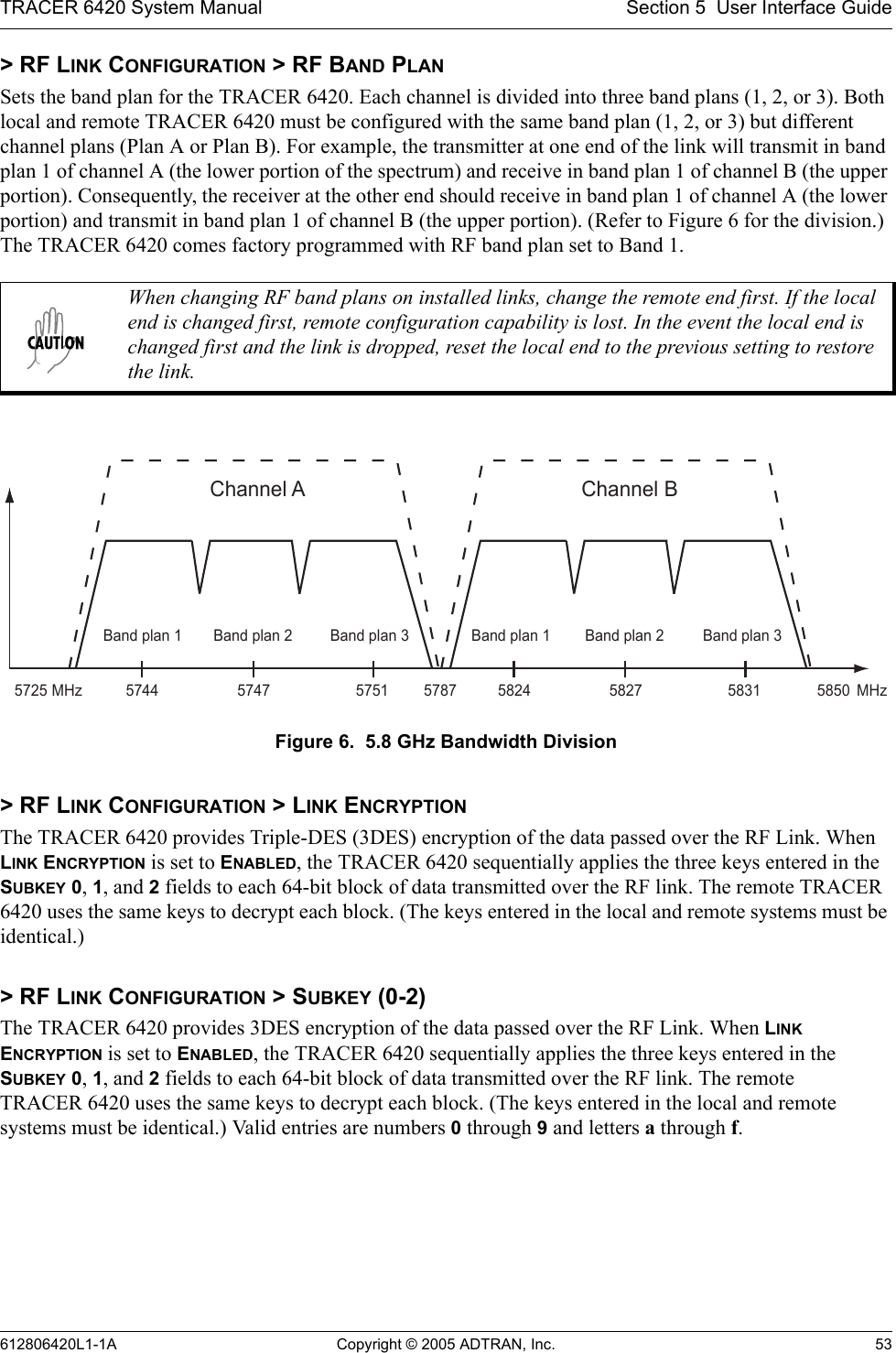
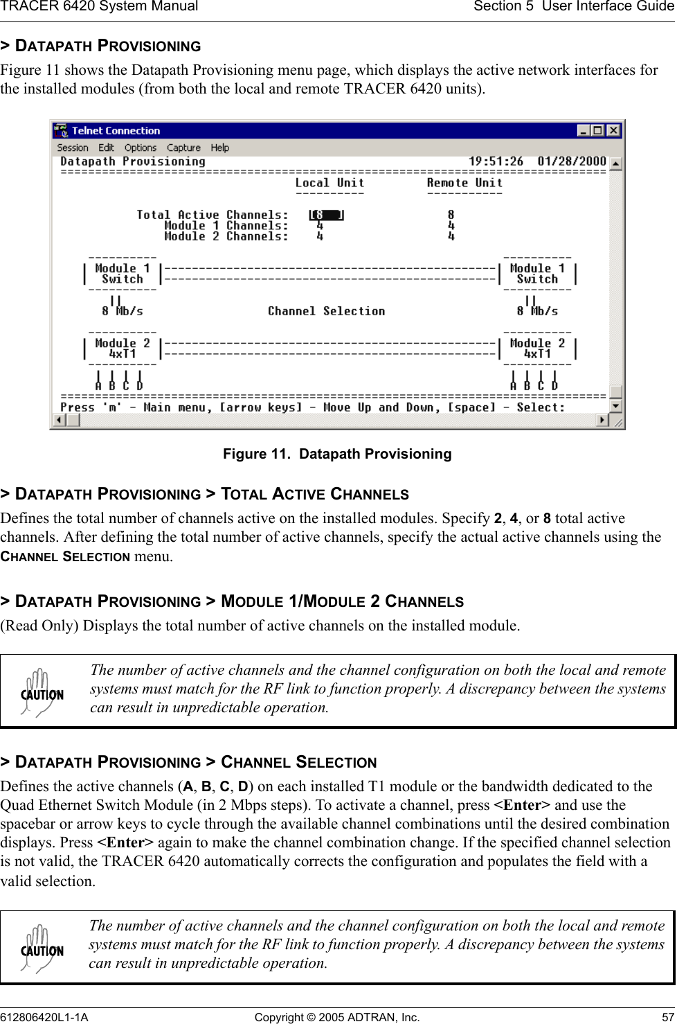
>
ADTRAN
>
TRC6420 User Manual
Users Manual Revised
Navigation menu
Upload a User Manual
Namespaces
Wiki Guide
HTML
PDF
Info
Views
User Manual
Discussion / Help
Navigation

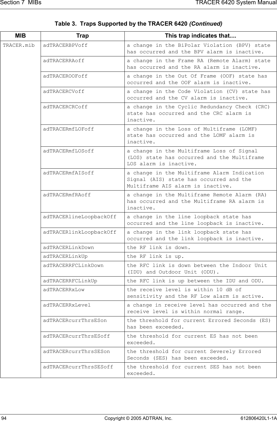
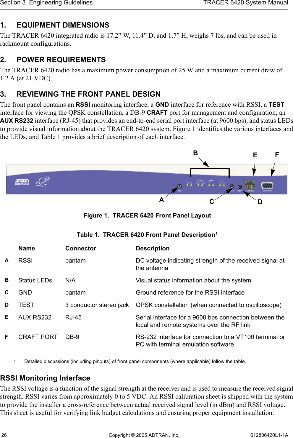
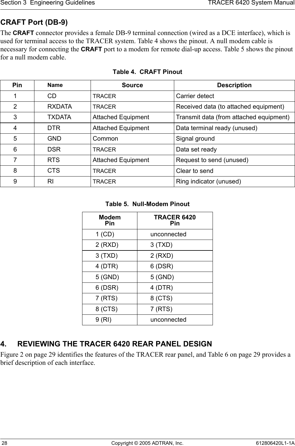
![TRACER 6420 System Manual Section 2 Microwave Path Engineering Basics612806420L1-1A Copyright © 2005 ADTRAN, Inc. 237. OTHER CONSIDERATIONSPath AvailabilityThe path availability of a wireless link is a metric that expresses the fractional amount of time a link is available over some fixed amount of time, and depends on several factors. Path availability is expressed aswhere the parameters areaterrain factor bclimate factor fcarrier frequency (GHz) dpath length (miles) Ffade margin (dB)Terrain Factor (a)The terrain factor is a quantity that compensates the link availability for different types of terrain. Generally speaking, the smoother an area's terrain is, the less availability a wireless link running over that terrain will have, primarily due to multipath reflections. In contrast, secondary microwave signals will be randomly dispersed over rough terrain and will not interfere with the main signal lobe as badly as in the smooth terrain case. The terrain factor values normally used are listed below:Climate Factor (b)The climate factor is a quantity that compensates the link availability for different types of climates (weather). In general, microwave links operating in areas with high humidity will have less availability than those in arid areas, primarily because water is a dispersive mechanism to microwave energy and causes the main signal lobe to refract and disperse away from the receiver location. The climate factor values normally used are listed below:Terrain Terrain Factor DescriptionSmooth 4water, flat desertAverage 1moderate roughnessMountainous 1/4 very rough, mountainousClimate Climate Factor DescriptionVery Dry 1/8 desert regionsTemperate 1/4 mainland, interior regionHumid 1/2 humid and coastal regionsA12.5106–×()abfd310 F10⁄–()–[]100%×=(%)](https://usermanual.wiki/ADTRAN/TRC6420/User-Guide-527946-Page-23.png)
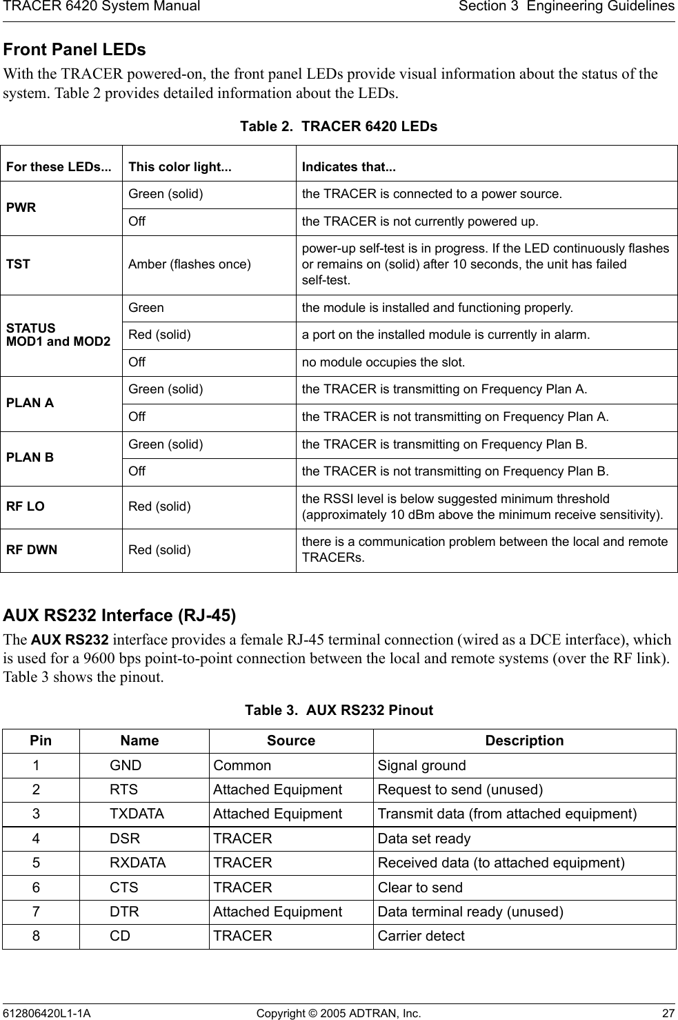
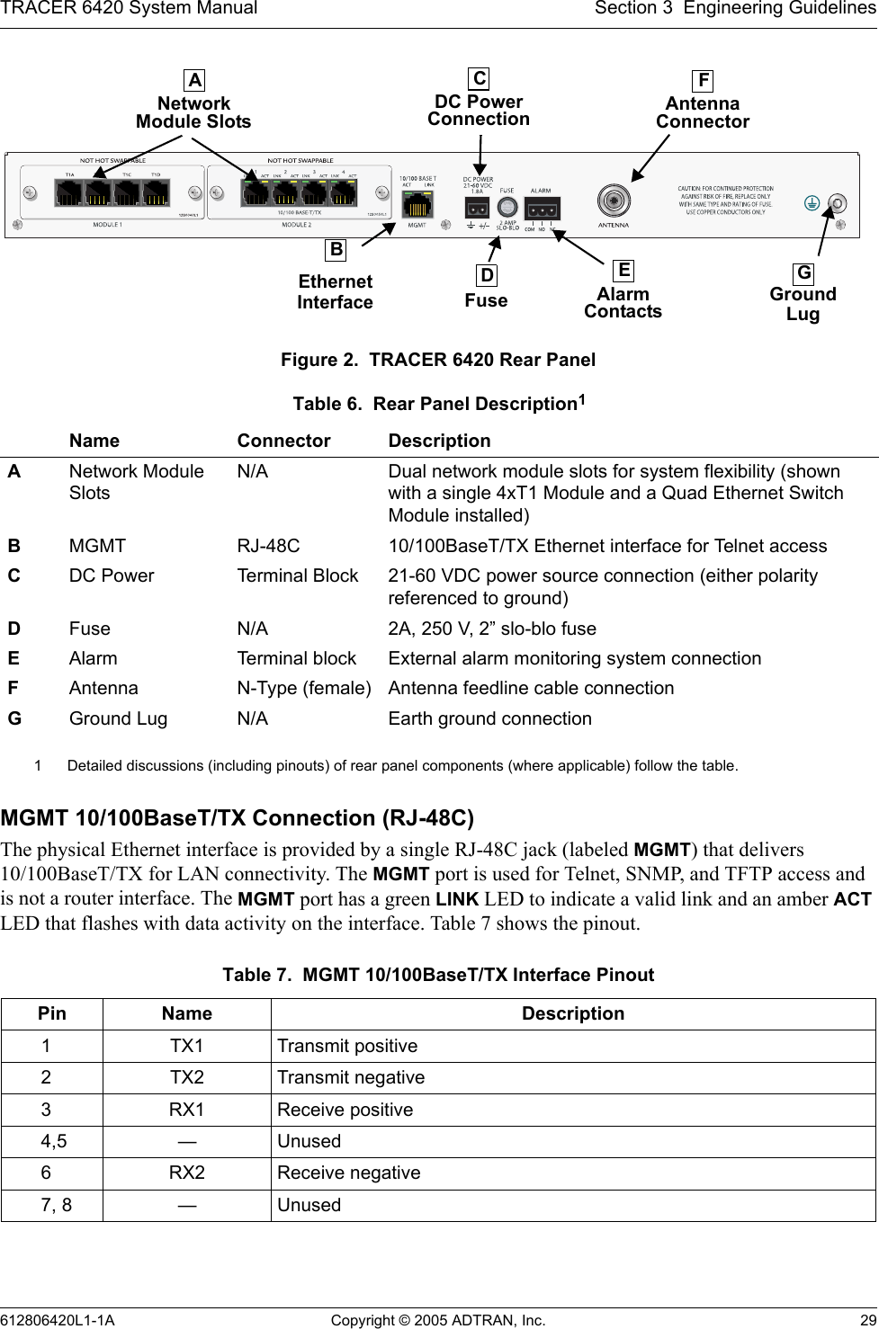

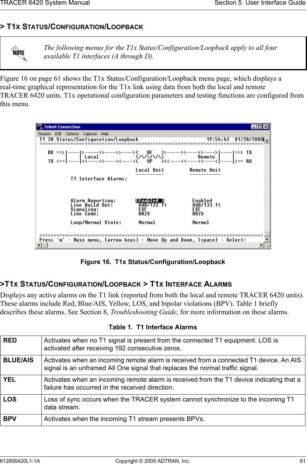
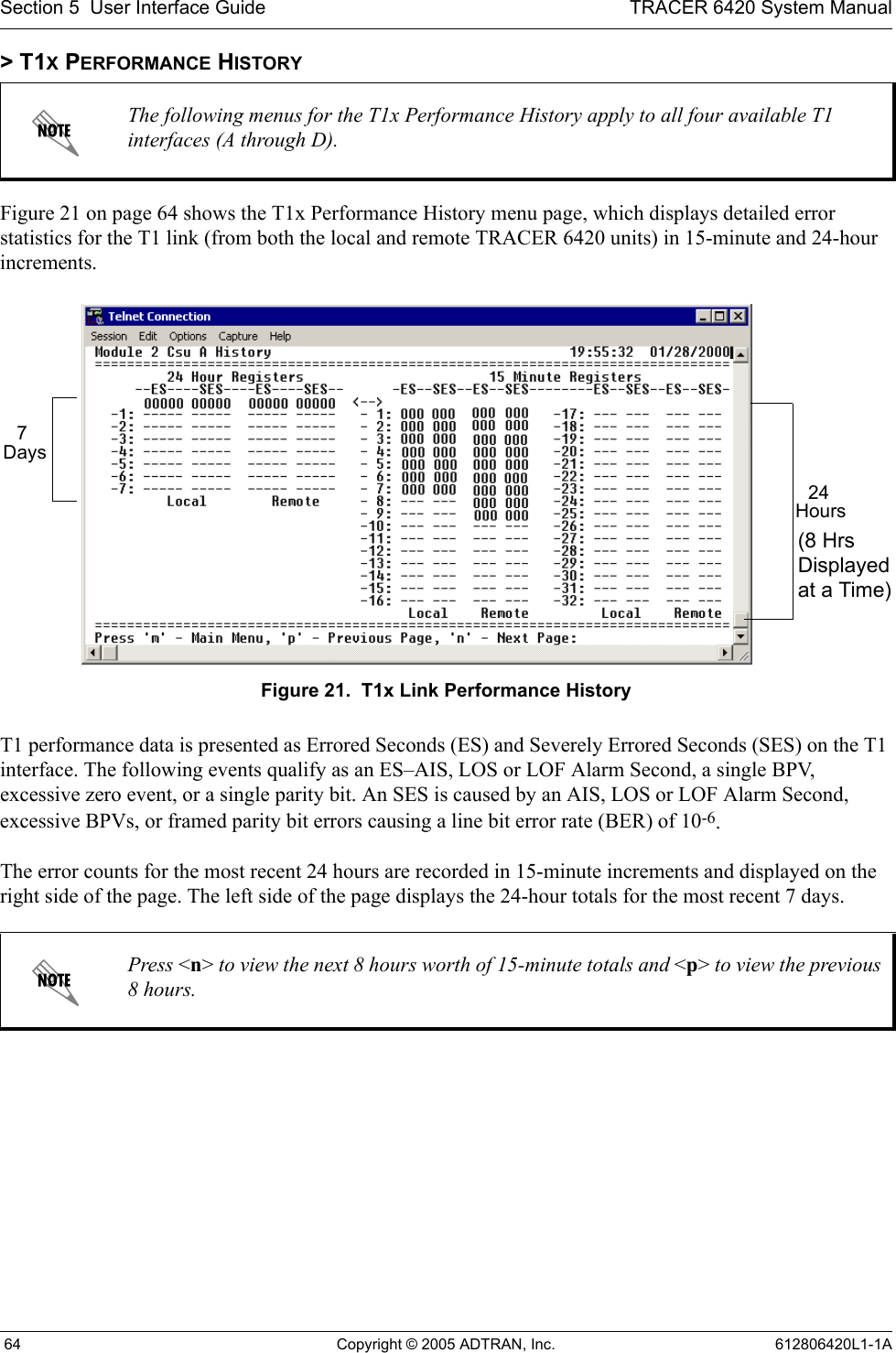
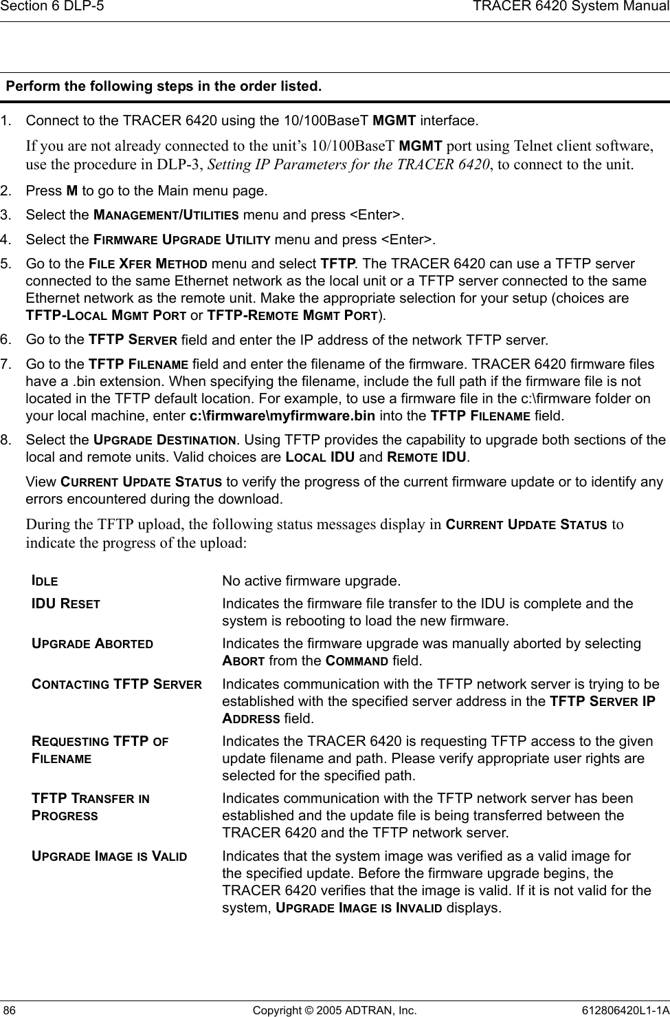
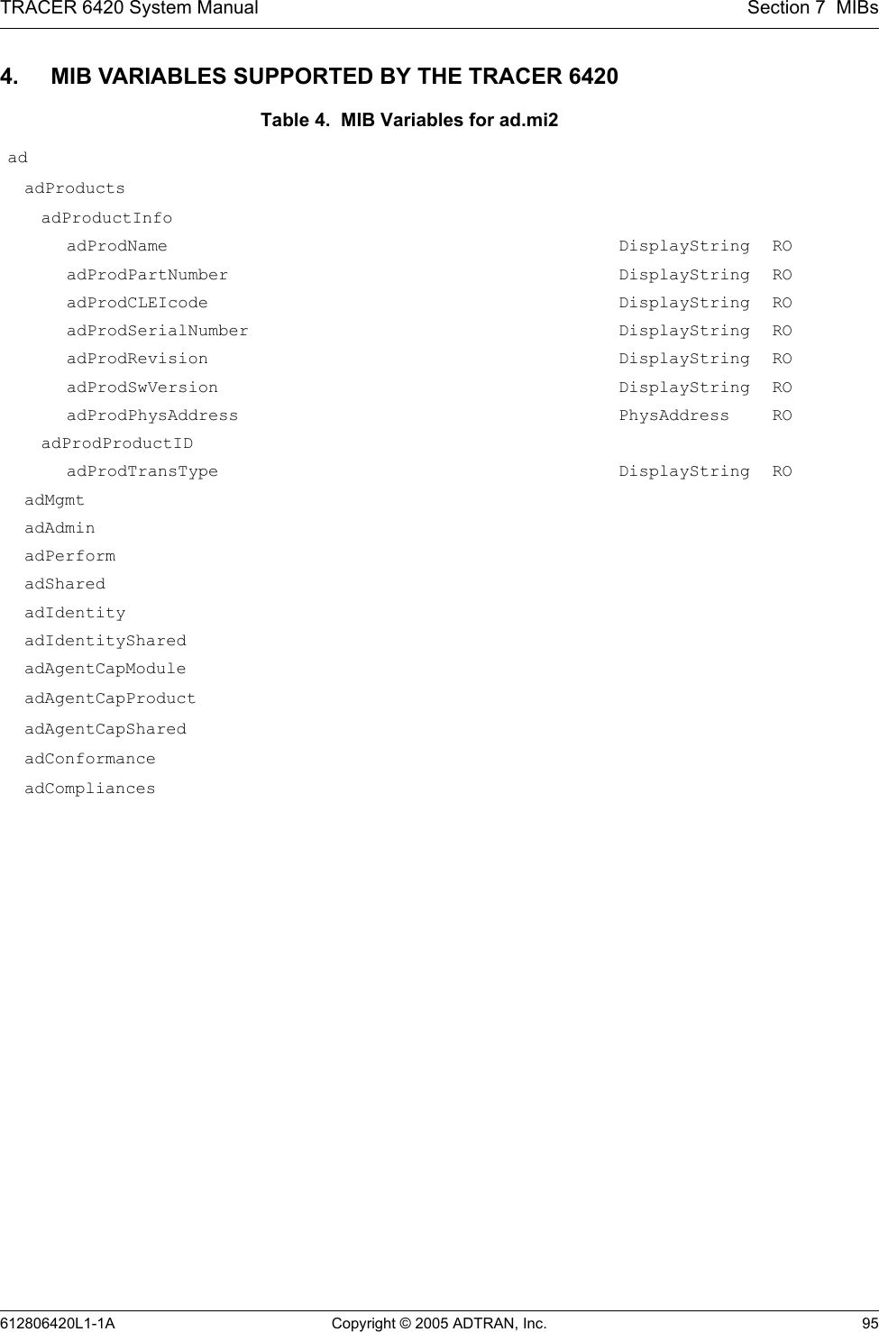
![Section 5 User Interface Guide TRACER 6420 System Manual 62 Copyright © 2005 ADTRAN, Inc. 612806420L1-1A> T1X STATUS/CONFIGURATION/LOOPBACK > ALARM REPORTINGDetermines whether the TRACER 6420 unit will report active alarms. If set to DISABLED, no alarms will be displayed on this menu page. The ALARM REPORTING parameter is independently configured for the local and remote TRACER 6420 units. When set to DISABLED, the TRACER 6420 does not report active alarms via SNMP or the CRAFT port and the status LEDs are off. By default, alarm reporting is set to ENABLED.>T1X STATUS/CONFIGURATION/LOOPBACK > T1X LINE BUILD OUTConfigures the T1 for the appropriate line buildout, based on the distance to the T1 equipment. By default, the line buildout for the TRACER 6420 is 0 dB/133 FT.> T1X STATUS/CONFIGURATION/LOOPBACK > SIGNALINGConfigures the framing format for the T1 link for both the local and remote TRACER 6420 units. The TRACER 6420 transports T1 data across the link (as long as the T1 signal is properly timed). Configure the framing format (using the SIGNALING menu) to enable the TRACER 6420 to monitor incoming framing error events and indicate problems with the attached metallic service. The TRACER 6420 supports both extended superframe (ESF) and superframe (D4) framing formats. By default, the signaling method is set to ESF.> T1X STATUS/CONFIGURATION/LOOPBACK > LINE CODESets the line coding for the T1 link. The TRACER 6420 supports bipolar eight-zero substitution (B8ZS) and alternate mark inversion (AMI) line coding. By default, the line code is set to B8ZS.> T1X STATUS/CONFIGURATION/LOOPBACK > LOOP/NORMAL STATEControls the loop status of the T1 link. Activates/deactivates loopback conditions for testing purposes.> T1X STATUS/CONFIGURATION/LOOPBACK > LOOP/NORMAL STATE > NORMALDefines the T1 link as normal data transport mode; there are no active loopbacks.> T1X STATUS/CONFIGURATION/LOOPBACK > LOOP/NORMAL STATE > LINK [LOCAL]Activates a loopback at the local TRACER 6420 T1 framer towards the remote end of the wireless link (see Figure 17). Use the local LINK loopback to loop the data transmitted from the remote end of the link back across the radio link to the remote end of the link. This loopback tests the integrity of the radio link and all the associated digital and RF hardware.Figure 17. T1 Local Link Loopback](https://usermanual.wiki/ADTRAN/TRC6420/User-Guide-527946-Page-62.png)
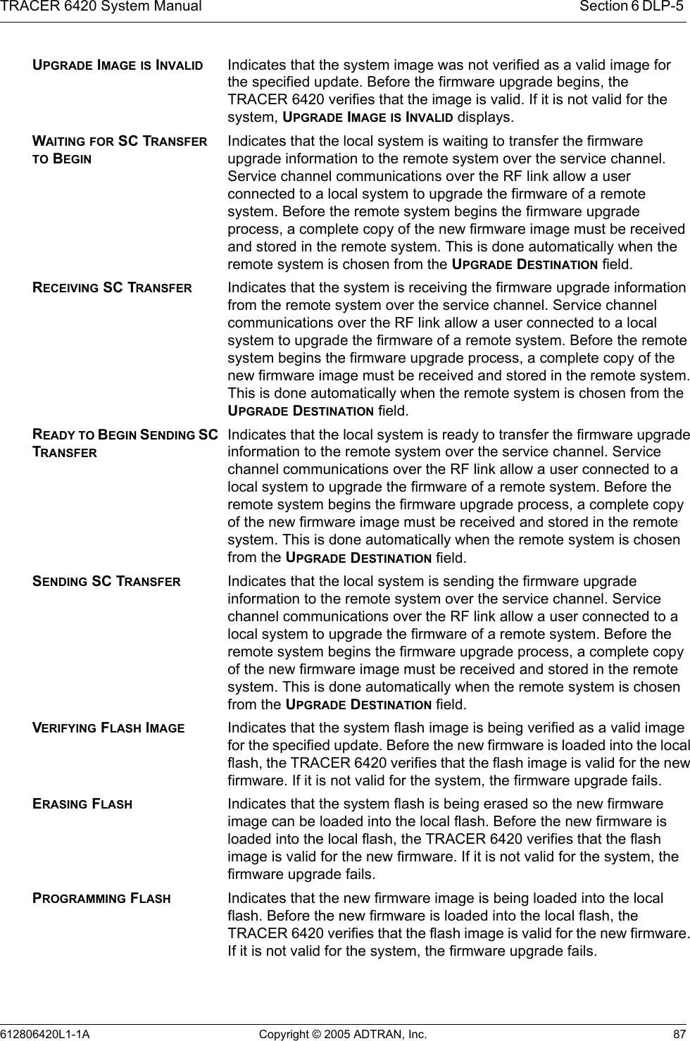
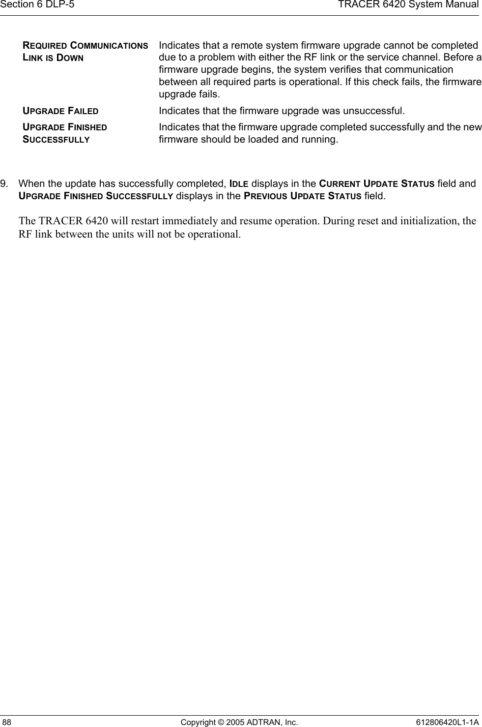
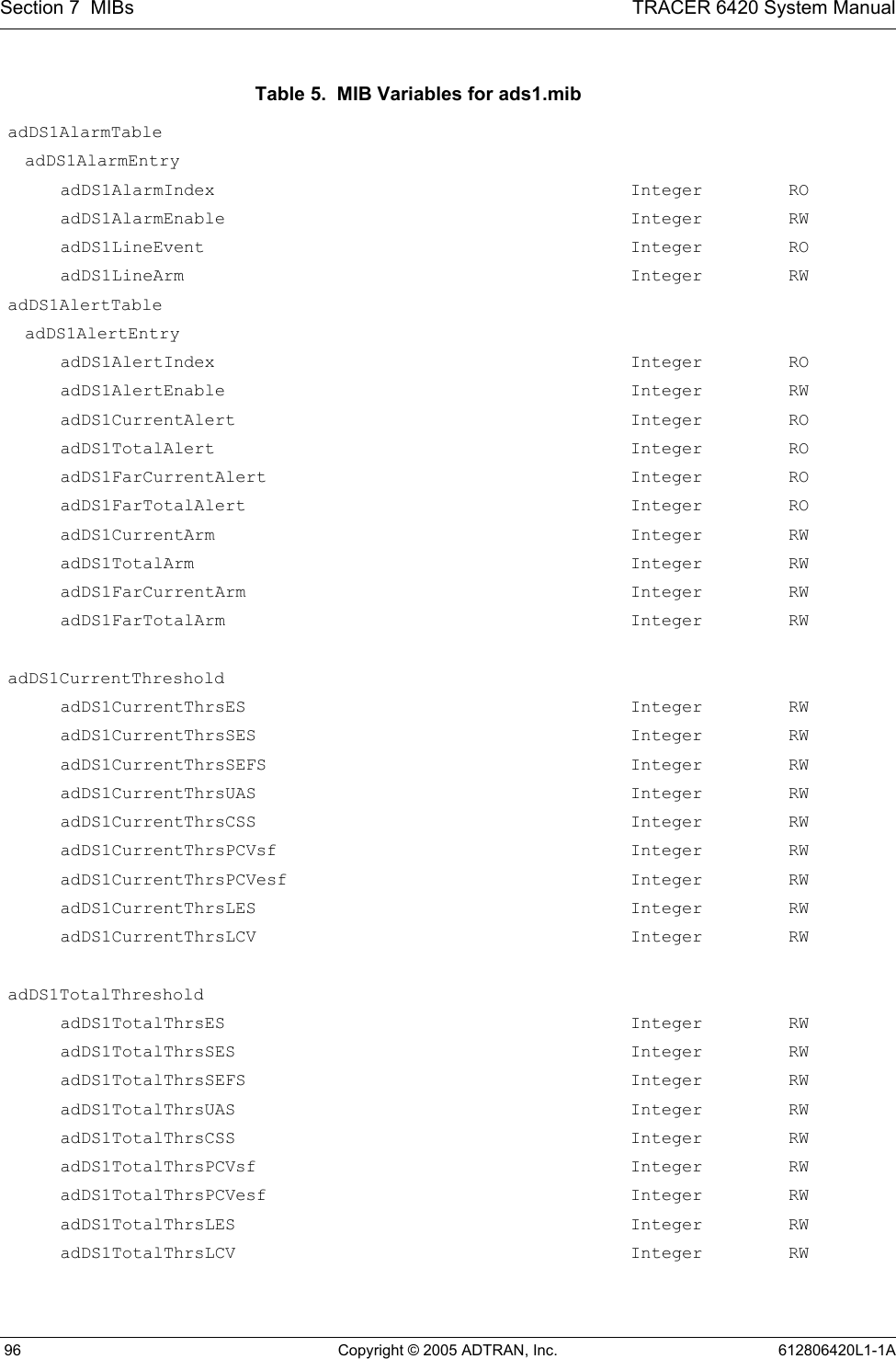
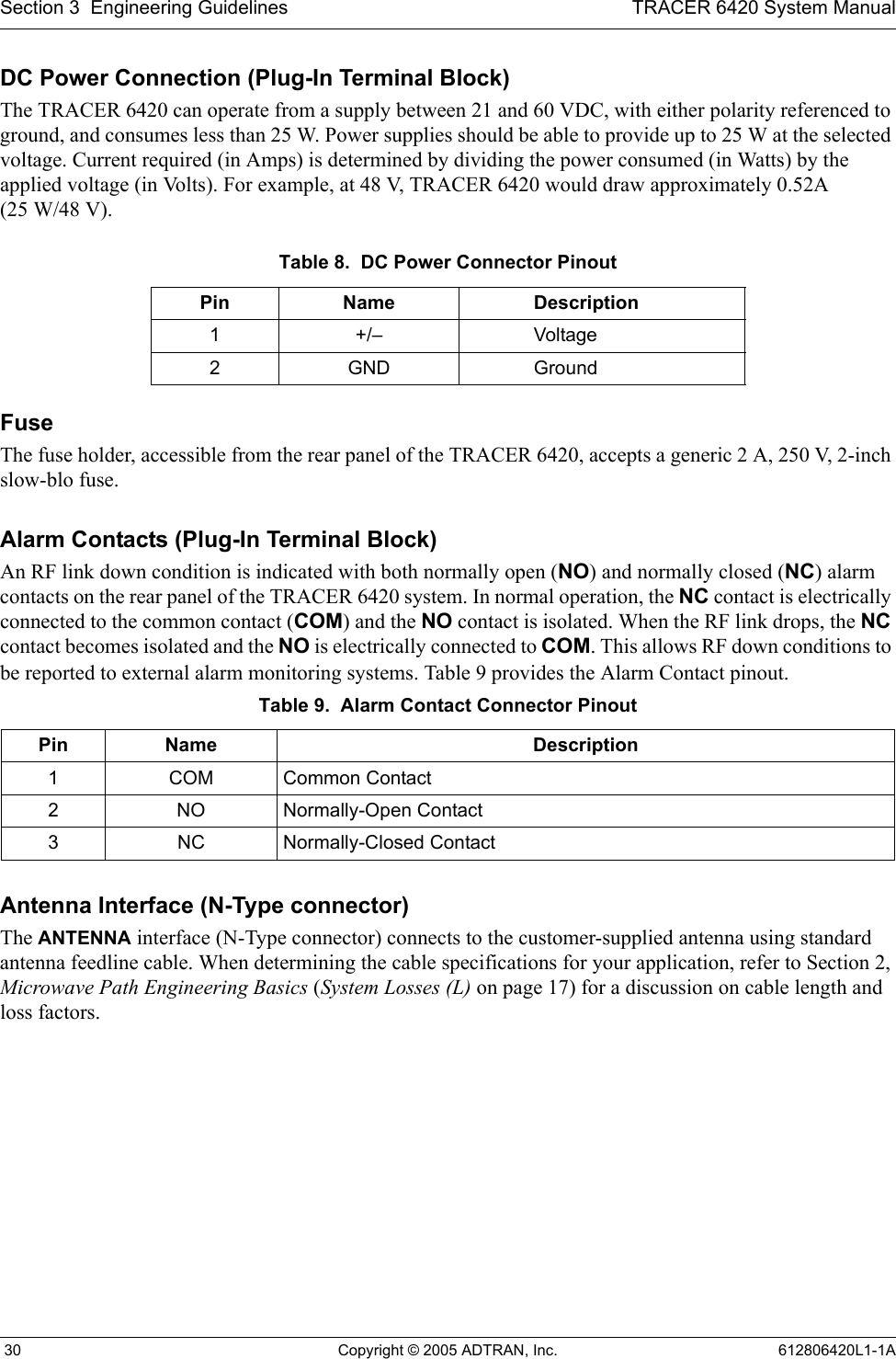
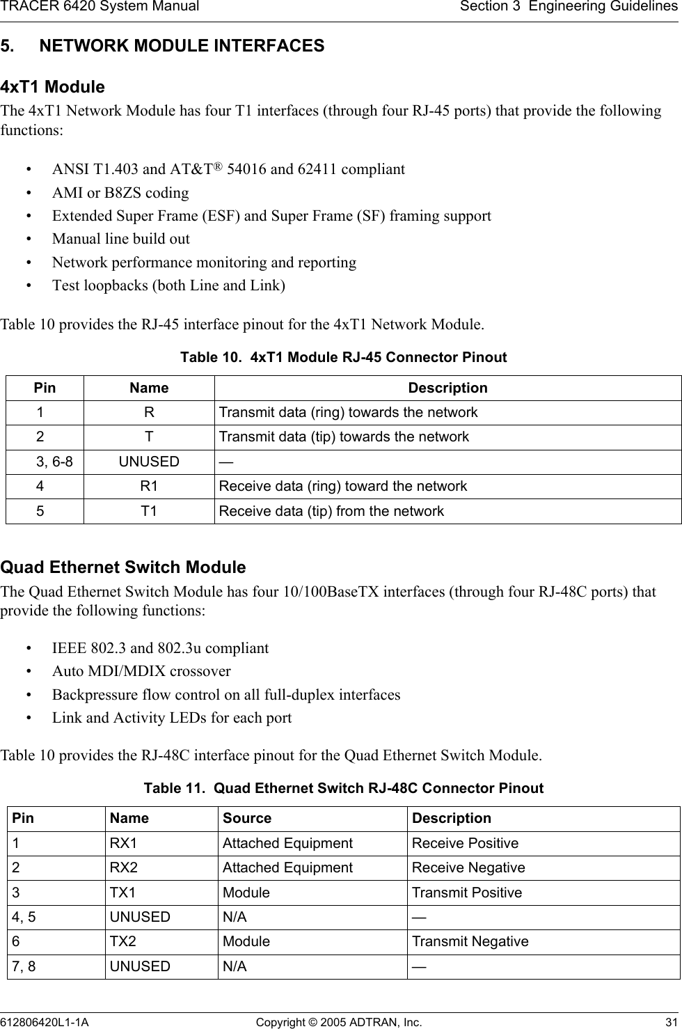
![TRACER 6420 System Manual Section 5 User Interface Guide612806420L1-1A Copyright © 2005 ADTRAN, Inc. 63> T1X STATUS/CONFIGURATION/LOOPBACK > LOOP/NORMAL STATE > LINK [REMOTE]Activates a loopback at the remote TRACER 6420 T1 framer towards the local end of the wireless link (see Figure 18). Use the remote LINK loopback to loop the data transmitted from the local end of the link across the radio link to the local end of the link. This loopback tests the integrity of the radio link and all the associated digital and RF hardware.Figure 18. T1 Remote Link Loopback> T1X STATUS/CONFIGURATION/LOOPBACK > LOOP/NORMAL STATE > LINE [LOCAL]Activates a loopback at the local TRACER 6420 T1 framer towards the connected T1 equipment (see Figure 19). Use the local LINE loopback to test data path integrity from the local TRACER 6420 unit to the connected T1 equipment.Figure 19. T1 Local Line Loopback> T1X STATUS/CONFIGURATION/LOOPBACK > LOOP/NORMAL STATE > LINE [REMOTE]Activates a loopback at the remote TRACER 6420 T1 framer towards the connected T1 equipment at the remote end of the link (see Figure 20). Use the remote LINE loopback to test data path integrity from the remote TRACER 6420 unit to the T1 equipment connected at the remote end of the link.Figure 20. T1 Remote Line Loopback](https://usermanual.wiki/ADTRAN/TRC6420/User-Guide-527946-Page-63.png)